Project 1 : CFD Meshing for Tesla Cyber Truck
AIM: To Check all the Geomentrical errors and assign PIDs and To perform CFD Meshing for Tesla Cyber Truck .
SOFTWARE USED : ANSA Software.
TOOLS USED IN SOFTWARE : Checks, Topo Deck, Loop, Fill Hole, Spacing, Parameters Tool for length, Mesh Generation Tool for meashing, Volumetric mesh.
PROCEDURE :
1. Downloaded the model from the challenge and saved it in a specified location.
2. Inserting the downloaded model in to ANSA Software.
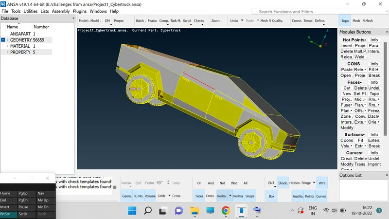
3. Learning the given question and understanding it.
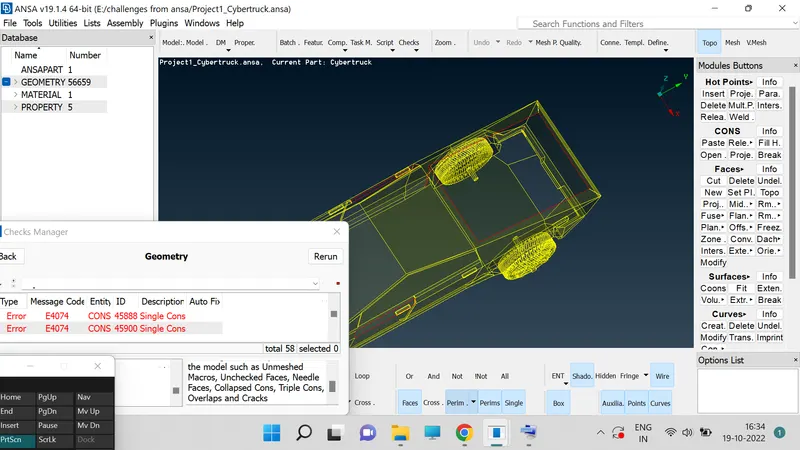
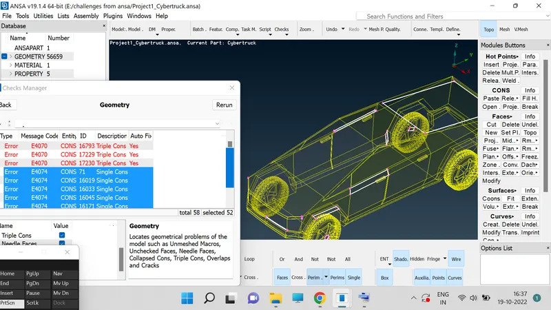
4. Go to checks option to check the "Geomentry", Errors in the model.
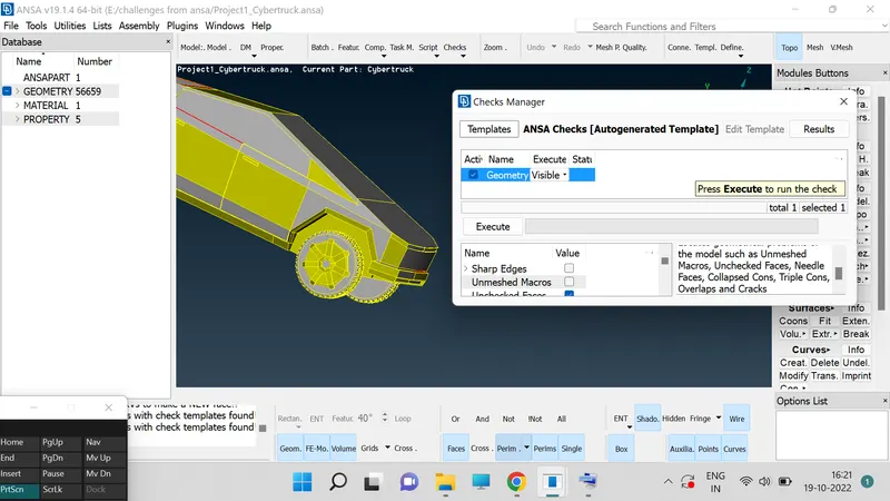
5. In the checks we have an option "Geomentry", click on it and then we will get option like (i.e : sharp edgs, unmeshed macros, uncracked surfaces, colapsed cones, triple cones, nedial faces, over laped faces, cracks, single cones.) out of which select all the required items to get your required output.
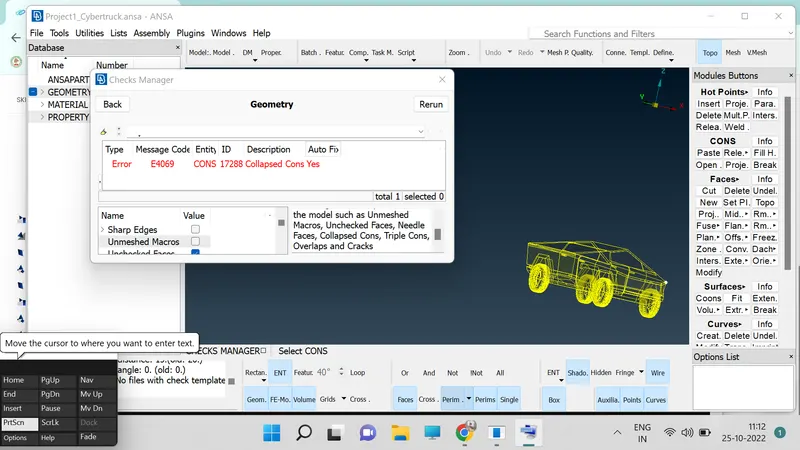
6. After doing checks we will get the clear information of "cracks" and "single cones" and "triple cones" on our model and we need to resolve each and every error using the different tools in ANSA.
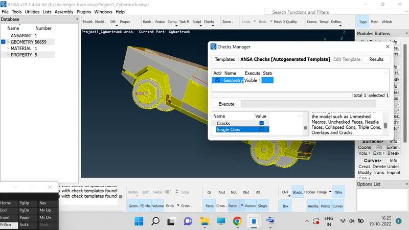
7. After clicking on the "Execute", option we will be getting the clear details of errors.
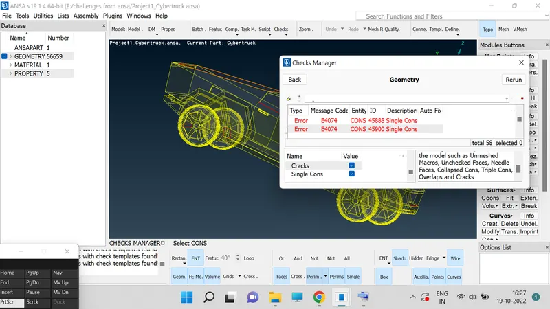
8. In our model single cones are represented my the red lines.
9. Go to "Topo deck", for future operation.
10. In Topo deck we have an tool called "Faces", in which we have "New", click in it then a window will be popup over their in which we have four option like (i.e : existing surface, planner, cones, fitter.) by using those we can clearly complete the filling operation of missing surface in model.
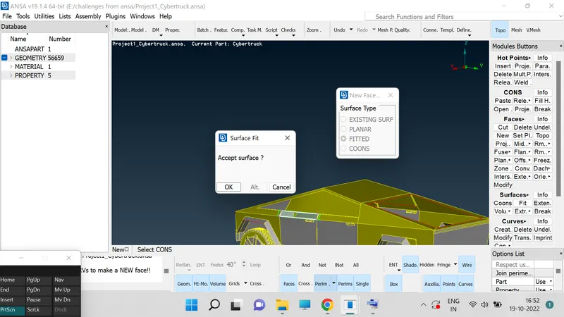
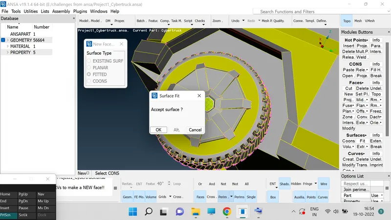
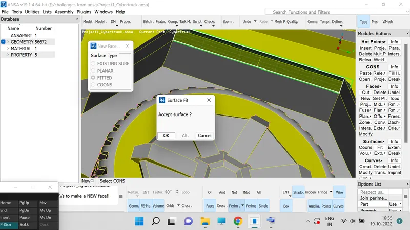
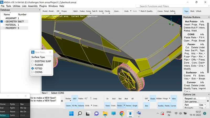
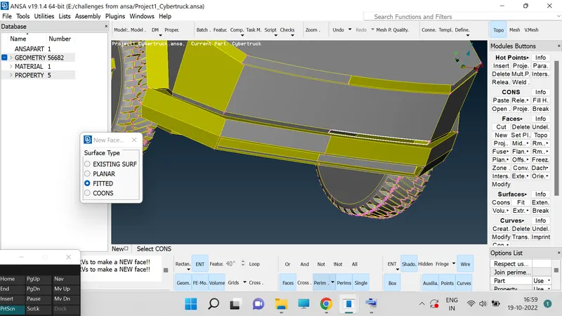
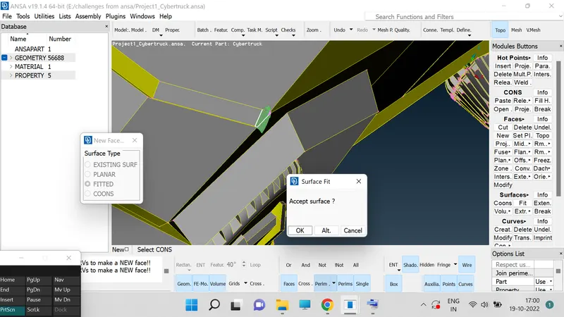
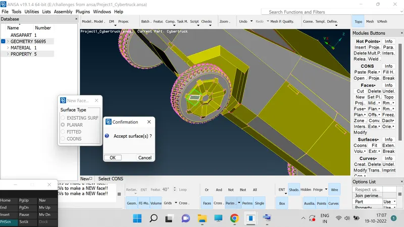
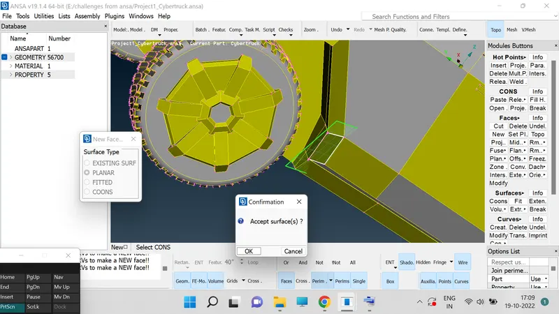
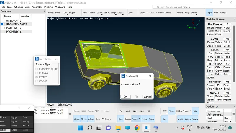
11. In cones we have a option called fill hole use it to fill the holes in the model.
12. Use control and shift key to see the wire frame mode of ur model to select the hidden surfaces during the operation.
13. Go to "Geomentry" "checks", click on exucute option.
14. Now assign the PIDs.
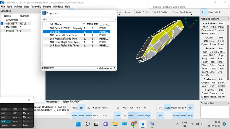
15. Go to "Properties", and click on it then a box will be popup in which we need to select one by one and assign required PIDs.
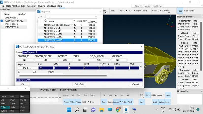
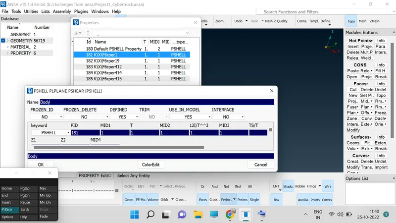
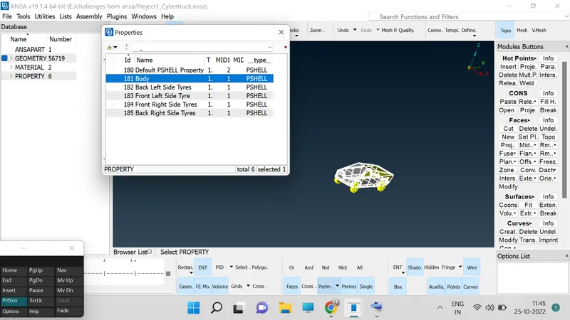
16. By double clicking on the color nodes we can select the color of the PIDs.
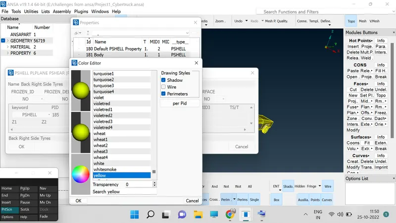
17. Click on the one part then new box will be popup in which click on apply then select the body to assign the PID.
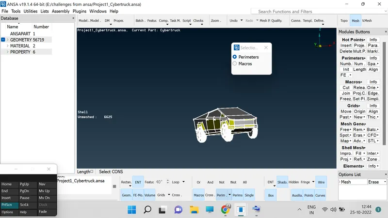
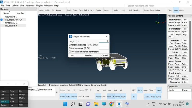
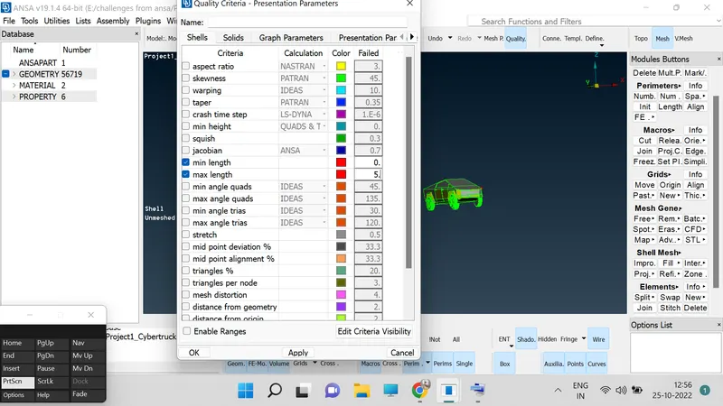
18. Go to parameters Tool click on it then a window will be popup in which two sets will be visible one is "PARAMETER", and secound is "MACROS".
19. Go to "PARAMETER", and click on middle botton then a window will be popup then set the dimensions as 1 and do the same for the "MACROS", and set the dimension as 1.
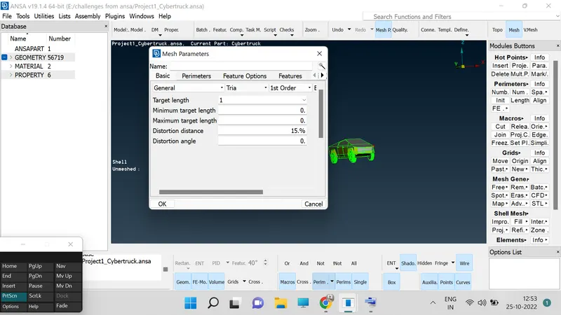
20. Go to "MESH PARAMETER", and set the target length 1 and select the "Tria", option over their.
21. Define the mesh element type us a tria in the "MESH PARAMETER".
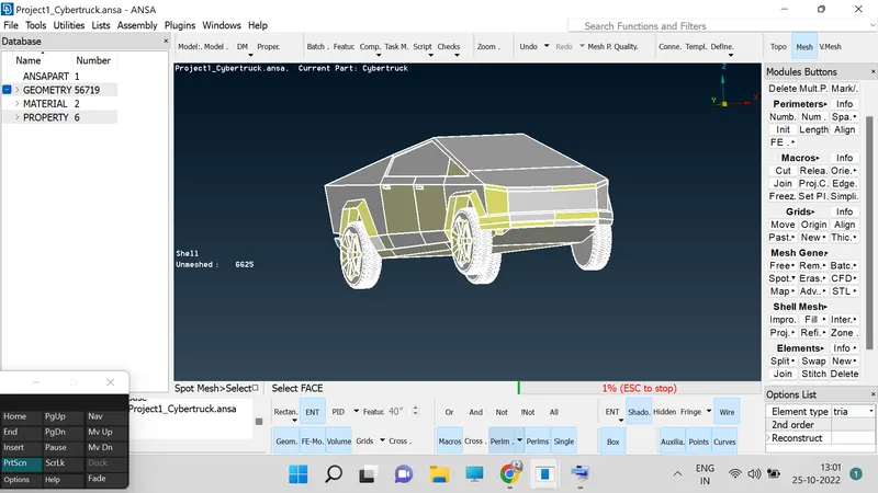
22. Go to "MESH GENERATION", tool in which we have "SPORT MESH", click on the option and then select the entire module then the module will be turned in to mesh.
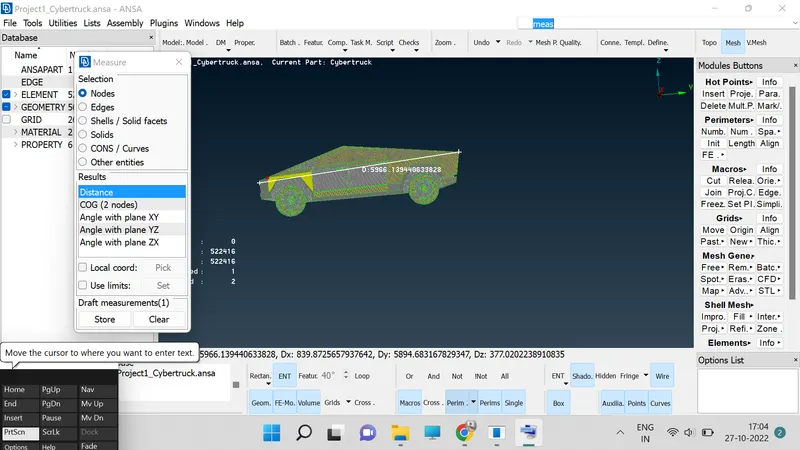
23. Now go to "MESUREMENTS", option at the top of the screen and then click on it then window will be pop up then select the nodes option.
24. After selecting the nodes option we need to measure the distance between to nodes on the model by selecting two nodes.
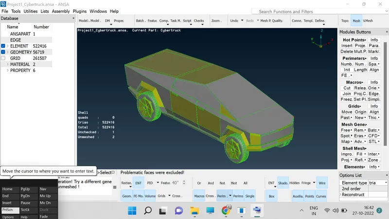
25. Below is the details of "Meshed Cybertruck".
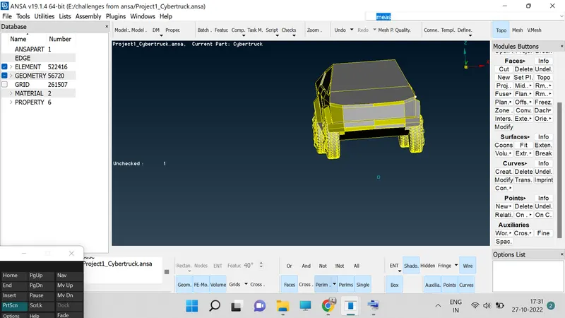
26. Now we will create the wind tonnel and lets mesh it up too.
27. Before going for meshing check the distance of your vechile by selecting the two extreme nodes point of the car.
28. Go "MESUREMENTS", option and click on the "NODES", then select the two nodes in which we need to measure distance.
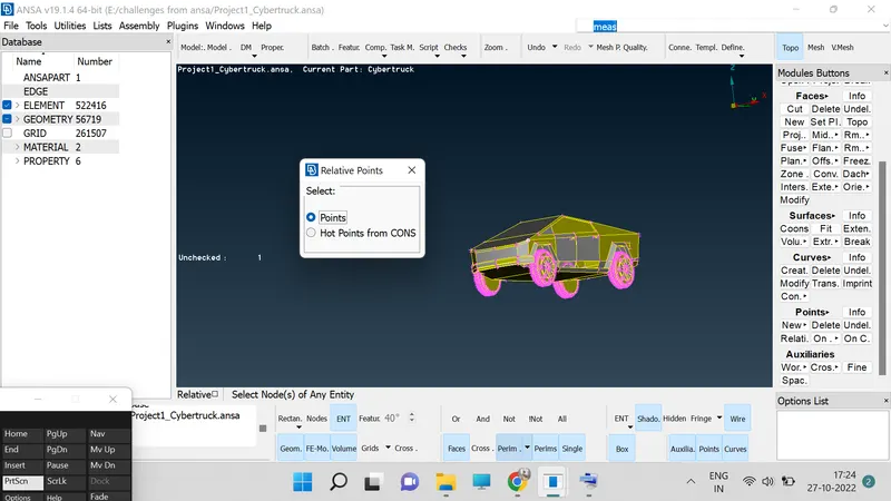
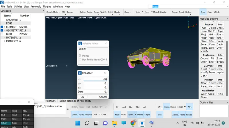
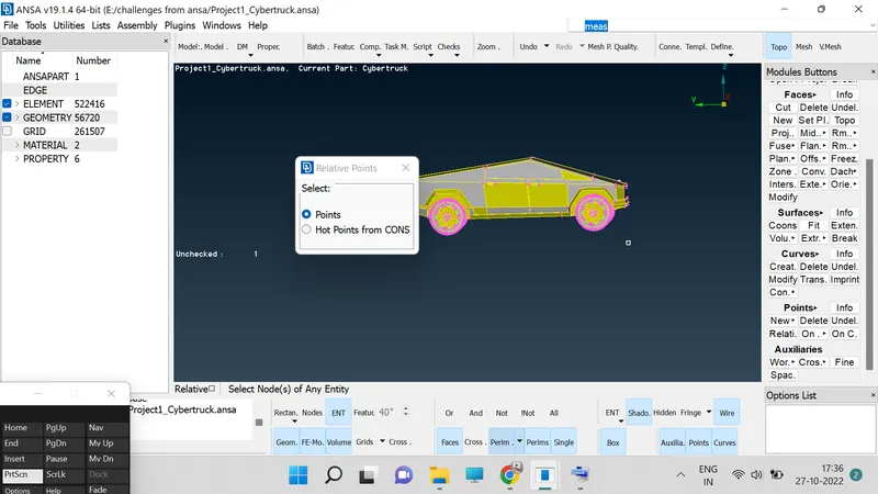
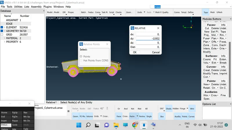
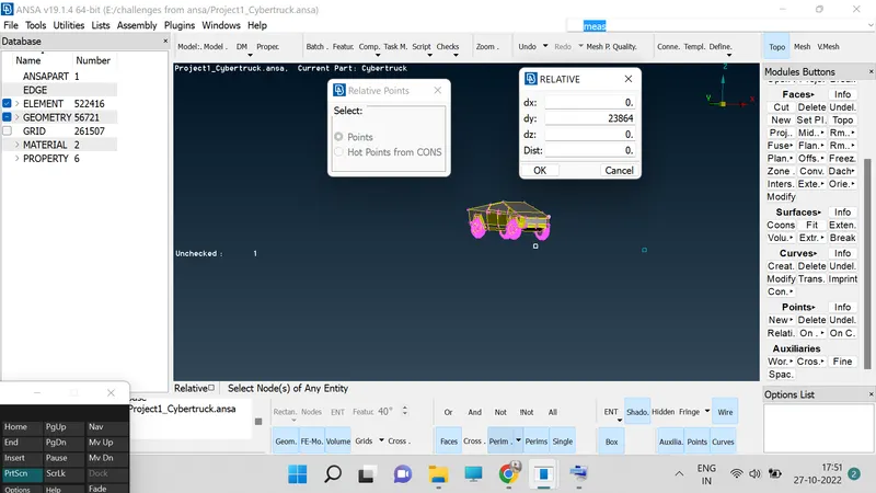
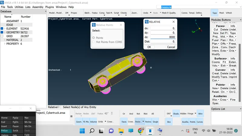
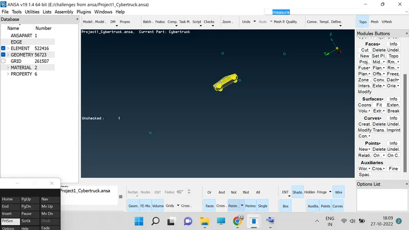
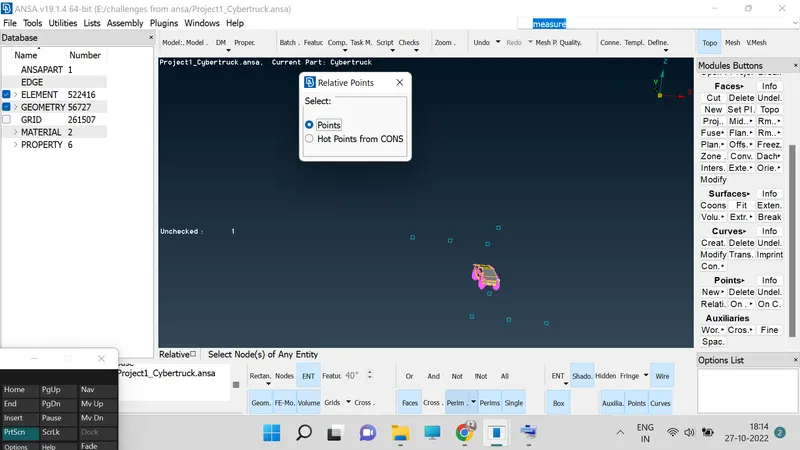
29. We need to create surface for that we need to construct a points for that go to Topo>Points>Relatives and a window will be popup in which we have points>Select a point>Select the direction on which we required the point to be project with distance.
30. Create a curve depending on the points.
31. Go to Topo>Curves>Create>Select the points and draw a curve.
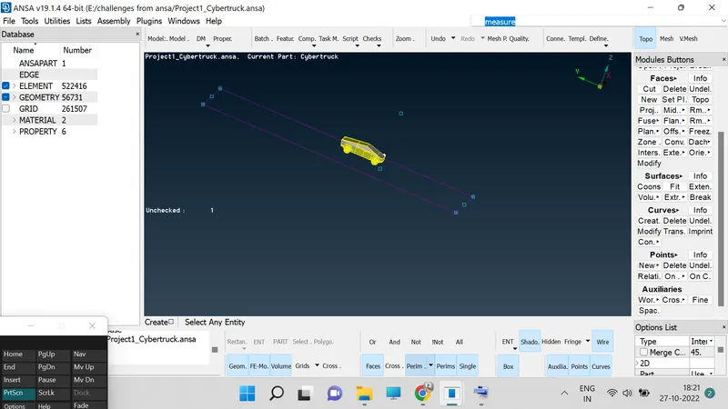
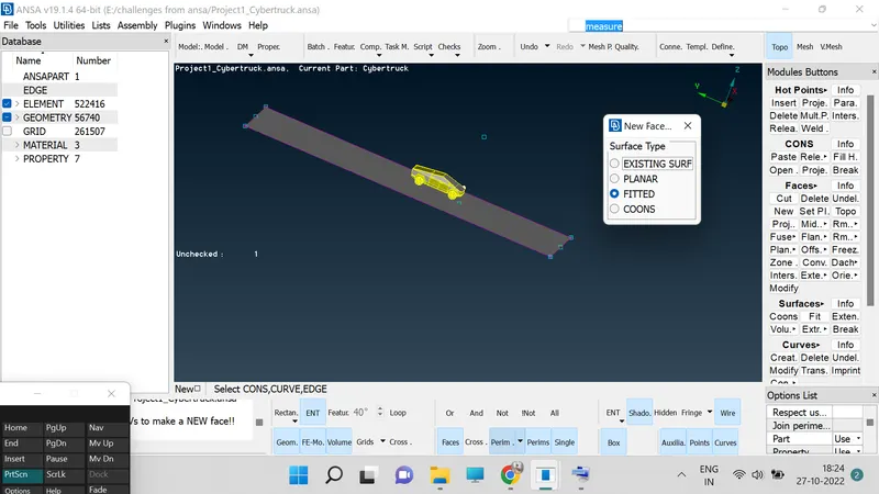
32. Create a surface depending on the points by the help of Faces>New>Fitted.
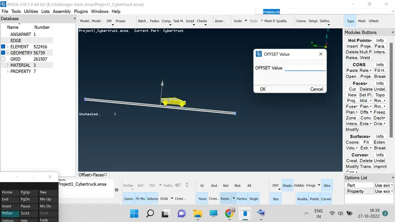
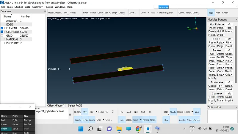
33. create the offset of the base surface by the help of Faces>Offset and select the direction to create surface.
 \
\
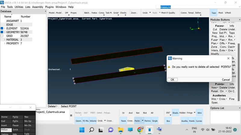
34. Now delete the "Hotpoints", which we created for reference purpose.
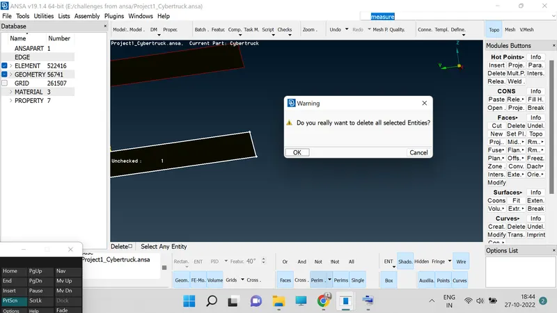
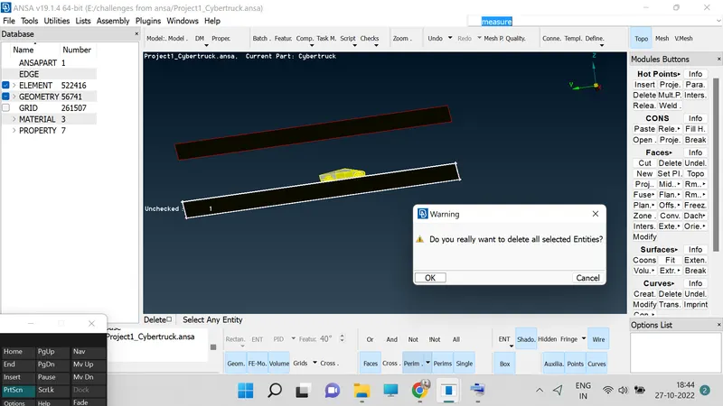
35. Now create the side walls using the base and top surfaces.
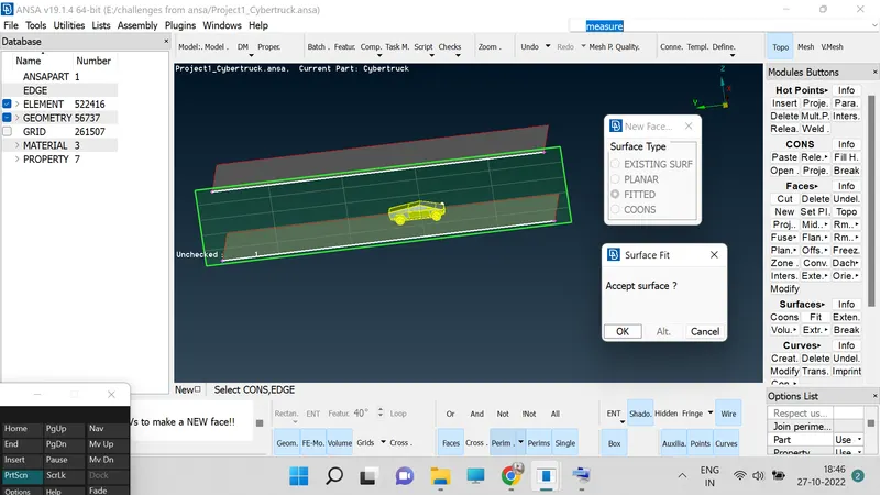
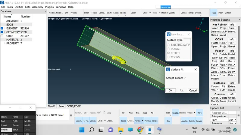
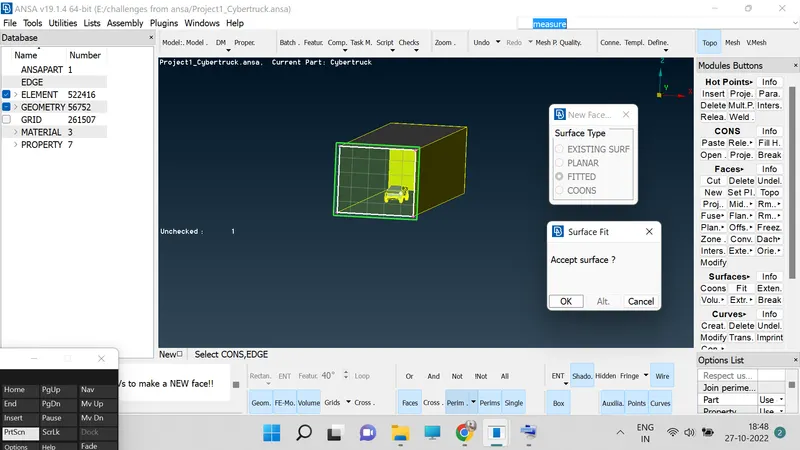
36. Assign the PIDs to the newly created surfaces.
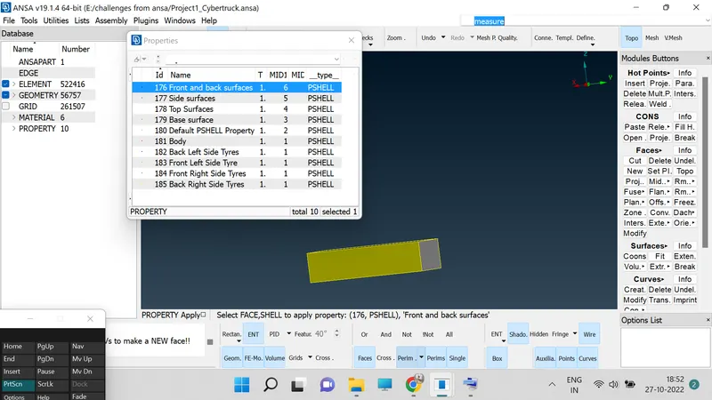
37. Now we are concentrating on meshing of surfaces.
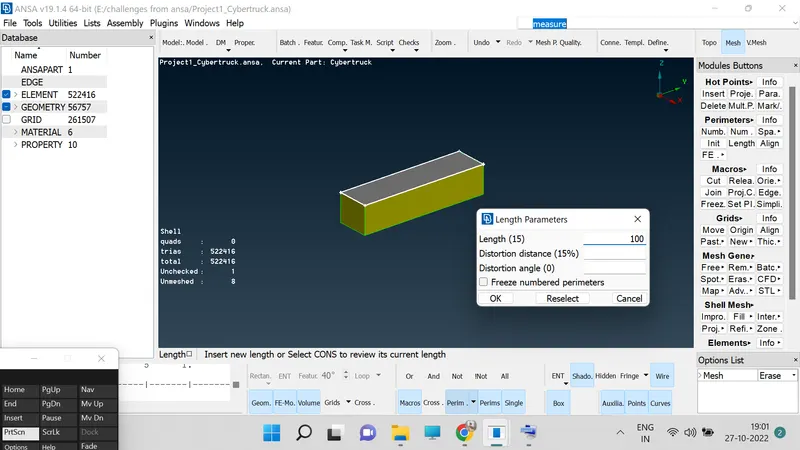
38. Now we need to get variable mesh length for bottom to top connecting surface for that we need to use Perimeter>Spacing>Basing>Change the 'Linear' to 'Geomentric'>Factor 1.1>d min = 20>d limit =100.
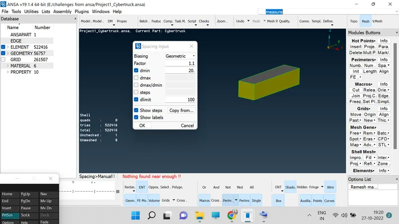
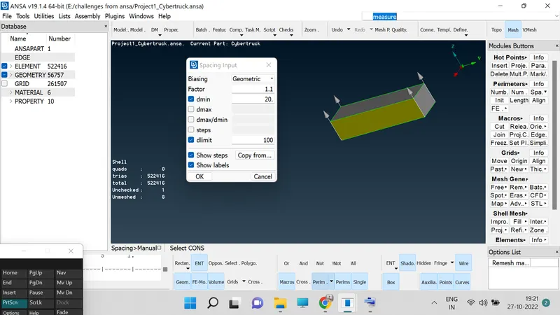
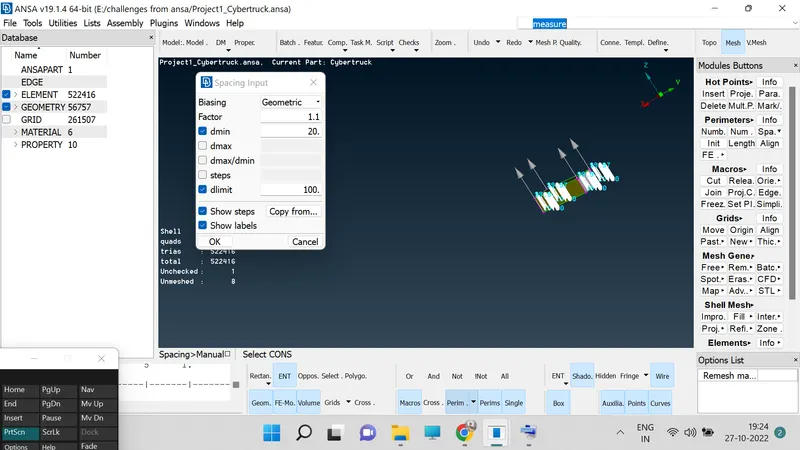
39. When we have variations in mesh length then we need not have to use the quality criteria and mesh parameter.
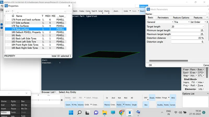
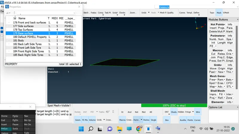
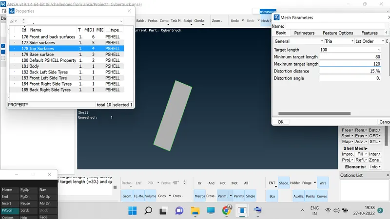
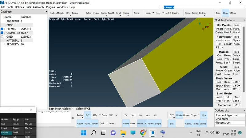
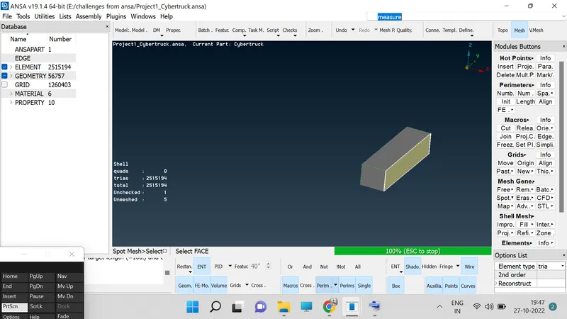
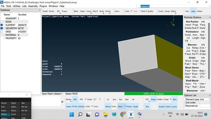
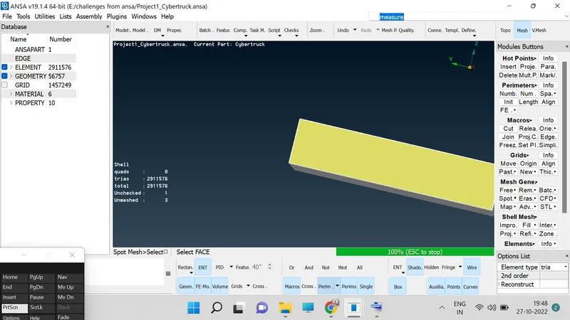
40. Go to topo mode and isolate the top and bottom surface for mesh them individually.
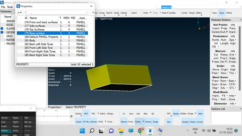
Bottom surfaces
Top surfaces
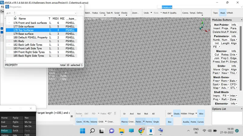
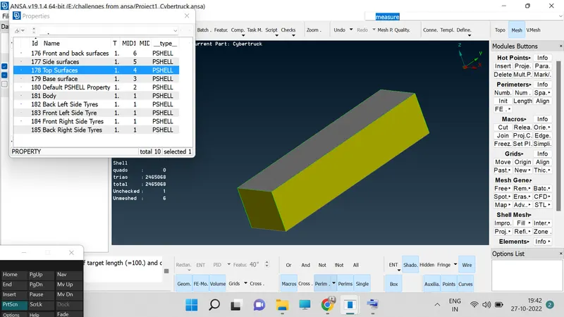
41. Select the surfaces one by one to do mesh.
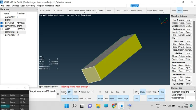
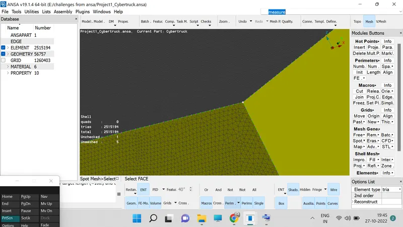
42. After completing till here we can go for Volumetric Mesh> Define> Work on hole data base> one window will get pop up.
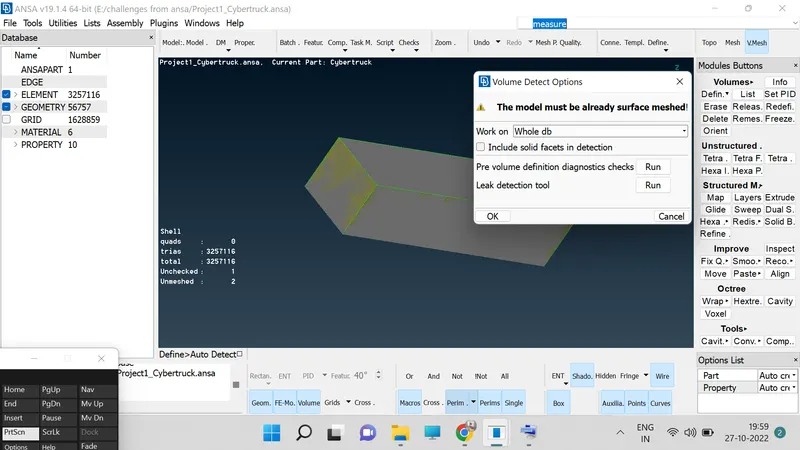
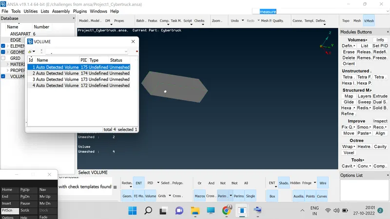
43. Now we have to select only one in which we have the outer surface with car.
44. Delete remaining points in which we are having rest of the car parts.
45. Now click on the "REMESH", to get the model in remesh format.
Results:-
Hence we have studied and implimenting of learned skills and developed the given model in to meshing and volumetric meshing using the ANSA Software.
Conclusion:-
In ANSA Software we learned how to clear the Geomentric errors, working on the Topo deck, Meshing, Spot Meshing, Volumetric Meshing.
https://drive.google.com/file/d/1AzJYUq-T_YFepj4sA3_eGVYp65FEBBjn/view?usp=sharing