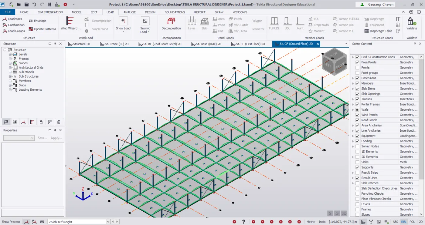
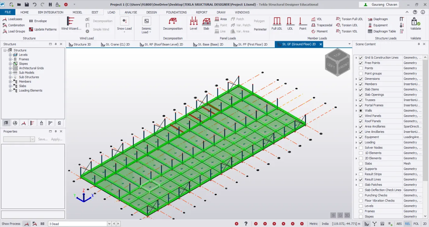
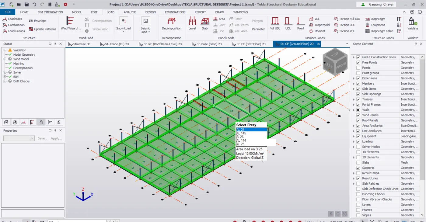
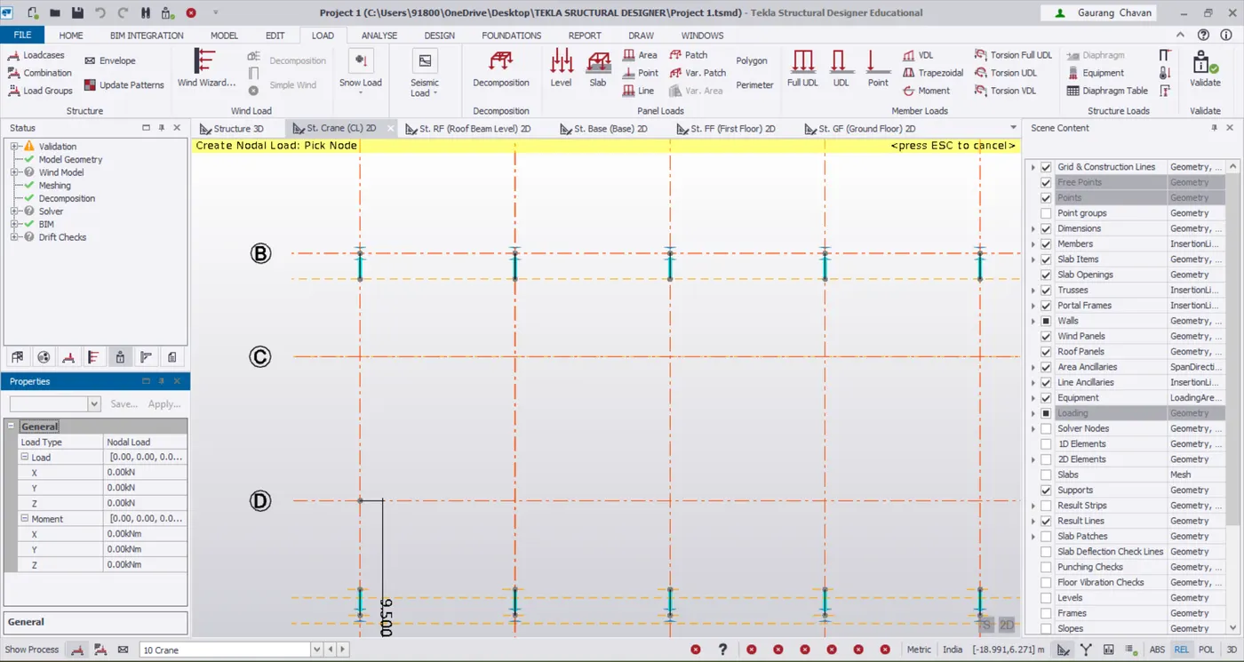
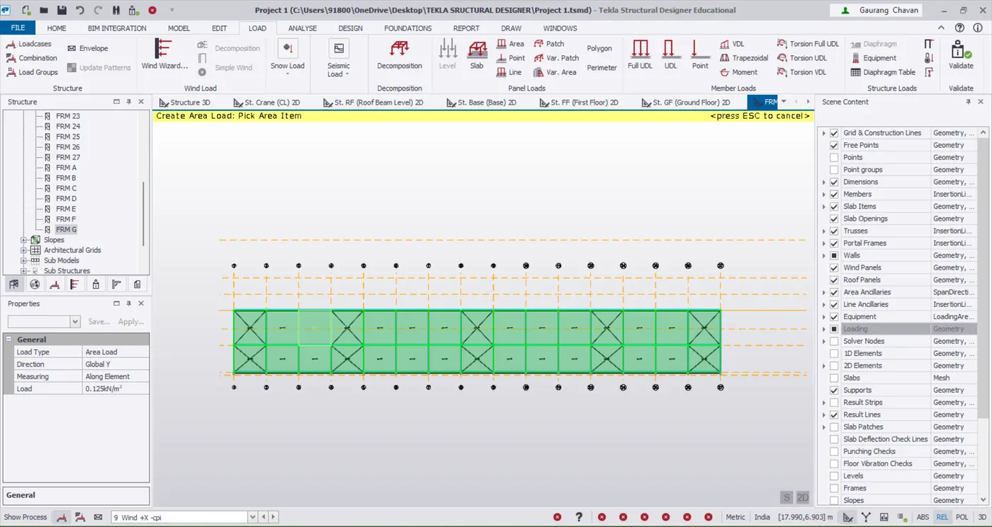
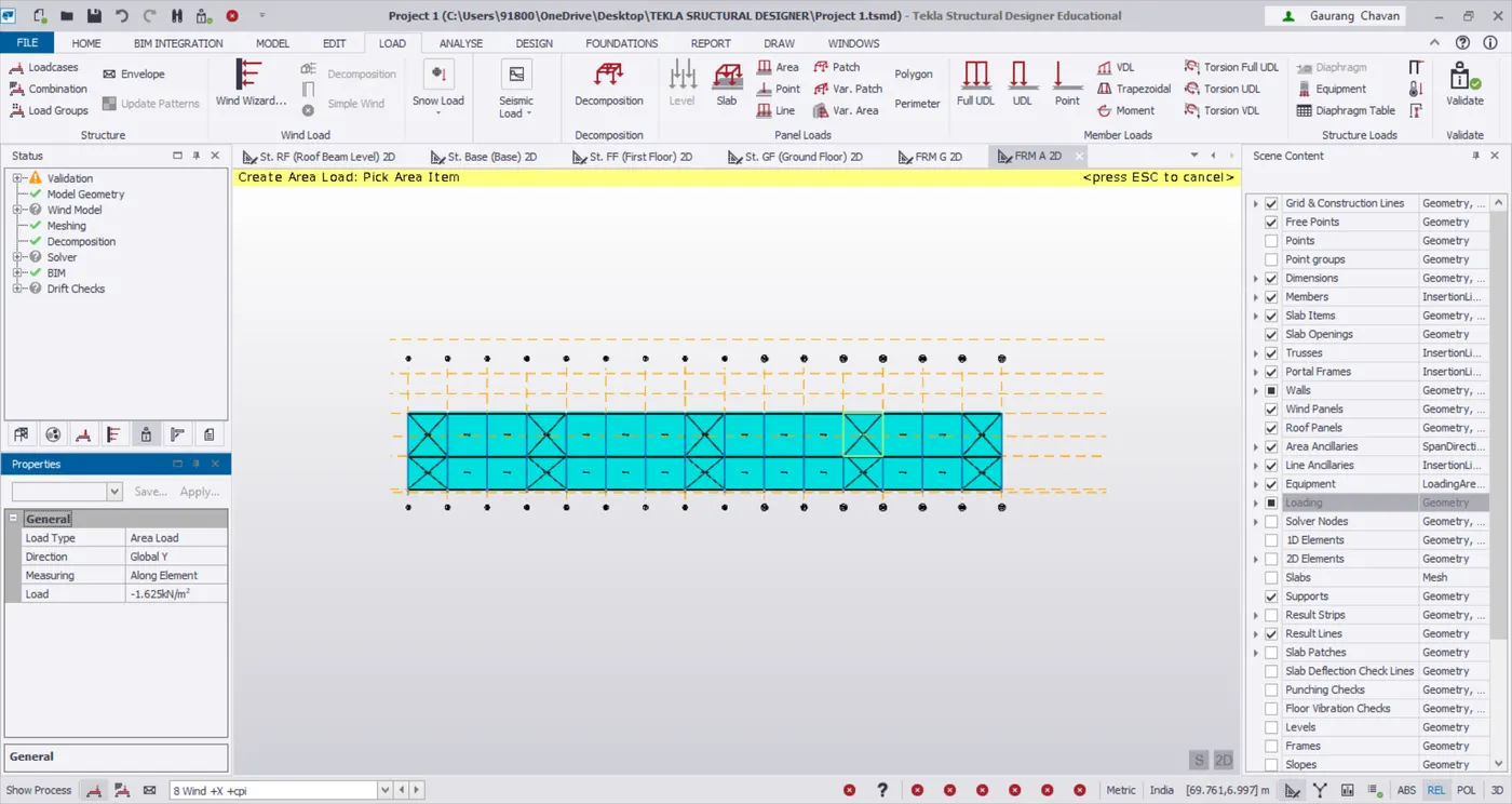
Project 1_Analyze and design a steel building to 10T CRANE as per IS standard code using TEKLA STRUCTURAL DESIGNER.
Aim- To design and analyse a steel building
- Thickness of wall as 150mm
- Wind speed assumption is 39 m/s
- Wall and roof loading is 1.5 KN/m2
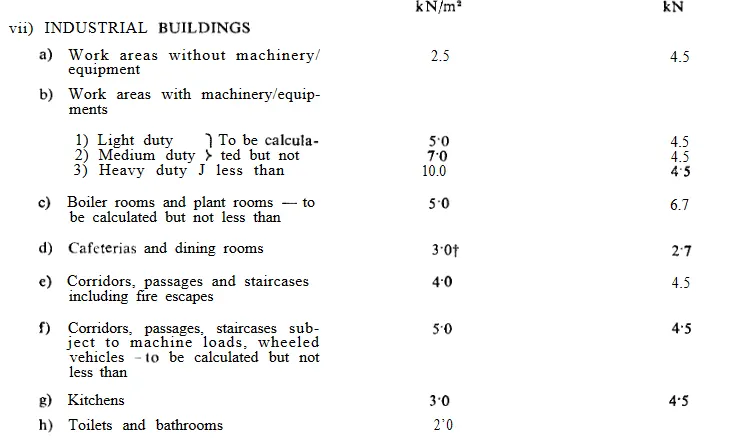
- Live load and euipment loads as per IS 875 Part 2
- Wind load as per IS875 Part 3
Procedure:-
- To model The structure
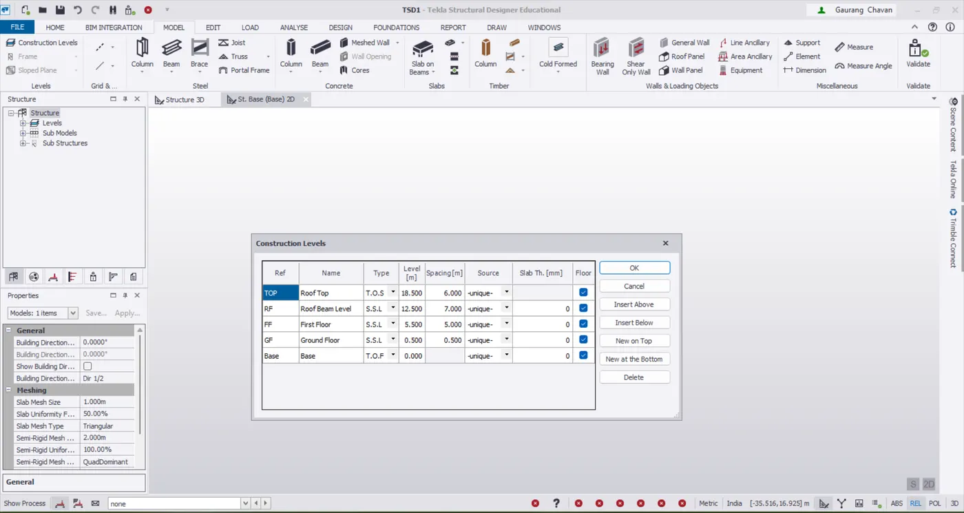
- Define construction levels
- Define levels as per cross section
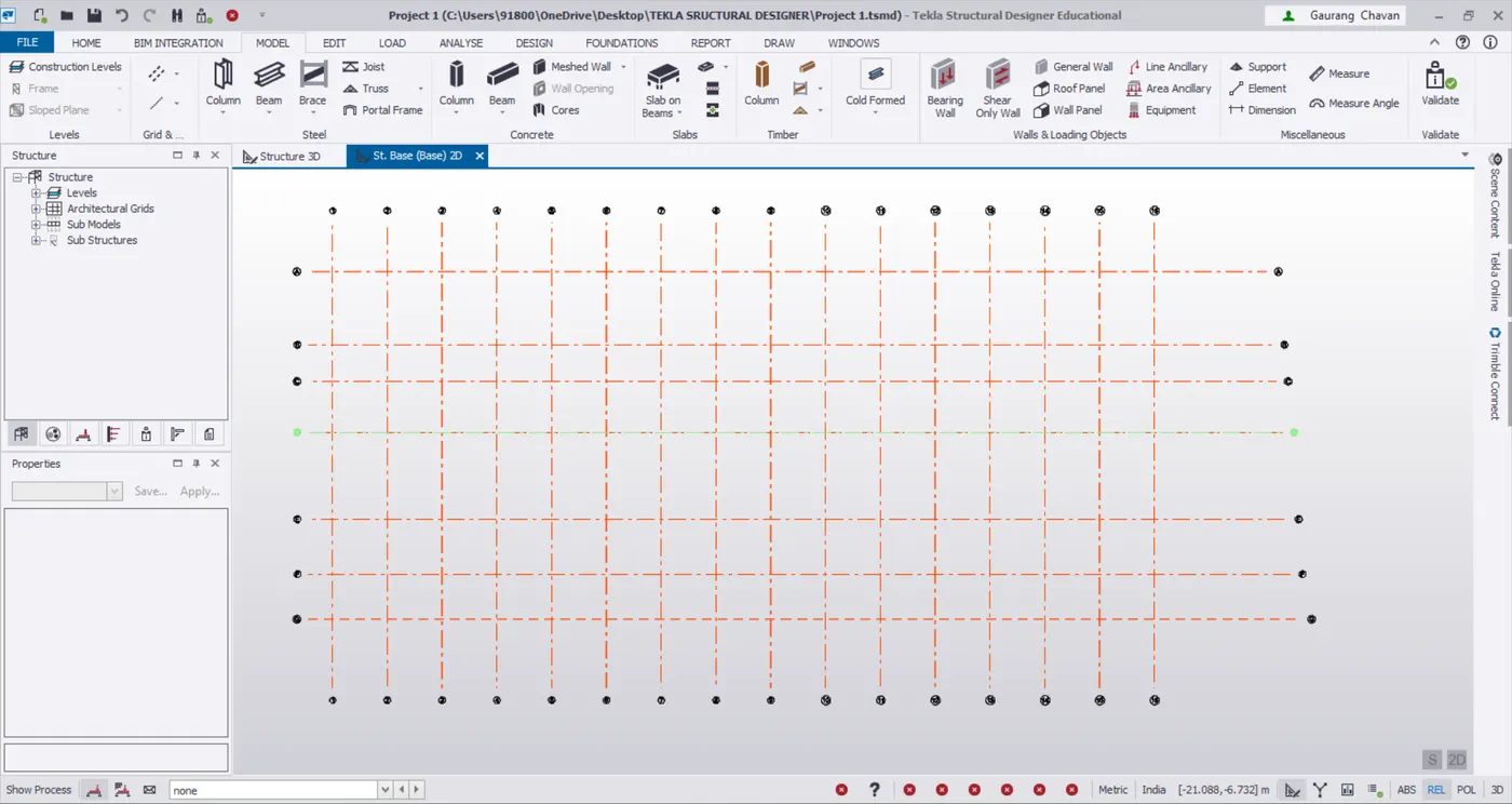
- to define gridlines
- click on gridlines icon in the model toolbar
- specify the first point and draw the first grid line
- then select parallel quick option and draw all other gridlines by specifying the distance
- to add supports to the column base
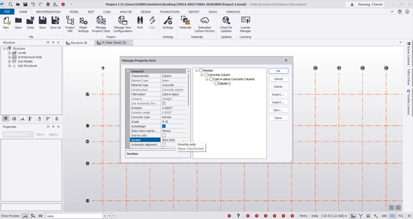
- to add concrete pedastals to the column base
- go to manage property sets from the home toolbar
- click on new> concrete column
- modify the propeties of the concrete column and click on ok
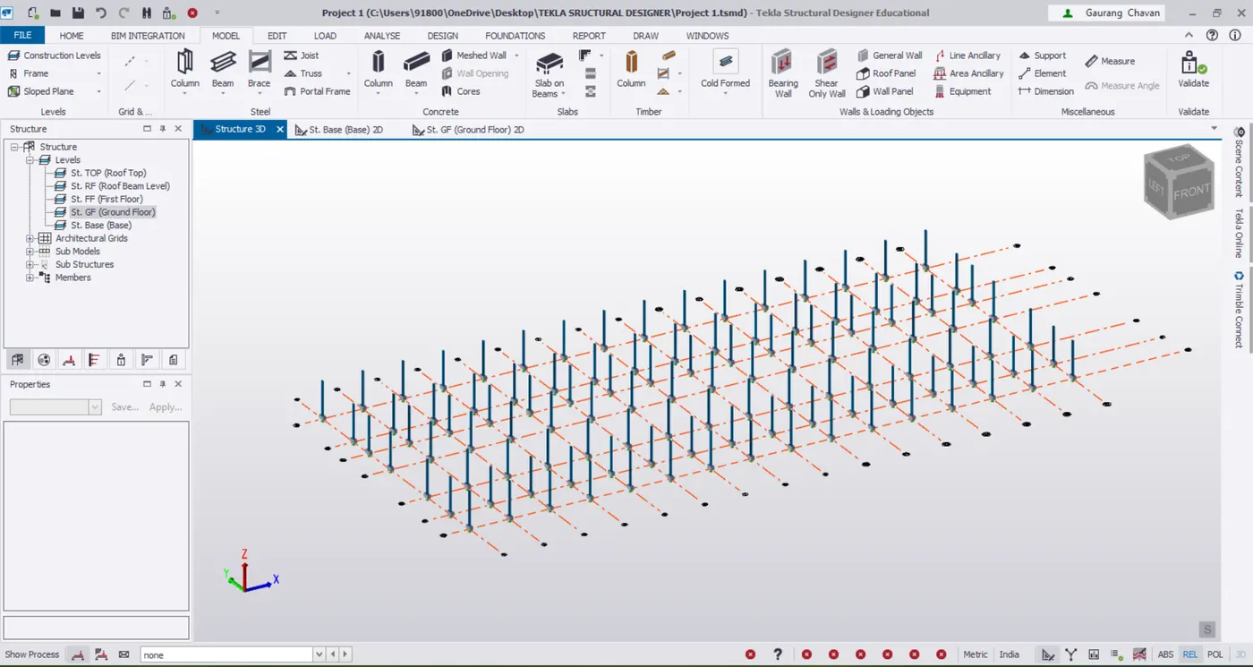
- now go to model>click on column> precast
- select the column properties from the properties dialoguebox
- assign them to the column base
- to assign steel columns
- go to manage property sets>new> steel column
- now select the cross section of the steel column
- add columns to the model
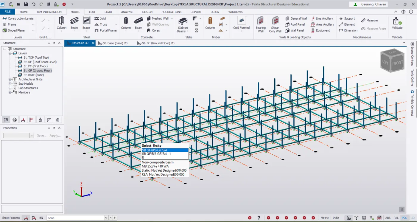
- to model beams
- define the properties of the beam in manage property sets
- assign them to the model
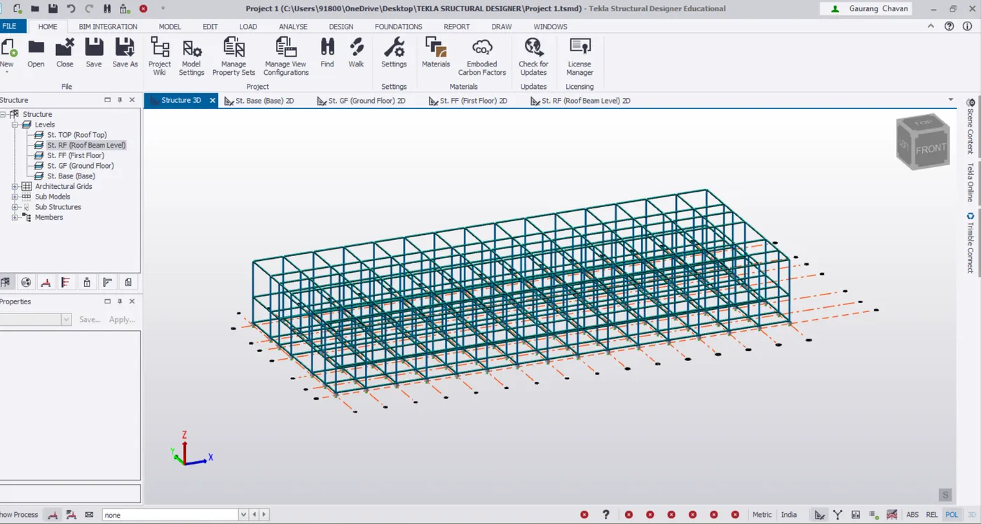
- to add wall panels and roof panels to the model
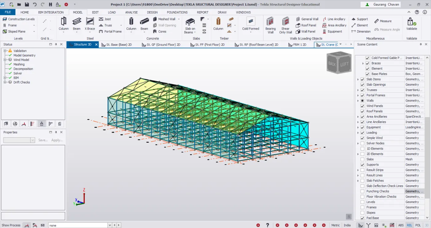
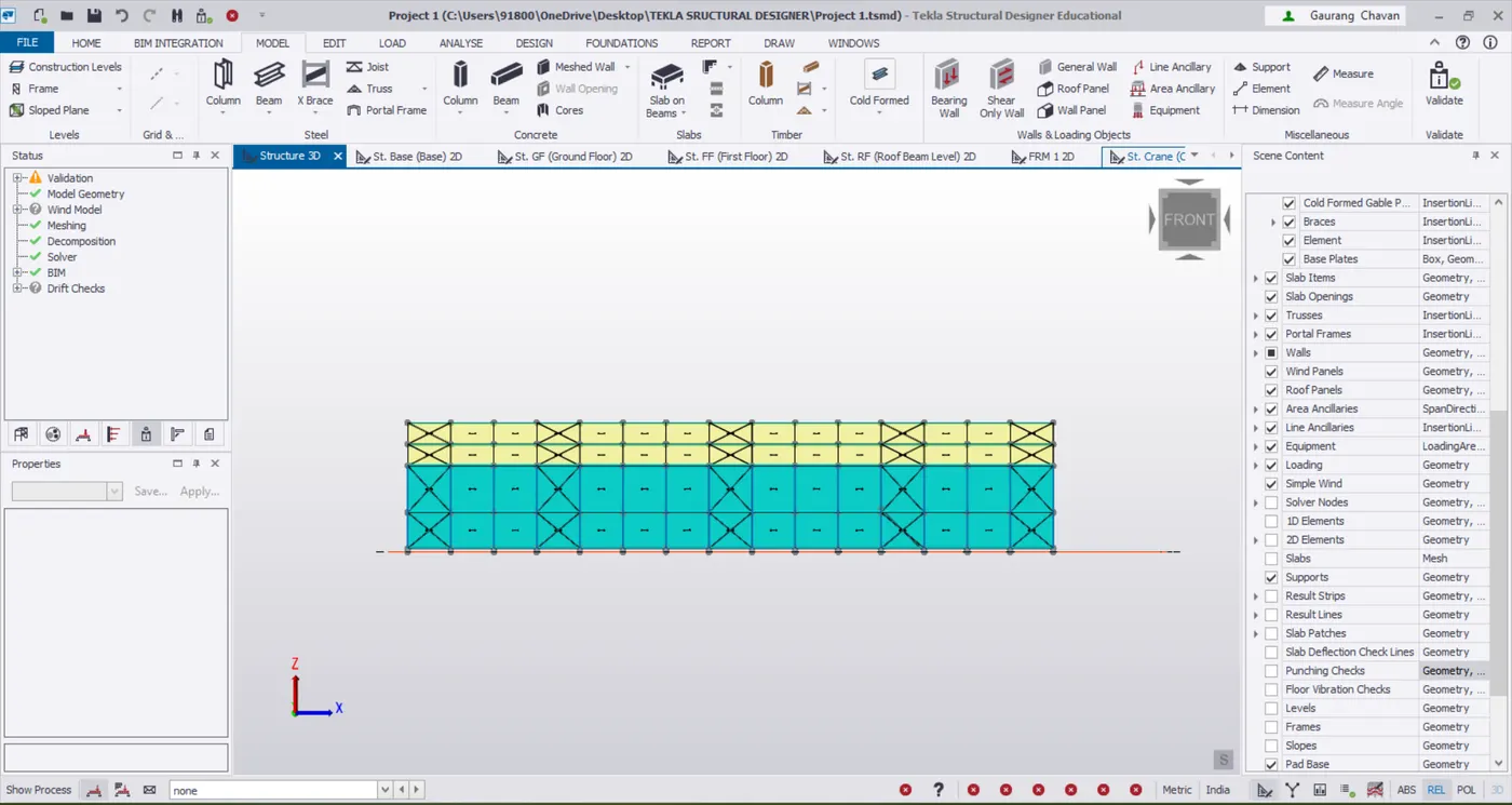
To add slab panels
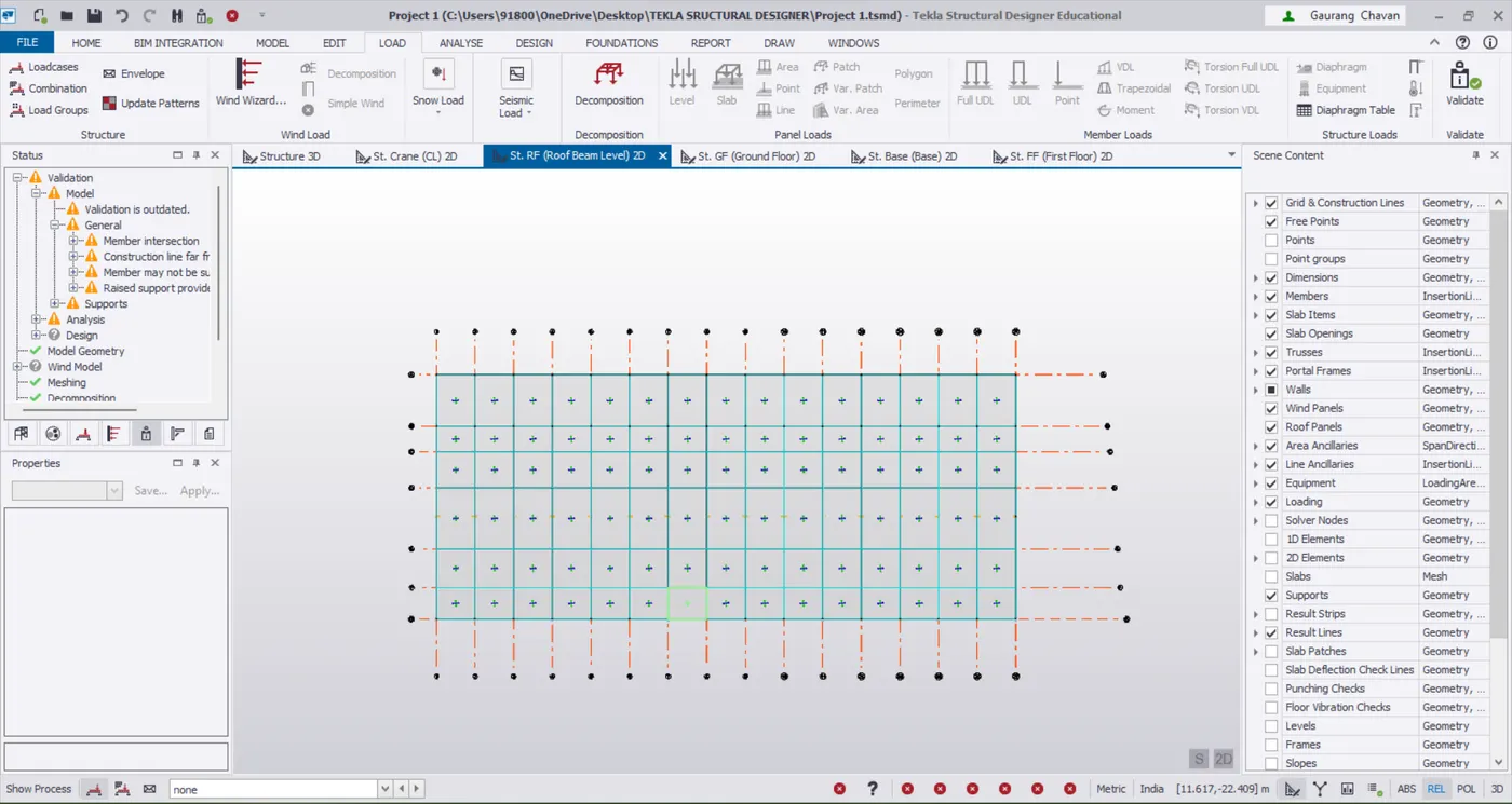
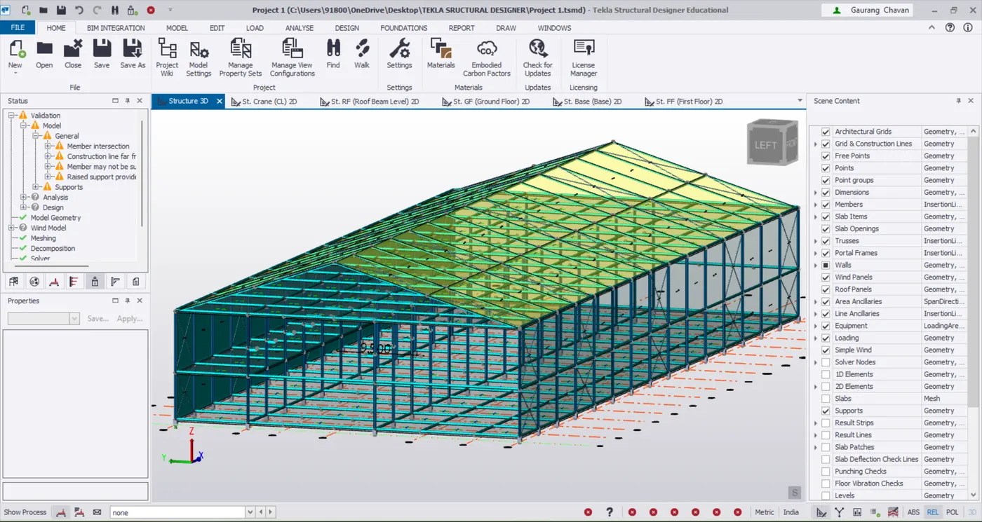
- to add load cases
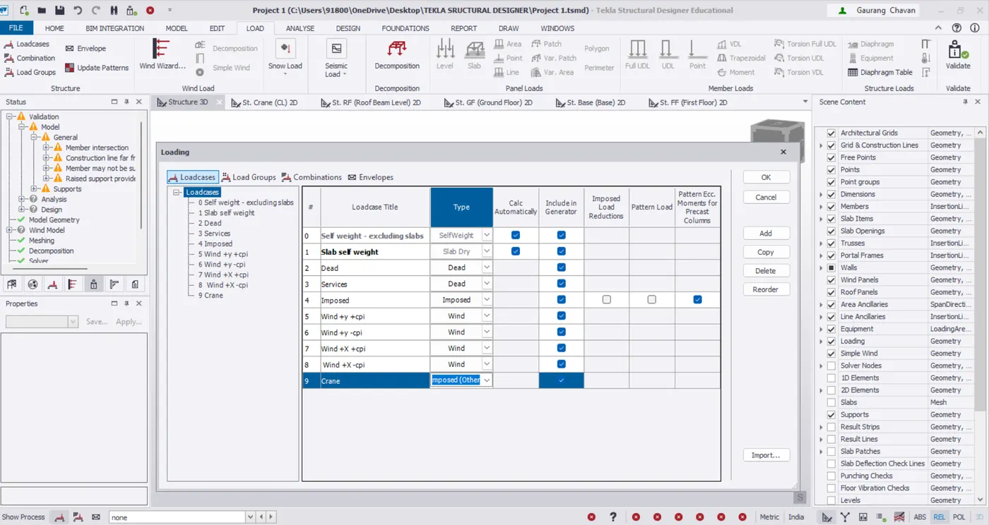
LOAD CALCULATIONS
Calculation of brick wall load
- assume the unit weight of the brick as 20 kn/m^3
- height of the brickwall is 5m
- thickness of the brickwall is 150mm
- load of brick wall is 20 x 5 x 0.15 = 15 kn/m
- brick wall load on first floor beam is 7 x 20 x 0.15 = 21 kn/m
Calculation of floor finishes
- assume the thickness of the floor finishes as 50mm
- unit weight of the floor finishes is assumed as 24 kn/m^3
- floor finishes load is 0.05 x 24 =1.2 kn/m^2
Calculation of imposed loads
- imposed loads are considered as per IS 875 part 2 based on occupany
Calculation of wind loads(as per IS 875 part 3)
- basic wind speed is considered as 39 m/s
- assume the design life of the structure as 50 years
- terrain category as 2
Design wind speed
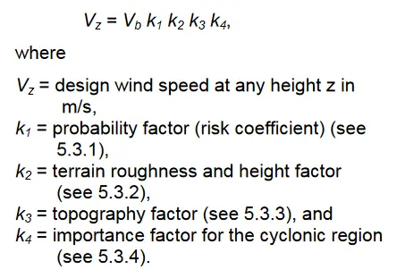
- K1 probability factor is assumed as 1 (as per IS 5.3.1)
- K2 terrain and height factor is assumed as 1
- K3 topography factor is assumed as 1 (for slope of structure greater than 3)
- K4 importance factor for industrial building is taken as 1.15
design wind speed Vz = 39 x 1 x 1 x 1.15 x 1
design wind speed = 44.85
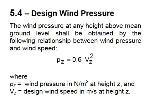
design wind pressure Pz =0.6 x 44.85^2
design wind pressure 1206.9 N/m^2= 1.2 kn/m
- total length of the building is 90m
- width of the structure is 38m
- height of the structure is 12.5m
Ratio of wall and roof co efficients
l/w = 90/38 = 2.36
h/w = 12.5/38 =0.328
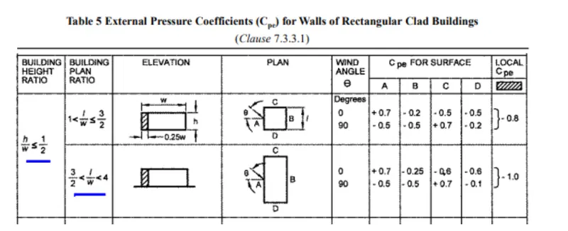
wind load calculations( +Y direction face A )
+Cpi -Cpi
external pressure coefficient 0.7 0.7
internal pressure coefficient 0.7 -0.7
net pressure coefficient 0 1.4
design wind pressure 1.2 1.2
loading to be applied on the wall 0 1.75
wind load calculations( +Y direction face B )
+Cpi -Cpi
external pressure coefficient - 0.25 -0.25
internal pressure coefficient 0.7 -0.7
net pressure coefficient -0.95 0.45
design wind pressure 1.2 1.2
loading to be applied on the wall -1.187 0.562
wind load calculations( +X direction face c )
+Cpi -Cpi
external pressure coefficient - 0.6 -0.6
internal pressure coefficient 0.7 -0.7
net pressure coefficient 1.3 0.1
design wind pressure 1.2 1.2
loading to be applied on the wall -1.625. 0.125
wind load calculations( +X direction face D )
+Cpi -Cpi
external pressure coefficient - 0.6 -0.6
internal pressure coefficient 0.7 -0.7
net pressure coefficient -1.3 0.1
design wind pressure 1.2 1.2
loading to be applied on the wall -1.625. 0.132
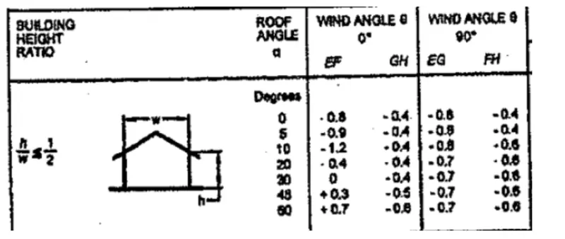
wind load calculations( +y direction face EF )
+Cpi -Cpi
external pressure coefficient - 0.4 -0.4
internal pressure coefficient 0.7 -0.7
net pressure coefficient -1.1 0.3
design wind pressure 1.2 1.2
loading to be applied on the wall -1.375. 0.375
wind load calculations( +y direction face GH )
+Cpi -Cpi
external pressure coefficient - 0.4 -0.4
internal pressure coefficient 0.7 -0.7
net pressure coefficient -1.1 0.3
design wind pressure 1.2 1.2
loading to be applied on the wall -1.375. 0.375
Crane load calculations:-
crane capacity =100kn
weight of the crab = 35kn
weight of the crane = 160kn
max hook approach = 1m
wheel base= 3m
distance between c/c gantry rails =20m
distance between c/c gantry columns= 6m
max point load on the crane = 100 +35= 135
self weight of the crane = 160/2 = 80