Creating a Floor plan, Footing detail and Isometric view using AutoCad
AIM:
To Creating a Floor plan, Footing detail and Isometric view using AutoCAD.
INTRODUCTION:
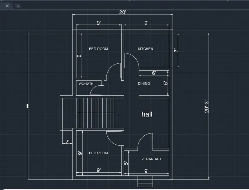
The main objective of this assignment is to get in touch with various tools in AutoCAD like the rectangle, polylines, modifications tools like copy, move, offset and modes like snap mode and ortho mode. These tools will be understood by creating a footing detail, a 2bhk plan & foundation details and isometric view of steps.
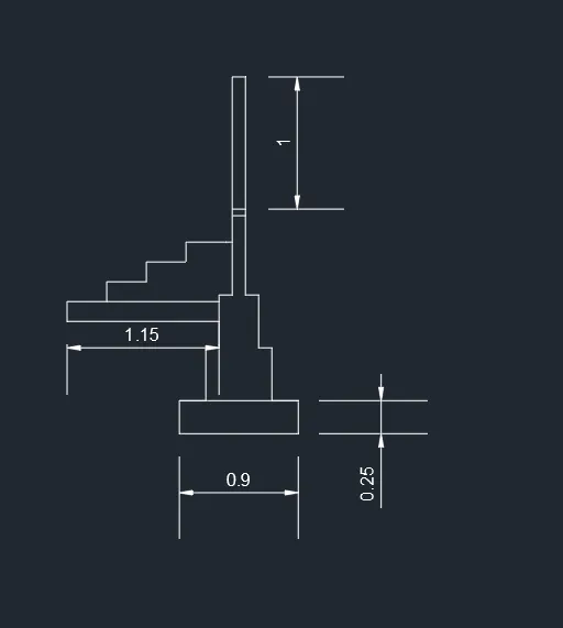
The step by step procedure for drawing C.S of Load bearing wall over spread footing is as follows.
PROCEDURE:
|
Type Rec or Rectangle in the command line and press Enter. Specify the first corner of the rectangle. Enter D for Dimensions. Enter the length: .90 Enter the width: .25 Specify the other corner. Type L in the command line and press Enter. Specify the start point a. Specify next point: @.20, 0 Specify next point:@0, .40 Specify next point:@.05,0 Specify next point:@0, .40 Specify next point:@.05, 0 Specify next point:@0, .60 Specify next point:@.30, 0 Specify next point:@0, -.60 Specify next point:@.05, 0 Specify next point:@0, -.40 Specify next point:@.05, 0 Specify next point:@ 0,-.40 Type L in the command line and press Enter. Specify the start point b. Specify next point: @0, .05 Specify next point:@.30, 0 Specify next point:@0,-.05 Type L in the command line and press Enter. Specify the start point c. Specify next point: @0, 1 Specify next point:@.30, 0 Specify next point:@0,-1 Type L in the command line and press Enter. Specify the start point d. Specify next point: @-.30, 0 Specify next point:@-.05, 0 Specify next point: @-1.15, 0 Specify next point:@0, -.15 Specify next point:@1.15, 0 Type L in the command line and press Enter. Specify the start point e. Specify next point: @.30, 0 Specify next point:@0, .15 Specify next point: @.30, 0 Specify next point:@0, .15 Specify next point: @.30, 0 Specify next point:@0, .15 Specify next point: @.30, 0
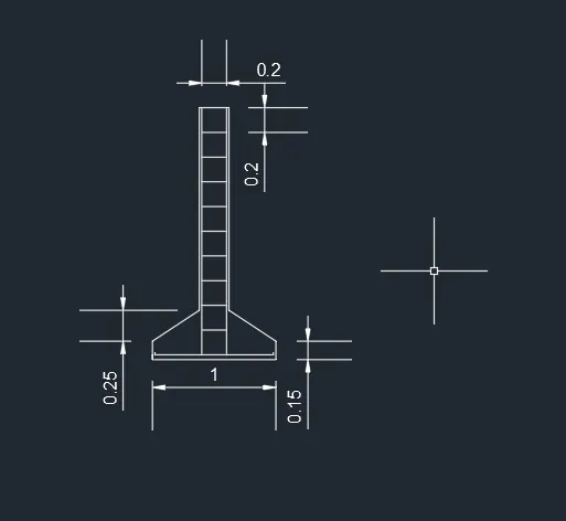
Type L in the command line and press Enter. Specify the start point f. Specify next point: @1, 0 Specify next point:@0, -.60 Specify next point: @-.95, 0 Give the dimensions as per the drawing using dimension command from the command bar. The C.S of Load bearing wall over spread footing is completed. The step by step procedure for drawing C.S of isolated footing is as follows. PROCEDURE: Type Rec or Rectangle in the command line and press Enter. Specify the first corner of the rectangle. Enter D for Dimensions. Enter the length: 1 Enter the width: .40 Specify the other corner. Type CHA or CHAMFER in the command line and press enter Enter D for Distance Specify first chamfer distance:.25 Specify second chamfer distance:.38 Select the first line ab and second line as bc Repeat the same step on opposite side on line cd and bc Delete line ef Type L in the command line and press Enter. Specify the start point e. Specify next point:@0, 1.60 Specify next point:@.24, 0 Specify next point:@0, -1.60 Type L in the command line and press Enter. Specify the start point g. Specify next point:@.04, 0 Specify next point:@0, -1.96 Specify next point:@-.38,0 Specify next point:@0,.04 Type L in the command line and press Enter. Specify the start point h. Specify next point:@-.04, 0 Specify next point:@0, -1.96 Specify next point:@.38,0 Specify next point:@0,.04 Type L in the command line and press Enter. Specify the start point i. Specify next point:@.12, 0 Type O or offset on the command line and press Enter. Specify the value of offset distance:.20 Select the object to offset ij (We need to select the line ij with a small square cursor.) Move the cursor inside to place the line and continue till required. Give the dimensions as per the drawing using dimension command from the command bar. The C.S of the isolated footing is completed
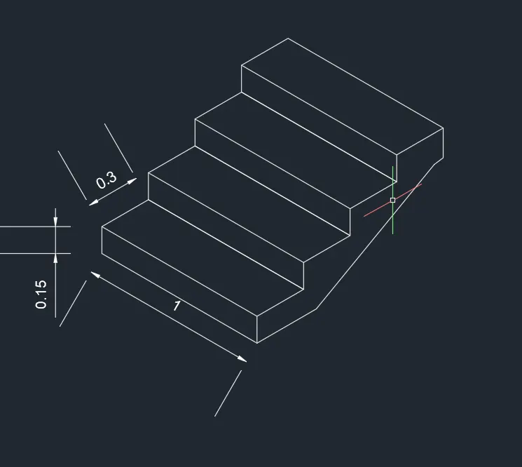
Isometric view of steps. Aim: To draw the isometric view of steps. Commands used:
Procedure:
Step :1 - From isometric drafting select iso-plane left.
Step:2 - Change the isometric drafting to iso-plane top
Step:3 - Change the isometric drafting to iso-plane right
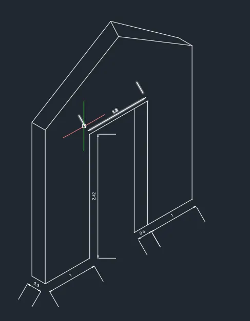
Step:4 - With iso-plane right join the two ends with ortho off. Result: The steps are drawn in isometric view. Isometric view of gable wall. Aim: To draw the isometric view of gable wall. Commands used:
Procedure:
Step:1 - From isometric drafting select iso-plane left.
Step:2 - Using isometric right, take line command and draw line upwards of 2.42 units from the starting point of step 1
Step 3 – Using iso-metric right with the line command draw 1.0 unit to right Side and 3.0 units upwards. Step:4 - By using the line command draw a line from bottom left corner @1.5 units and extend line 4 units upwards i.e., total 3.25 units from bottom. Step :5 - With ortho off, draw a line between the corner of left side and the projected line done in step 4
Step:6 - Draw the vertical line with ortho on @0.3 and join the vertical line using line from left and right end same as in the step 5 remove unwanted lines by using erase. Result: The isometric view of gable wall is draw
|