Project 1_Analyze and design a steel building to 10T CRANE as per IS standard code using TEKLA STRUCTURAL DESIGNER.
Question. Analyze and design a steel building to 10T CRANE as per IS standard code in TEKLA STRUCTURAL DESIGNER. Refer the attached plan and elevation. Provide bracings and moment connection for lateral stability.
Consider dead, live, equipment and wind loading. Consider the brick wall loading for 150mm thick and 1.5 KN per sq.m for wall and roof cladding.
Assume wind loading basic speed as 39m/s.
Report of each member to be generated and extract drawings of structural plans from the software.
Solution:
AIM: To analyze and design a steel building to 10T CRANE as per IS standard coded in TEKLA STRUCTURAL DESIGNER.
PROCEDURE:
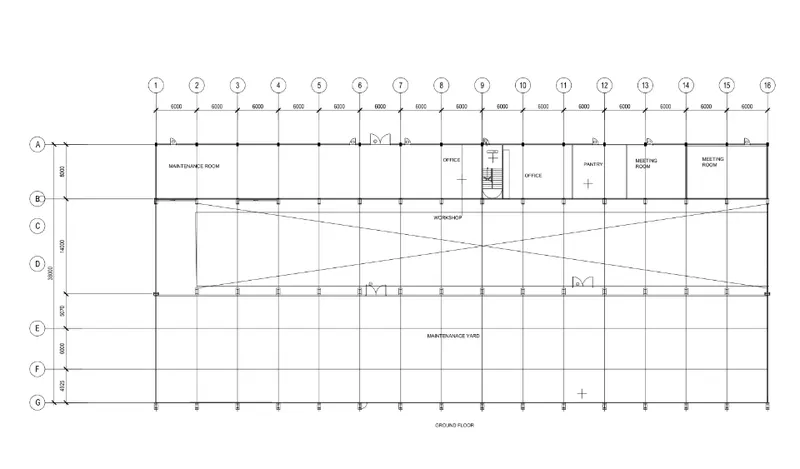
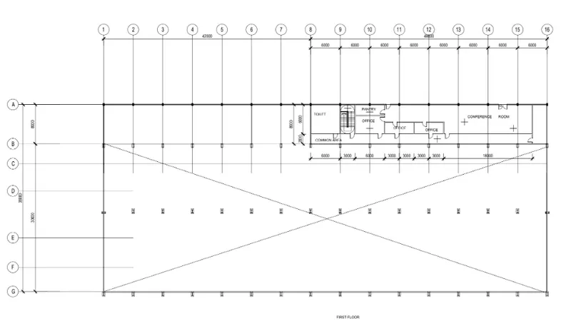
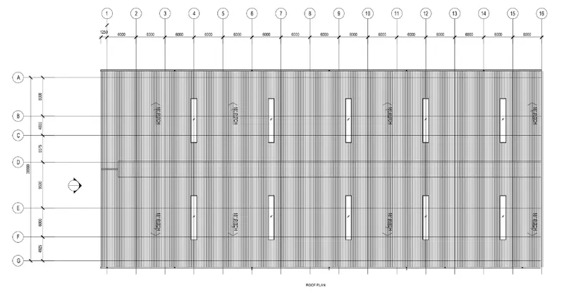
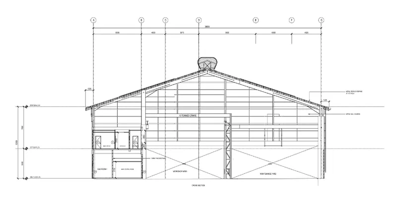
- We need to design a steel building to 10T CRANE for the below plan and the cross-sections:
Ground floor Plan:
First Floor Plan:
Roopf Plan:
Cross-Section of the steel building:
- First of all we need to open the TEKLA STRUCTURAL DESIGNER (TSD) software.
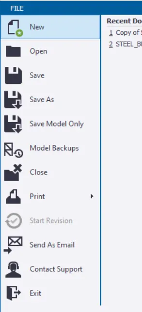
- After opening the TSD software, there will be a tab File tab just click on that option then there will be a drop-down list and in that list there will be an option called New just click on that option just as shown in the below given image:
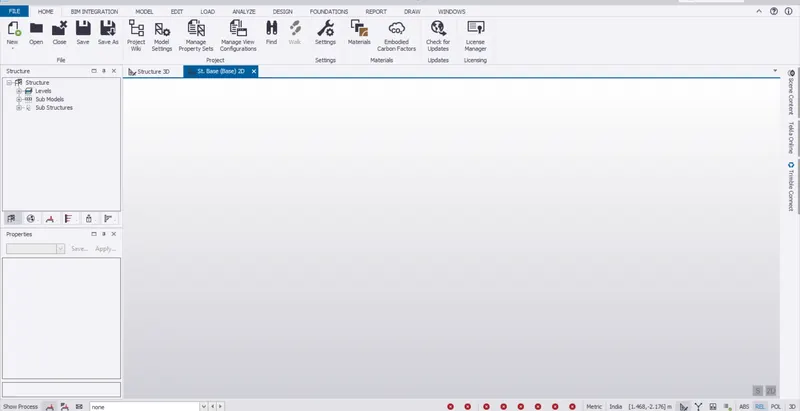
- After this there will be a new workplace that has been created as shown in the below given image:
- After this adjust the settings accordingly.
GRIDS:
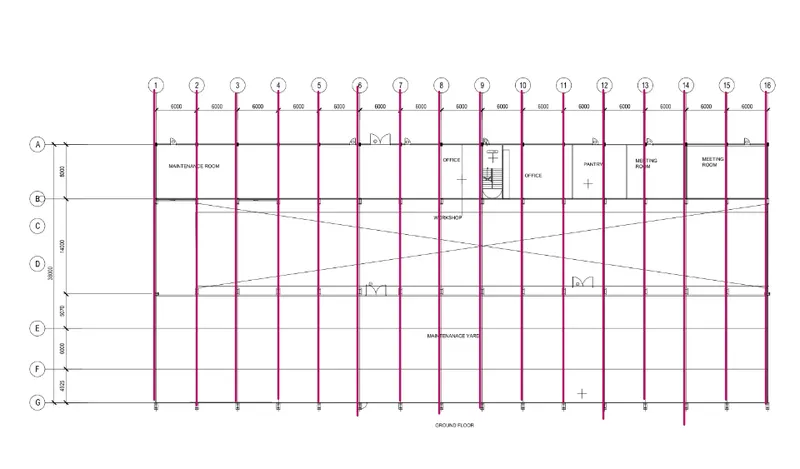
- The next step iis to create the grid lines according to the plan of the building.
- The red lines are the vertical grids just as shown in the below given image:
- Now we will be creating the vertical grid lines and to create grid lines go to the option Model tab just click on that option and in that tab there are multiple options as we can see in the below given image:

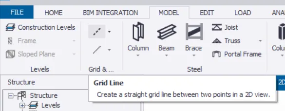
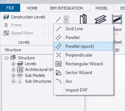
- Now there will be an option named as the Grid Lines and at the side there will be an arrow just click on that just as shown in the below given image:
- Just create the first grid line using the Grid Line tool just as shown in the below given image:
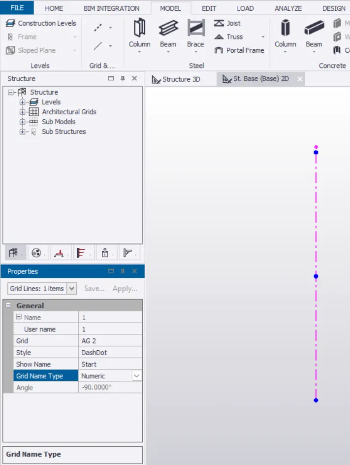
- And now we will be creating the other grid lines by using the option Parallel (quick) and the remaining step as we have done in the previous step below is the image of the horizontal grid lines:
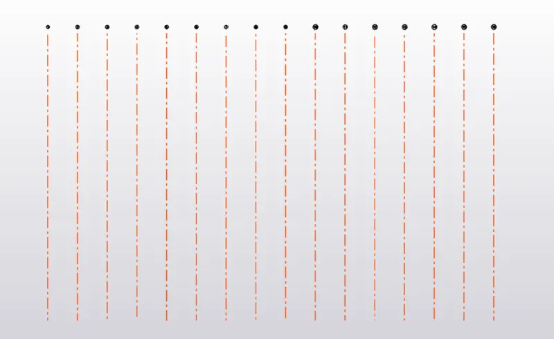
- Below is the vertical grid lines created in the image:
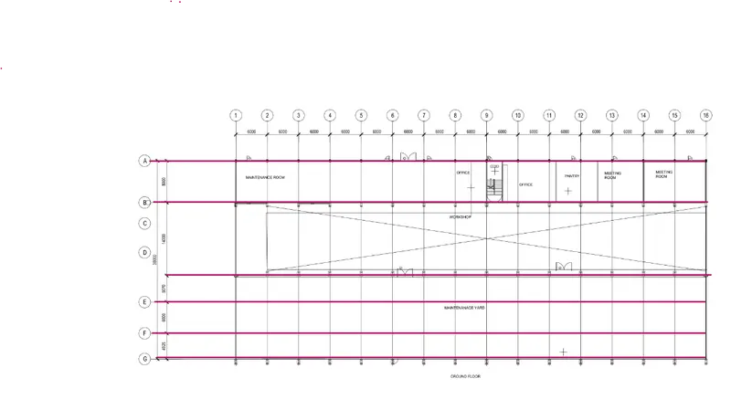
- The red lines are the vertical grids just as shown in the below given image:
- Now we will be creating the horizontal grid lines and to create grid lines go to the option Model tab just click on that option and in that tab there are multiple options as we can see in the below given image:
- Now there will be an option named as the Grid Lines and at the side there will be an arrow just click on that just as shown in the below given image:
- Just create the first grid line using the Grid Line tool just as shown in the below given image:
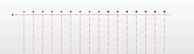
- And now we will be creating the other grid lines by using the option Parallel (quick) and the remaining step as we have done in the previous step below is the image of the horizontal grid lines:
- Below is the horizontal and vertical grid lines created in the image:
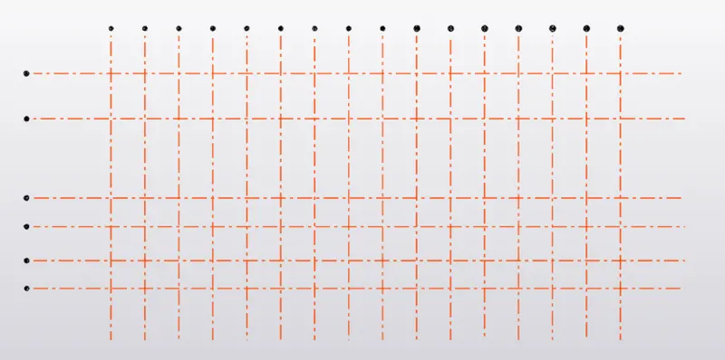
- Now we are done with the grid-lines and now we will be creating the construction levels.
Construction Level:
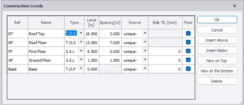
- So the next step in the modelling the structure is to model construction level.
- And in order to create the construction level we need to first go to the Model tab and in that tab there will be an option called construction level just click on that option as shown in the below given image:

- After that there will be another dialouge box named as the Construction level in that dialouge box create the levels according to the cross-section of the plan just as shown in the below given image:
Pedestal Column:
- Now we will be going to create the pedestal column and in order to create the pedestal column first we need to go to the Home tab then there will be multiple options and in those option there will be an option called Manage Property Sets just click on that option just as shown in the below given image:

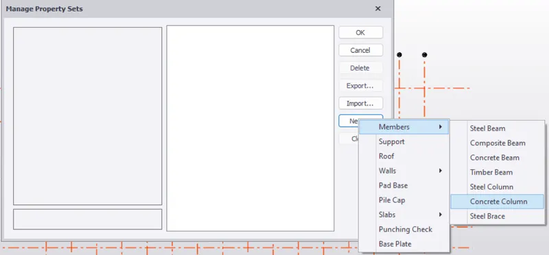
- After that there will be a dialouge box named as the Manage Property Sets and in that dialouge box on the right side of the dialouge box there will be many options and in those options there is an option named New just click on that option.
- After clicking on the New option there will be a drop-down list and in that list there will be an option called Members just click on that then there will be another drop-down list and in that list there will be another option named as the Concrete Column just click on that option just as shown in the below given image:
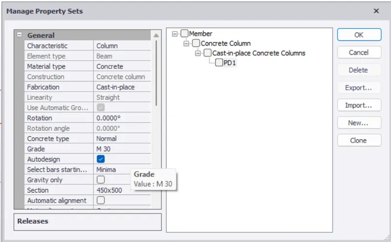
- Now rename it as PD1 and adjust the properties according to the given plan just as shown in the below given image:
- After that we will be placing the pedestal column in the plan just go to Model tab click on that then there will be an option in the model tab named as the Column just click on that option just as shown in the below given image:

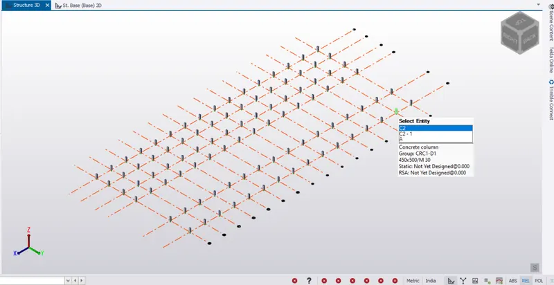
- Now adjust the properties according to the PD1 and we will be creating the pedestal column from base upto the ground floor just as shown in the below given image:
Steel Columns:
- Now the next step is to create the steel column and in order to create the steel column first we need to go to the Home tab then there will be multiple options and in those option there will be an option called Manage Property Sets just click on that option just as shown in the below given image:
-
- After that there will be a dialouge box named as the Manage Property Sets and in that dialouge box on the right side of the dialouge box there will be many options and in those options there is an option named New just click on that option.
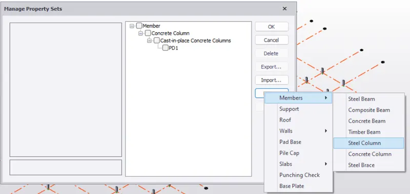
- After clicking on the New option there will be a drop-down list and in that list there will be an option called Members just click on that then there will be another drop-down list and in that list there will be another option named as the Steel Column just click on that option just as shown in the below given image:
- And rename it as C1 just as shown below:
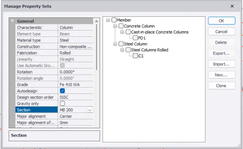
- Now select the section according to the plan just as shown in the below given image:
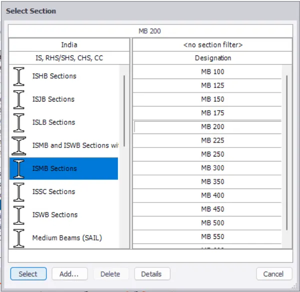
- And then make the steel column from ground floor upto the roof floor and arrange the properties accordingly just as shown in the below given image:
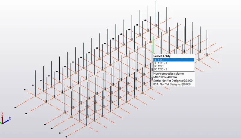
Beams:
- Now we will be modelling the beams in the structure.
- So first of all go to the Home tab then there will be multiple options and in those option there will be an option called Manage Property Sets just click on that option just as shown in the below given image:
- After that there will be a dialouge box named as the Manage Property Sets and in that dialouge box on the right side of the dialouge box there will be many options and in those options there is an option named New just click on that option.
- After clicking on the New option there will be a drop-down list and in that list there will be an option called Members just click on that then there will be another drop-down list and in that list there will be another option named as the Steel Column just click on that option just as shown in the below given image:
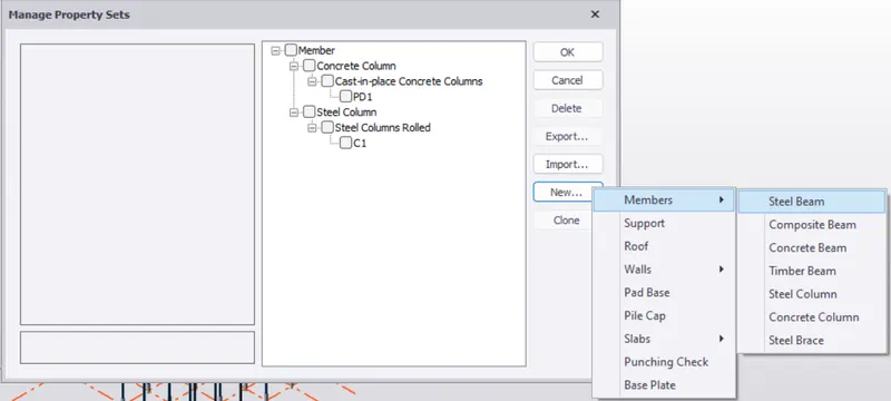
- And rename it as B1 just as shown below:
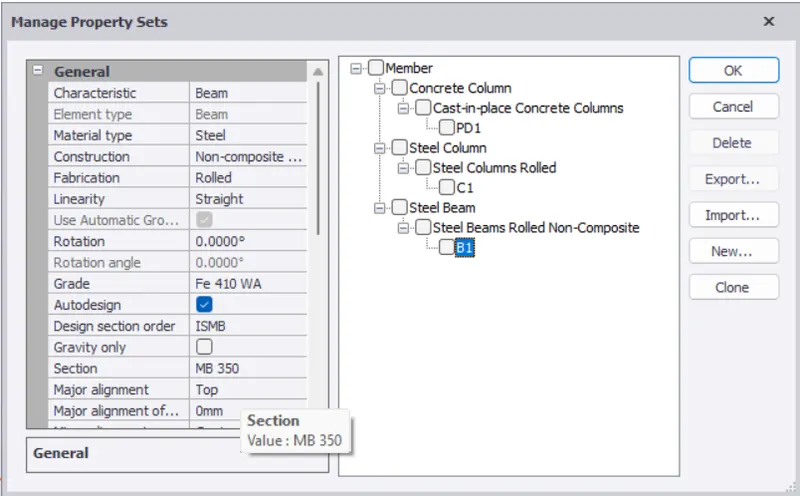
- And in order to model the beams in the plan first we need to go to the Model menu just click on that option after that there will be an option named as beams just click on that option just as shown in the below given image:

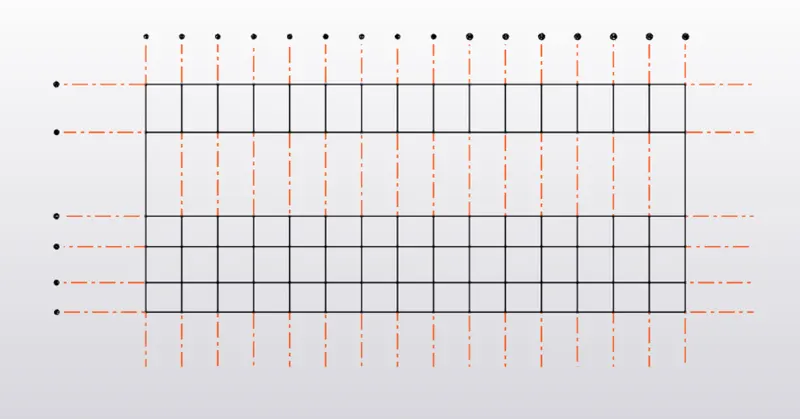
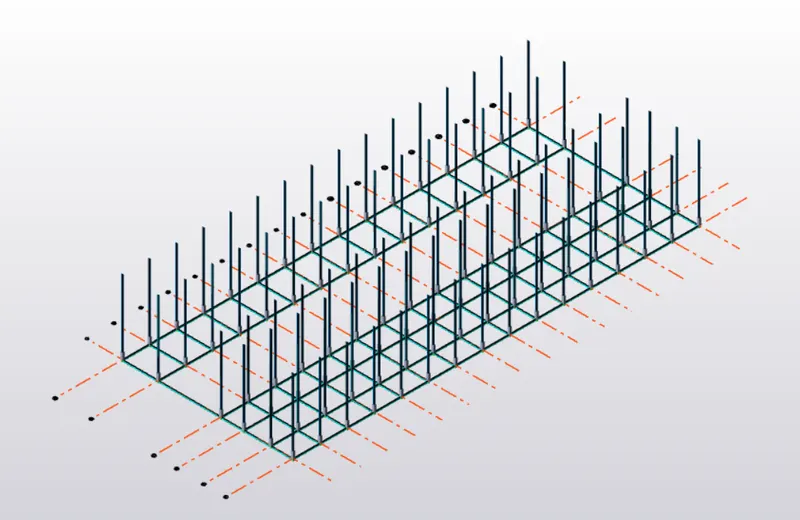
- Now model the beam just as shown in the below given image:
Ground Floor Beam Plan:
- In order to draw the beams in the first floor draw some construction lines in order to make some secondary beams.
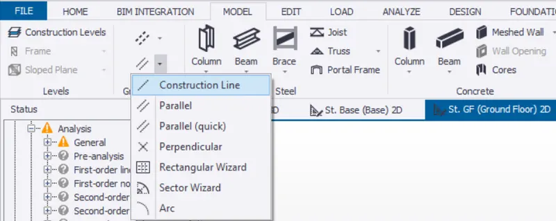
- And in oeder to draw the construction beams go to the Model tab then there will be an option called Construction Lines just click on that option just as shgown in the below given image:
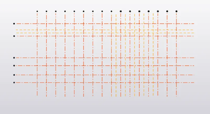
- Now draw the construction lines according to the plan just as shown in the below given image:
First Floor Beam Plan:
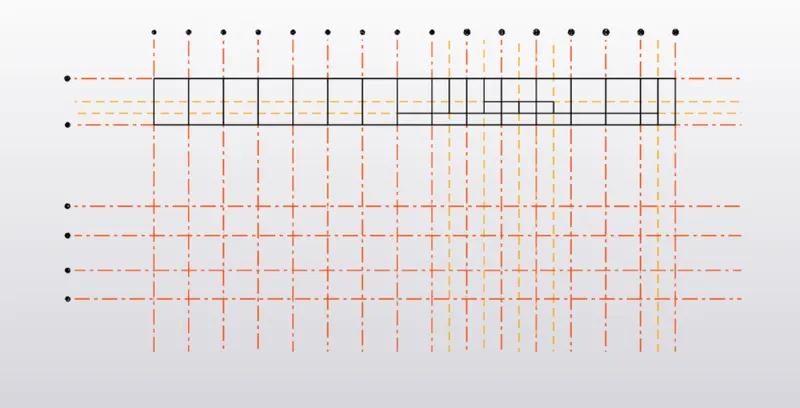
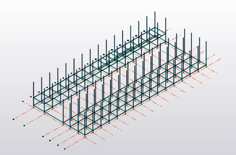
Roof Floor Plan:
- Repeat the same procedure as we have already done for the other beams.
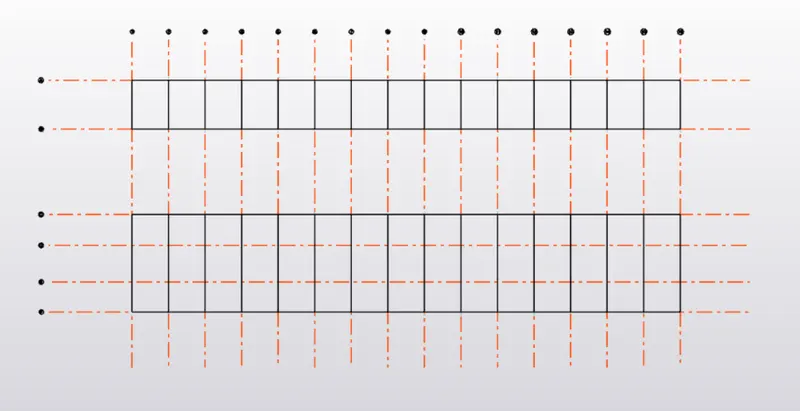
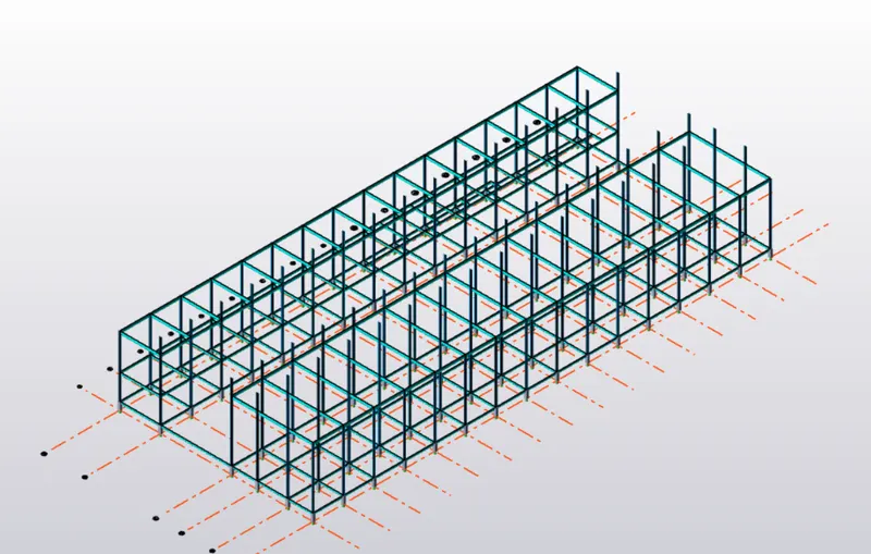
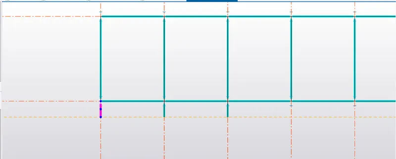
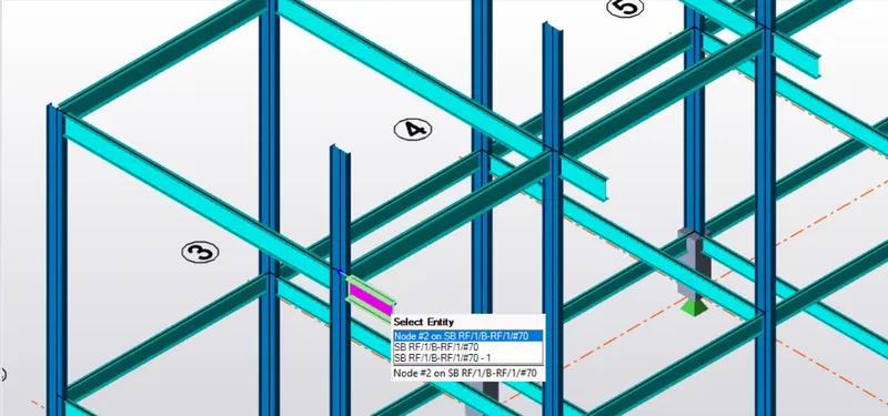
- Now model the beam for the crane as shown in the below given image:
Rafter:
- After modelling the beam now we will be modelling the rafter for the structure and as for modelling the rafter.
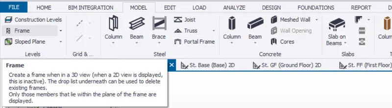
- And in order to modelling the rafter first we need to create the frames and to create the frames first we need to go to the Model tab then there will be another option called Frame just click on that option just as shown in the below given image:
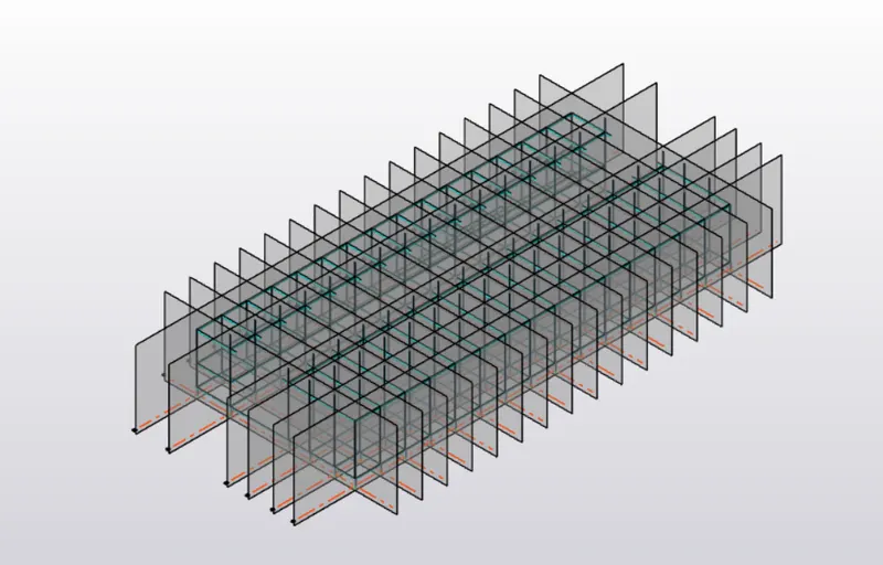
- After that choose the grid lines where we want to create the frames just as shown in the below given image:
- Now select the frame in order to create the rafter just as shown in the below given image:
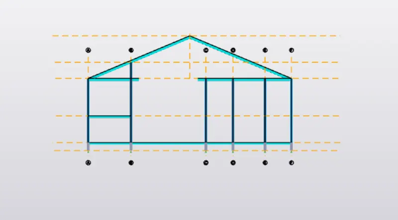
- Now do the same procedure for the remaining the rafters or just copy the modelled rafter just select the rafter right-click and then there will be another drop-down list and in that list there will be an option called Copy just click on that option as shown in the below given image:
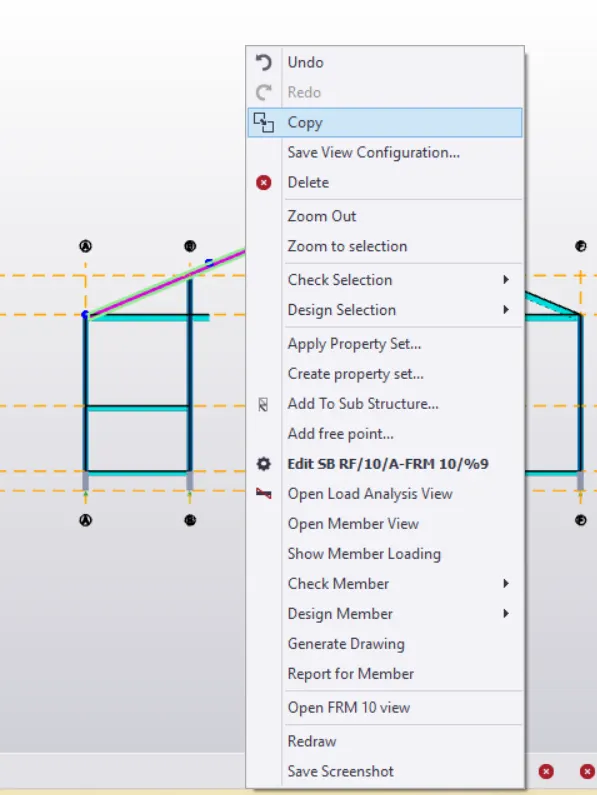
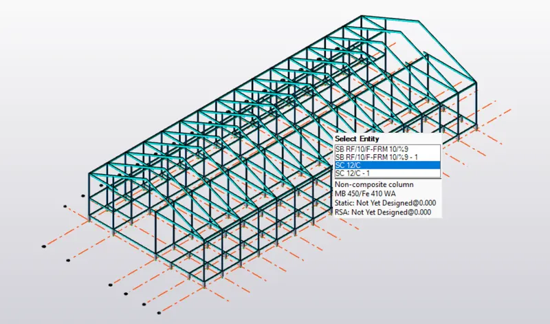
- Now select the first reference point and then paste it at the specific point where we need it just as shown in the below given image:
Steel bracings:
- So after modelling the rafter next we need to model the steel bracing.
- First of all we need to define the properties of the steel bracing and in order to assign the properties first we need to go to the Home tab then there will be an option called Manage Property Set just click on that option just as shown in the below given image:

- Now there will be another dialouge box named as the Manage Property Sets and in that dialouge box there will be an option on the right side of the box named as the New just click on that option then there will be a drop-down list and in that list there will be an option called Members click on that after that there will be another drop-down list and in that list there will be an option named as the Steel Brace just click on that option just as shown in the below given image:

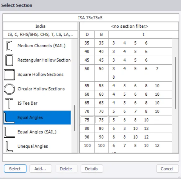
- Now we will be assigning the properties accordingly,first we need to select the section just go to the option on the left side of the box and select the sections just as shown in the below given image:
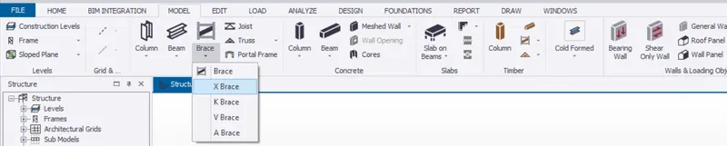
- And in order to model the steel bracing first we need go to the Model tab and in that tab there will be an option called braces just click on that option just as shown in the below given image:
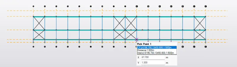
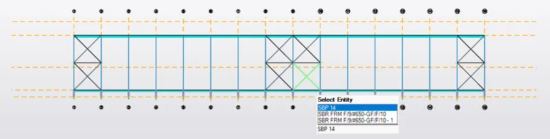
- And now go to the frame where we are going to model the frame,select frame and draw the steel braces just as shown in the below given image:
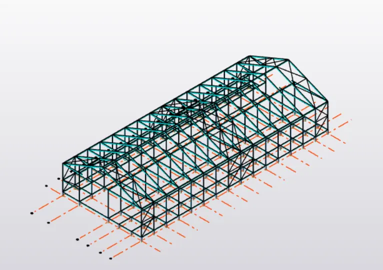
- Now do the same procedure for the roof and in order to model the roof bracings first go to the 3D model view and draw the steel bracings just as shown in the below given imge:
Slabs:
- Now we will be modelling the slabs in the structure.
- Again first go to the Home tab then there will be an option called Manage Property Sets just click on that option just as shown in the below given image:
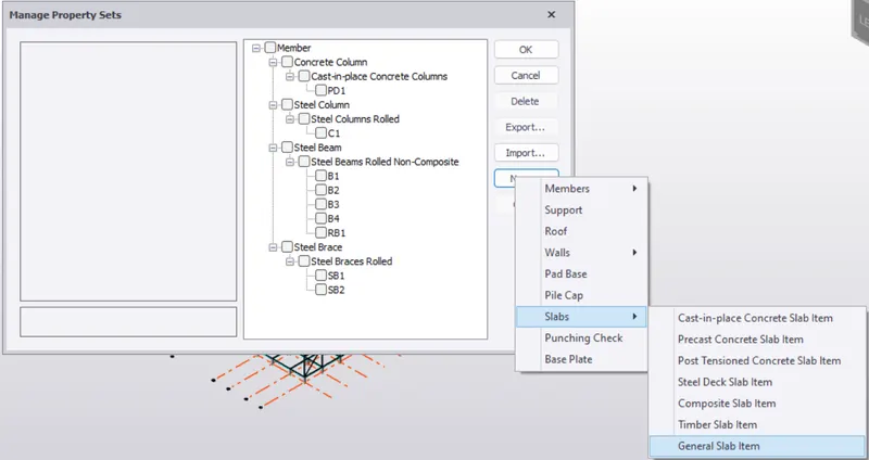
- Now there will be another dialouge box named as the Manage Property Sets and in that dialouge box there will be an option on the right side of the box named as the New just click on that option then there will be a drop-down list and in that list there will be an option called Slabs click on that after that there will be another drop-down list and in that list there will be an option named as the General Slab Item just click on that option just as shown in the below given image:
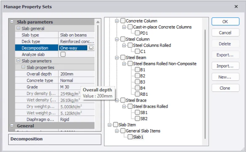
- And now we will be assigning the properties for the slabs like overall depth of the slab,grades etc just as shown in the below given image:
- After assigning the properties for the slab just go to the Model tab then there will be an option named as the Slab on beams just click on that option as shown in the below given image:

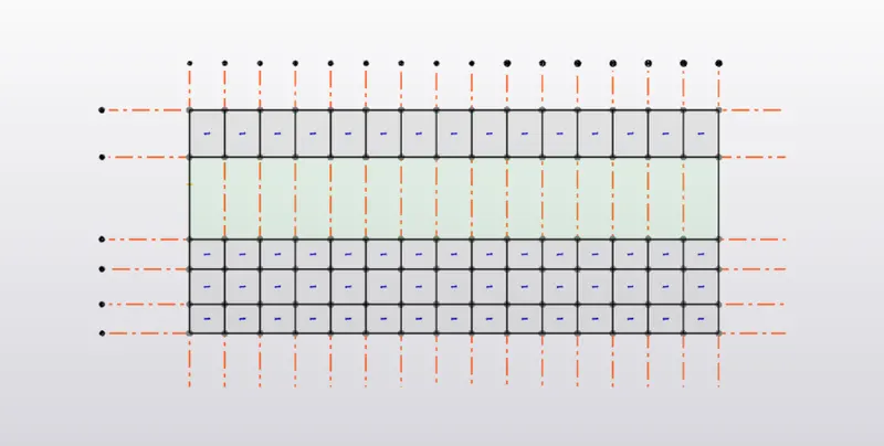
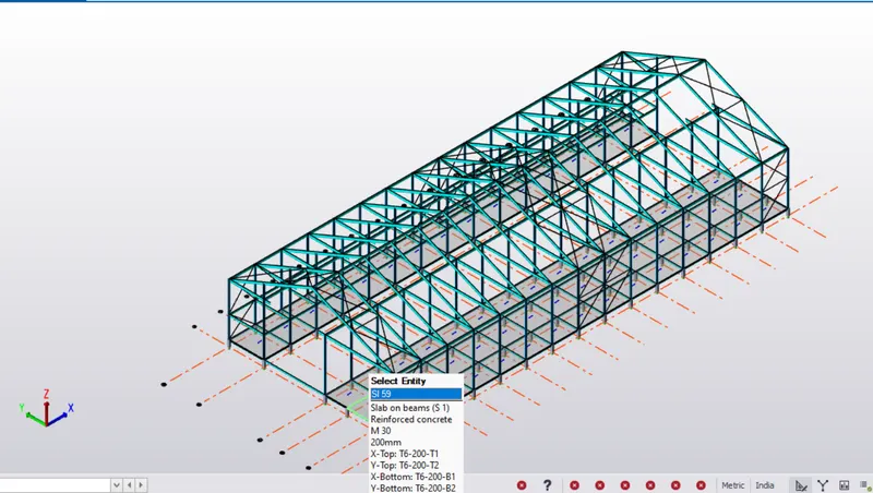
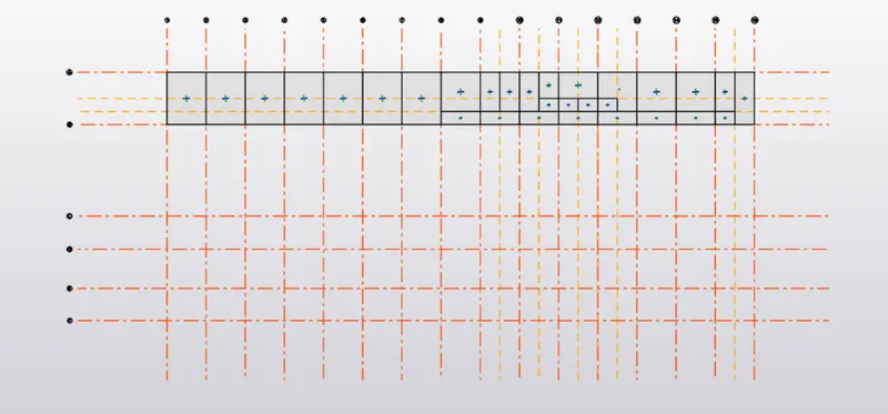
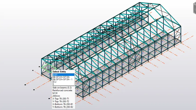
- Now assign the slabs on the floors and the roof just as shown in the below given image:
Ground Floor:
First Floor:
Roof Floor:
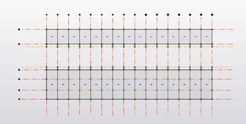
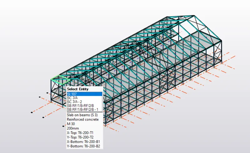
Roof:
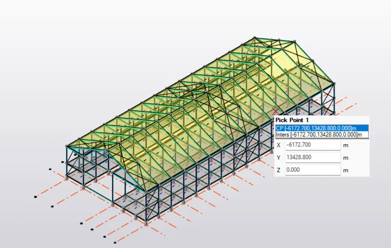
- And now in order to create the roof pannels go to the Model tab there will be an option called Roof pannel just click on that option as shown in the below given image:

- And now create the roof pannels in the 3D-view just by clicking the Roof pannels and select the points and create the roof pannels just as shown in the below given image:
Wall Panel:
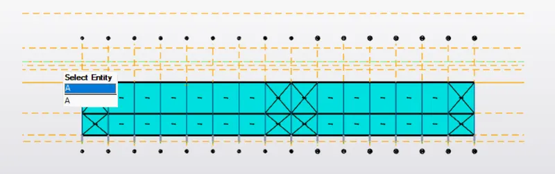
- Now we will be modelling the wall panel and in order to create the wall panel just go to the Model tab then there will be another option named as the Wall panel just click on that option as shown in the below given image:

- Now select the frame where we will be modelling the wall panel as shown in the below given image:
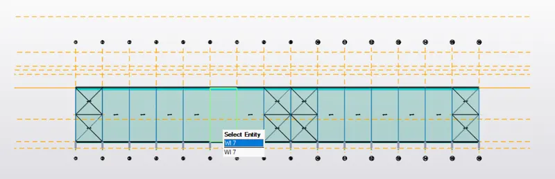
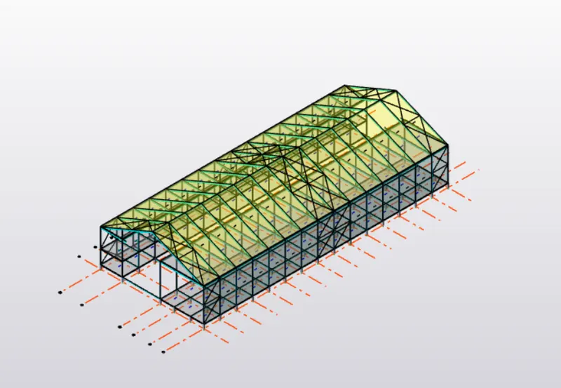
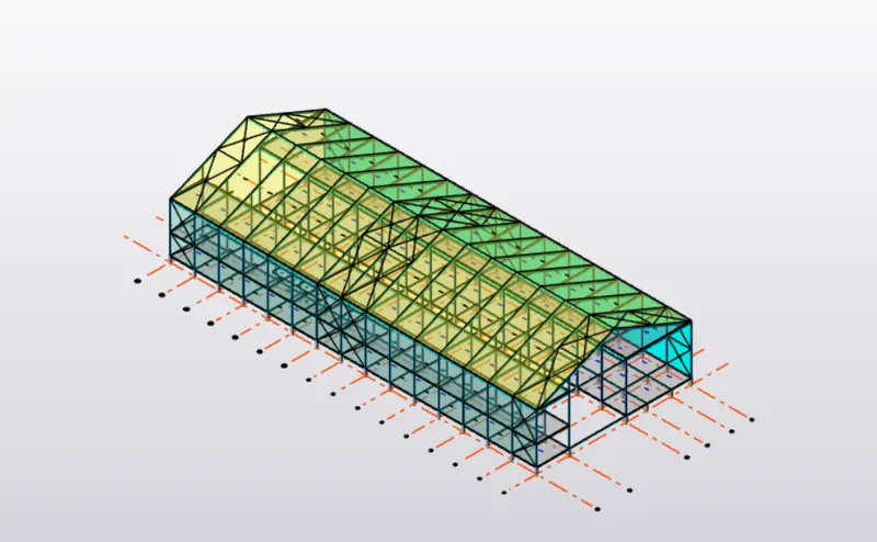
- Now do the same procedure as we have done in the above step and below are the images of the other wall panel:
Manual Calculations for the loads:
Dead Load:
Brick wall thickness = 150mm.
Height of the wall (Ground Floor to First Floor) = 5m.
Height of the wall (First Floor to Roof Level) = 7m.
Finishes = 50mm.
Unit weight = 20kN/cub.m.
Brick wall loading (Ground Floor to First Floor) = Brickwall thickness*Unit-weight*Height of the wall.
Brick wall loading (Ground Floor to First Floor) = 0.15*20*5.
Brick wall loading (Ground Floor to First Floor) = 15kN/m.
Brick wall loading (First Floor to Roof Level) = Brickwall thickness*Unit-weight*Height of the wall.
Brick wall loading (First Floor to Roof Level) = 0.15*20*7.
Brick wall loading (First Floor to Roof Level) = 21kN/m.
Unit-weight of the Concrete = 24kN/cub.m.
Finishes = 50*24
= 0.05*24
= 1.2kN/sq.m.
Floor Height:
Assume the floor finish thickness = 50mm.
Floor Finish = 1.2kN/cu.m.
Roofing load based on the purlin size = 1.5 kN/sq.mm.
Ceiling Load = 0.3kN/sq.m.
- Now we have calculated the Dead loads manually, so applied the loads into the software.
- In order to apply the dead loads into the structure go to the Loads tab in that tab there will be an option named as the Loadcases click on that option just as shown in the below given image:

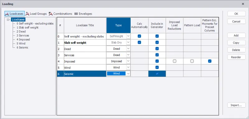
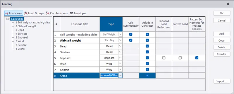
- Now there will be a new dialouge box named as the dialouge box, in that dialouge box add the cases like wind loads, seismic loads, imposed loads, dead loads etc. just as shown in the below given image:
- Now we will be generating the Load combinations so in order to generate the load combinations in the same dialouge box as of the load cases there will be an option named as the Combinations just click on that option.
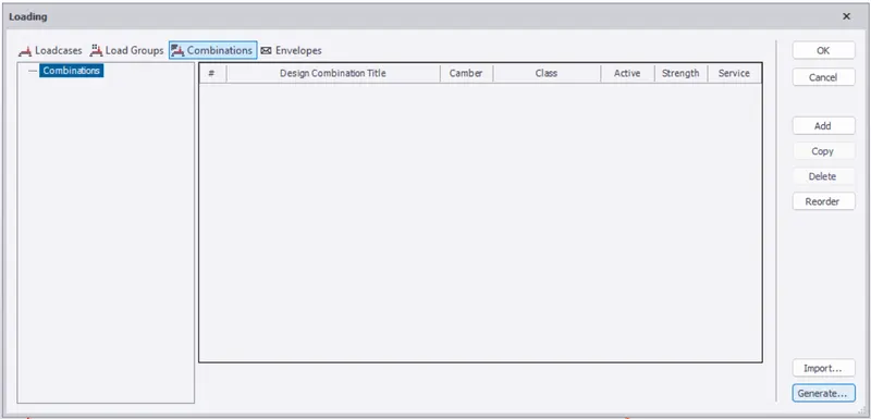
- After that there will be a new page and in that page there will be an option named as the Generate at the right corner of the page just click that option just as shown in the below given image:
- After clicking on the generate option there will be a list of the generated combinations just as shown in the below given image:
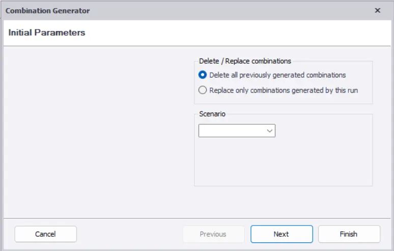
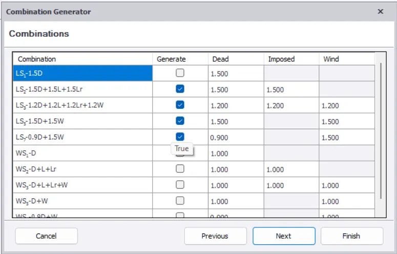
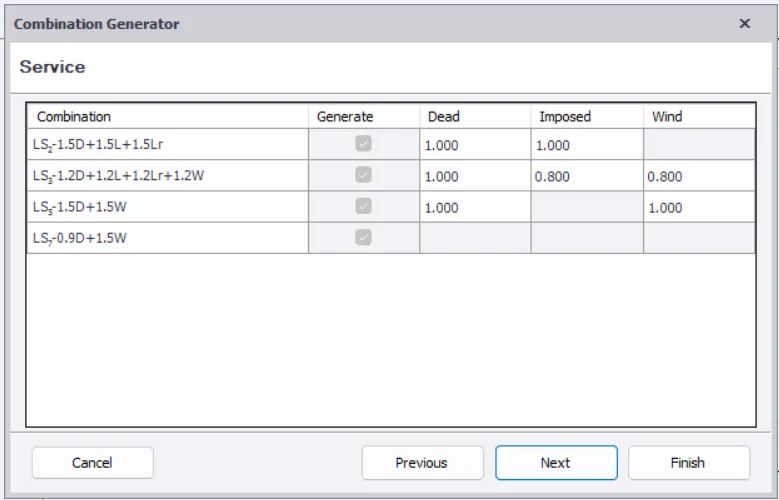
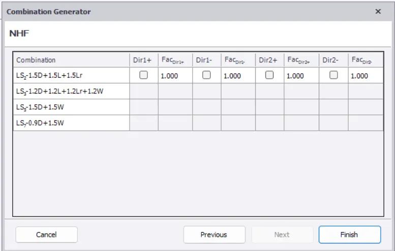
- Below is the generated load combinations:
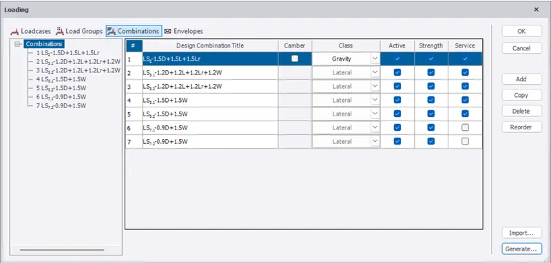
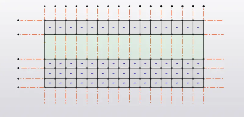
- Now the load cases and the load combinations have been generated so next step is to go to the ground level and apply the dead load as shown below:
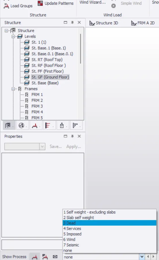
- Now go to the Load cases at the bottom of the screen of the software, there we will be finding an option of load cases just click on that option and select Dead load in that drop-down list just as shown in the below given image:
- After selecting the load cases, go to the Load tab then there will be an option named as the Area in the Panel loads section click that option just as shown in the below given image:

- Now apply the dead load of 1.2kN/sq.m by selecting the slab one-by-one just as shown in the below given image:
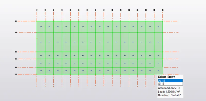
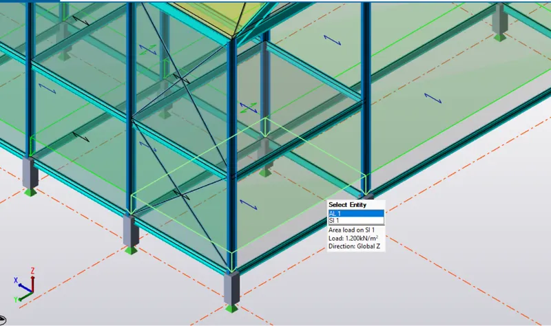
- Similarly apply the floor finish loading on the other floors also as shown below:
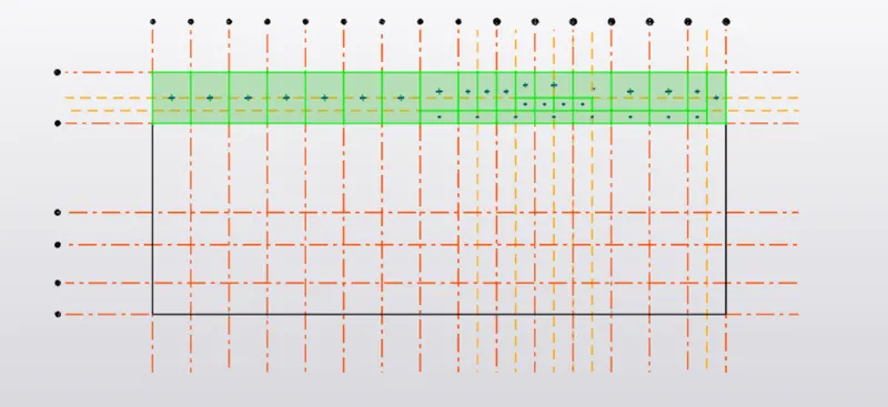
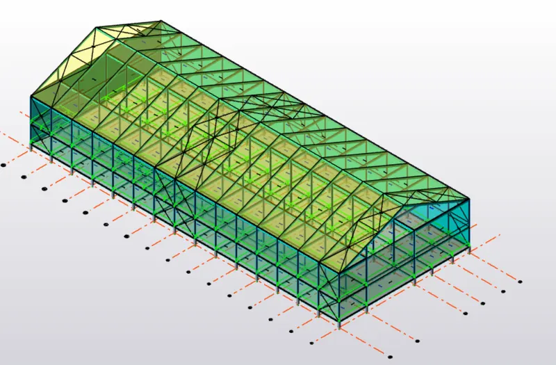
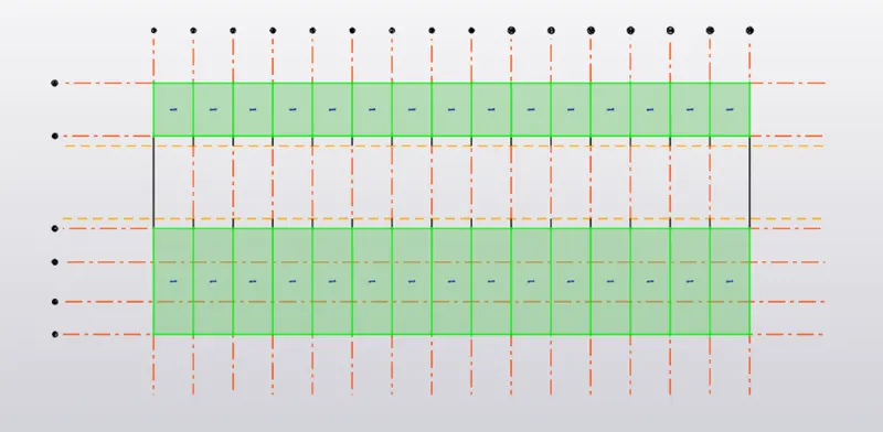
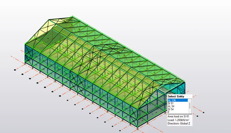
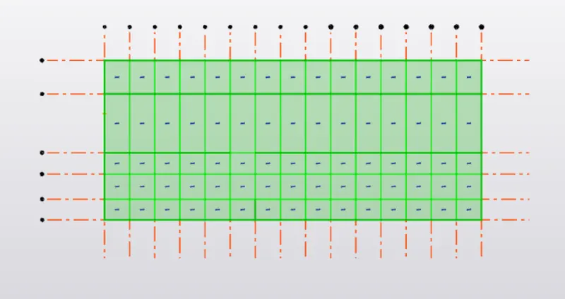
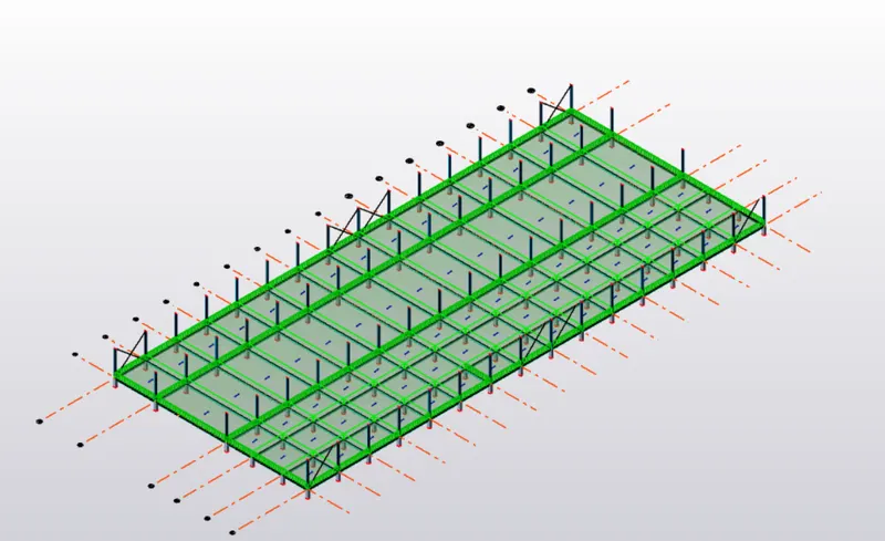
- Now we will be applying the brickwall loading to the structure on the slabs, and in order to apply the brickwall loading go to the load tab there will be an option Full UDL in the panel load section just click on that option just as shown in the below given image:

- Apply the 15kN/m brickwall loading, and apply the loadings as shown below in the given image:
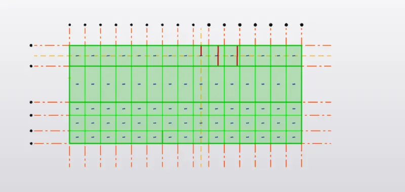
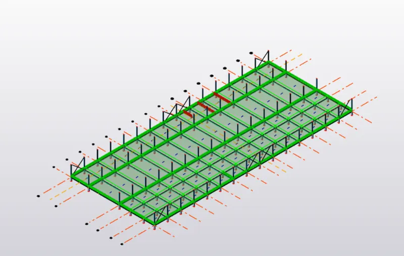
- Now we have to apply the brick loads for the interior bricks, and in order to assign the brick loads in the interior wall just go to the load tab click on that then there will be an option named as the Point Load just click on that option as shown in the below given image:

- Now draw the loads with the help of the line loads just as shown in the below given image:
- Do the same procedure for the other floors just as shown in the below given image:
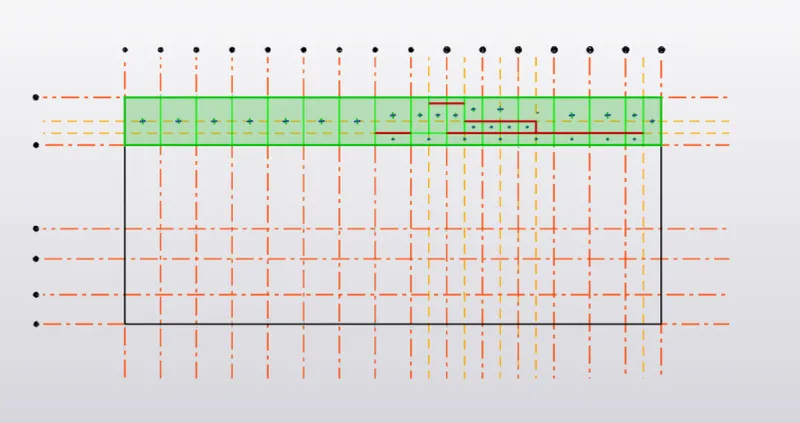
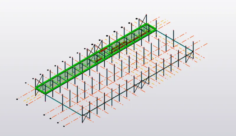
- Now we will be applying on the roof floor of 1.5kN/sq.m loading on the Roof just as shown in the below given image:
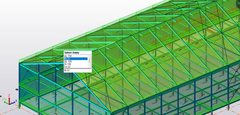
- Now we are done with the dead load calculation and the assignment of the loads on each floor. Next we will be calculating the Imposed load according to the IS code.
Calculations of Imposed Load:
The calculation of the Imposed load is done by using the IS 875-Part 2 as we can see in the below table:
| LIVE LOADS (According to the IS 875: Part 2): | |
| Staircase | 5kN/sq.m |
| Workshop | 5kN/sq.m |
| Common Area | 5kN/sq.m |
| Meeting Room | 3kN/sq.m |
| Equipment Room | 5kN/sq.m |
| Toilet | 2kN/sq.m |
| Store Room | 5kN/sq.m |
| Office Room | 2.5kN/sq.m |
| Conference Room | 3kN/sq.m |
| Canteen | 3kN/sq.m |
| Roof Load | 0.75kN/sq.m |
| Maintainance room | 5kN/sq.m |
- Now apply the live loads into the structure and in order to apply the live loads, go to the Load cases at the bottom of the screen of the software, there we will be finding an option of load cases just click on that option and select Dead load in that drop-down list just as shown in the below given image:
-
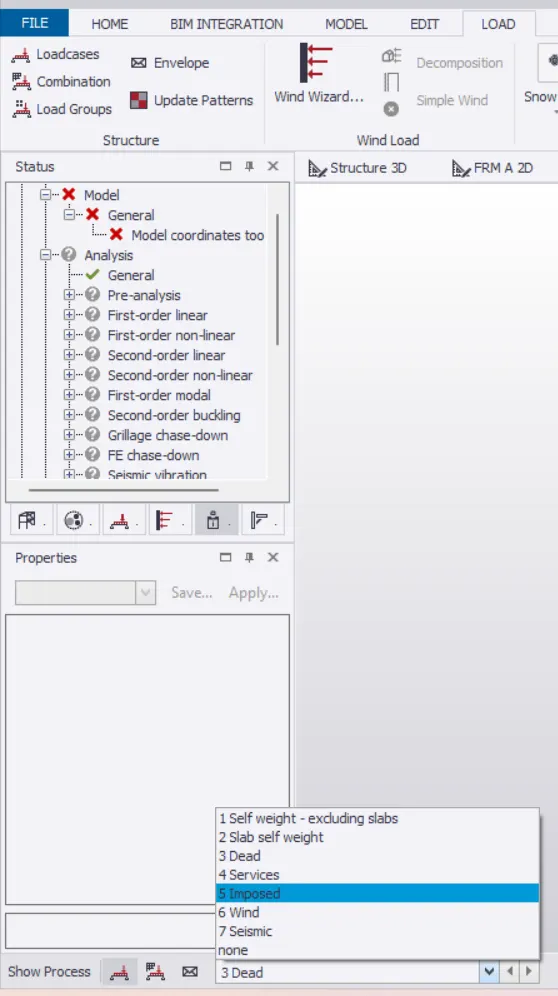
- After selecting the load cases, go to the Load tab then there will be an option named as the Area in the Panel loads section click that option just as shown in the below given image:
-
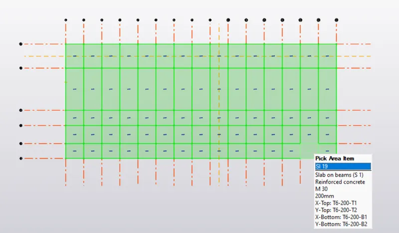
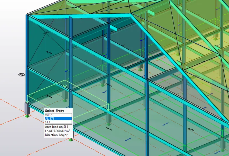
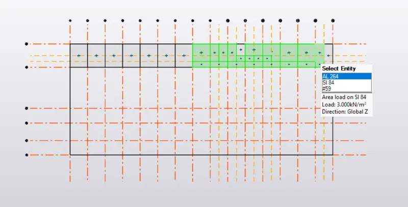
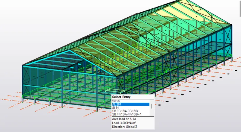
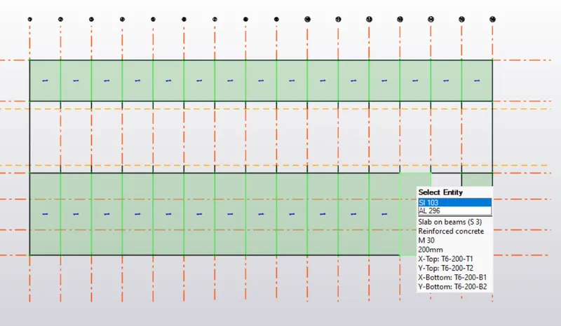
- Now apply the imposed loads according to the plan just as shown in the below given image:
Ground Floor:
First Floor:
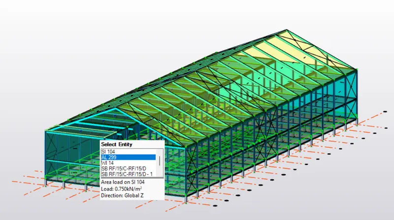
- Now apply the roof loading of 0.75kN/sq.m at the Roof level just as shown in the below given image:
Manual calculation of Crane loading:
Given Data:
Centre-to-centre to wheel distance - 14m.
Weight of Crab - 40kN.
Numbers of wheels on each side - 2 nos.
Total number of Wheels - 4 nos.
Wheel base - 2m.
Weight of crane - 60kN.
Span of the gantry girder (Maximum centre to centre distance between 2 columns) - 6m.
Step 01: Calculation of Maximum Wheel Load:
- There are two loads acting on the crane girder:
- UDL due to self-weight of the crane.
- Concentrated load due to weight of the crab/trolley and crane capacity (Weight lifted by the hook).
1.Calculation for UDL due to Self weight of the crane:
UDL due to the self-weight of the crane = Self weight of the crane/Centre-to-centre distance between the wheels.
UDL due to the self-weight of the crane = 60/14
UDL due to the self-weight of the crane = 4.3kN/m.
2. Calculation of the Concentrated load due to the weight of the crab/trolley and crane capacity:
Concentrated load due to the weight of the crab/trolley and crane capacity = Weight of crab + Crane Capacity.
Concentrated load due to the weight of the crab/trolley and crane capacity = 40 + 100.
Concentrated load due to the weight of the crab/trolley and crane capacity = 140 kN.
Minimum hook approach = 1m
Applying the equilibrium equations,
Ra + Rb = 140 + (4.3* 14) = 200 kN
∑Mb = 0
(14 * Ra) – ( 140 * 13) – ( 4.3 * 14 * 7) = 0
Ra = 160 kN
Rb = 200 – 160 = 40 kN
Static wheel load(Ra) = 160 kN.
This load is shared by 2 wheels , Load transferred by 1 wheel = 160/2 = 80 kN.
Therefore, Adding 25% for Impact = 100 kN.
Factored load = 100 * 1.5 = 150 kN.
Maximum Bending Moment:
Assume self weight of the gantry girder = 1.6 kN/m
Self Weight of the rails = 0.4 kN/m
Total UDL = 1.6 + 0.4 = 2 kN/m
For maximum BM, the wheel loads should be kept so that the C.G of 2 wheel loads and the wheel loads recline equidistant from the centre of the span
i.e Max BM occurs under wheel load ‘a’ when centre of the span is at equal distance from the wheel load and the C.G of the wheel loads:
Ra + Rb = (150 *2) + (2 * 6) = 312 kN.
∑M at B = 0.
(6 * Ra) – (150 * 1.5) – (150 * 3.5) – (2 * 6 * 6/2 ) = 0.
Ra = 131 kN.
Rb = 181 kN.
Max BM at a = (131 * 2.5) – (2 * 2.5^2/2) = 321.25 kNm.
Maximum Shear force in gantry girder:
∑M at B = 0.
(6 * Ra) – ( 150 * 6) –(150 * 4) – (2 * 6^2 / 2) = 0.
Ra = 256 kN.
Lateral force:
Surge load along y = 10 % of (crane capacity + crab load) = 0.1 * (100 + 40 ) = 14 kN.
This load is shared by 4 wheels = 14 / 4 = 3.5 kN.
Finding the BM for this load:
150 -à 321.25 kNm.
3.5 -à ( 3.5 * 321.25) / 150 = 7.5 kNm.
Brake load along x = 5 % of static wheel load = 0.05 * 160 = 8 kN.
- Now we will be applying the crane loads into the structure.
- Now lets apply the crane load in the form of nodal loads on the brackets
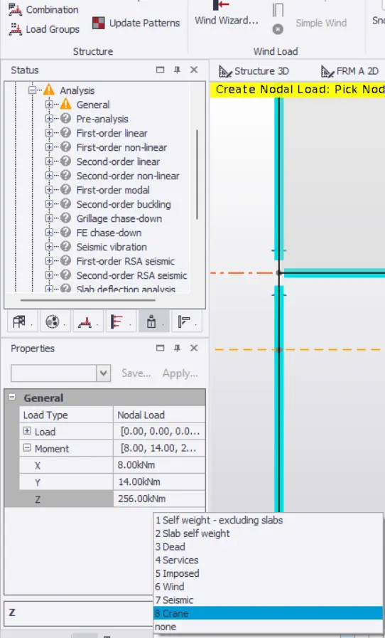
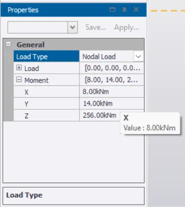
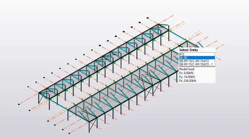
- (Brake, Surge, Max SF) are chosen as (x,y,z) loads repectively and In our case, it is (8 , 14 , 256).
- Now go to the Load tab then there will be an option named as the Loadcases just click on that option just as shown in the below given image:
- Now there will be a new dialouge box named as the dialouge box, in that dialouge box add the case as Crane load just as shown in the below given image:
- After creating the Crane loadcase, now we will be applying it into the structure. And in order to apply the crane loads go to the left bottom of the screen there will be options of selecting the loads just click that after that there will be a drop-down list and in that list there will be an option named as the Crane just click on that just as shown in the below given image:
- Now go to the Load tab click on that tab then there will be a section named as the Member loads and in that section there will be another option named as the Point just click on that option just as shown in the below given image:

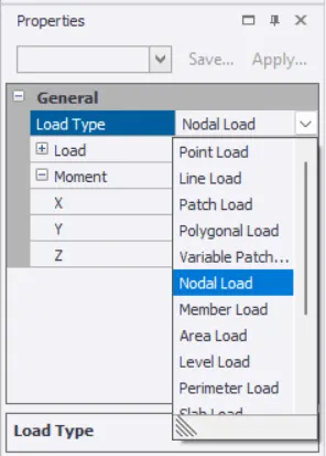
- After selection of the Point loads from the member loads, at the left side of the screen there will be an option named as the Properties section and in that section there will be an option named as the Load from there select Load type as the Nodal load just as shown below:
- After selecting the Load type, choose x,y,z loads repectively and In our case the loads are 8, 14, 256 just as we can see in the below given image:
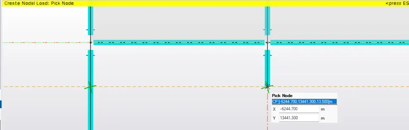
- After this pick the nodes from the brackets just as shown in the below given image:
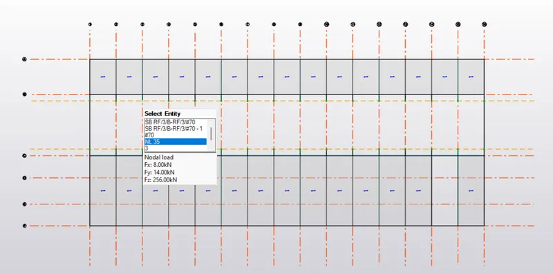
- Below is the result after applying the point loads in 2D and 3D as shown below:
- Now we are done with the application of the crane loads after this we will be calculating the wind loads manually.
Calculation of Wind loads manually:
- To generate the manual wind loading in the design report based IS code according to the given input.
- Basic Wind Speed = 39 m/s.
- Terrain Category = 2.
Manual Calculations:
Given Data:
Basic wind speed, Vb = 39 m/s.
Terrain Category = 2.
Greater horizontal dimensions of structure, l = 90m.
Shorter side dimension, w = 38m.
Eaves level height of the structure, h = 18.31m.
Width of frame-1 between A and B = 6m.
According to the IS 875 Part-lll Clause 6.3.1:
Vb = Basic wind speed = 39 m/s. (According to the IS code 875 Part:2 Appendix:A).
Design Wind Speed, Vz = Vb*k1*k2*k3*k4.
Where,
k1 = Probability Factor.
k2 = Terrain height, structure factor.
k3 = Topography Factor.
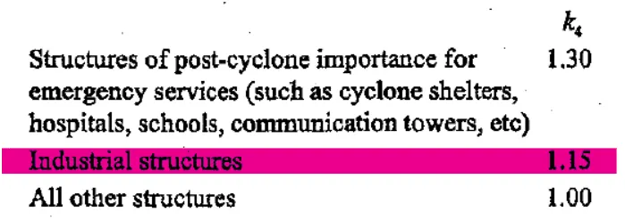
k4 = Importance Factor for the cyclonic region.
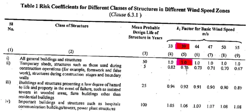
- According to IS 875 Part-lll: Table:1 the value of k1 = 1.0.
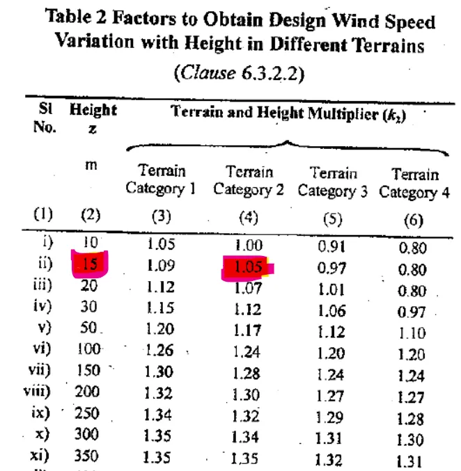
- According to IS 875 Part-lll, Table:2, the value of k2 = 1.06.
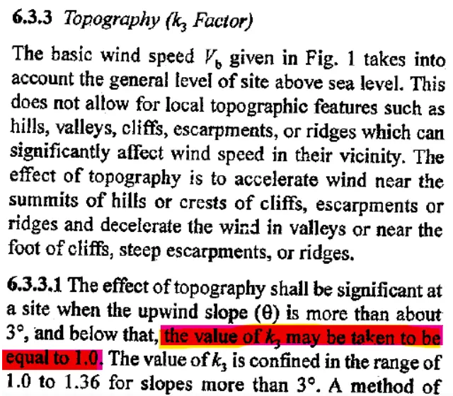
- According to IS 875 Part-lll, the value of k3 = 1.
- According to IS Part-lll, the value of k4 = 1.15.
Calculations:
Wind Speed = 39 m/s.
Life Period of the structure = 50 years.
Terrain Category = 2.
Class Structure = A.
Step 1: Design Wind Speed and Design Wind Pressure:
- Design Wind Speed:
Design Wind Speed, Vz = Vb*k1*k2*k3*k4.
Design Wind Speed, Vz = 39*1.0*1.06*1*1.15.
Design Wind Speed, Vz = 47.54 m/s.
Design Wind Pressure, Pz = 0.6*`Vz^2`
Pz = 0.6*`47.54^2`
Design Wind Pressure, Pz = 1356.1 N/sq.m.
Design Wind Pressure, Pz = 1.35 kN/sq.m.
Roof angle = 25 degree.
Internal pressure co-efficient = 0.50 (Upto 20% opening).
Internal pressure co-efficient = +0.50 (Upto 20% opening).
Step 2 : Ratio of wall and roof co-efficient:
Wall:
l/w = 90/38 = 2.37
h/w = 18.31/38 = 0.48
Roof:
h/w = 0.67.
Wind directions +Y,-Y,+X,-X:
| Wind Load along +Y-direction (Face A): | ||
| Cpi + | Cpi - | |
| l/w =1 | l/w = 1 | |
| External Pressure Co-efficient,Cpe | 0.7 | 0.7 |
| Internal Pressure Co-efficient,Cpi | 0.5 | -0.5 |
| Net-Pressure,Cp = Cpe-Cpi | 0.2 | 1.2 |
| Design wind pressure on the wall,Pz (kN/sq.m) | 1.33 | 1.33 |
| Loading to be applied on the wall, Cp x Pz | 1.463 | 1.596 |
| K2 factor from table 2:1.05 | 1.536 | 1.675 |
| Wind Load along +Y-direction (Face B): | ||
| Cpi + | Cpe - | |
| l/w = 1 | l/w = 1 | |
| External Pressure Co-efficient,Cpe | -0.25 | -0.25 |
| Internal Pressure Co-efficient,Cpi | 0.5 | -0.5 |
| Net-Pressure,Cp = Cpe-Cpi | -0.75 | 0.25 |
| Design wind pressure on the wall,Pz (kN/sq.m) | 1.33 | 1.33 |
| Loading to be applied on the wall, Cp x Pz | -0.99 | 0.33 |
| K2 factor from table 2:1.05 | -1.03 | 0.34 |
| Wind Load along +Y-direction ( Face C and D): | ||
| Cpi + | Cpi - | |
| h/w = 0.67 | h/w = 0.67 | |
| External Pressure Co-efficient,Cpe | -0.6 | -0.6 |
| Internal Pressure Co-efficient,Cpi | 0.5 | -0.5 |
| Net-Pressure,Cp = Cpe-Cpi | -1.1 | -0.1 |
| Design wind pressure on the wall,Pz (kN/sq.m) | 1.33 | 1.33 |
| Loading to be applied on the wall, Cp x Pz | -1.463 | -0.133 |
| K2 factor from table 2:1.05 | -1.53 | -0.14 |
| Wind Load along -Y-direction (Face A): | ||
| Cpi + | Cpi - | |
| l/w = 1 | l/w = 1 | |
| External Pressure Co-efficient,Cpe | -0.3 | -0.3 |
| Internal Pressure Co-efficient,Cpi | 0.5 | -0.5 |
| Net-Pressure,Cp = Cpe-Cpi | -0.7 | 0.2 |
| Design wind pressure on the wall,Pz (kN/sq.m) | 1.33 | 1.33 |
| Loading to be applied on the wall, Cp x Pz | -0.931 | 0.266 |
| K2 factor from table 2:1.05 | -0.977 | 0.279 |
| Wind Load along -Y-direction (Face B): | ||
| Cpi + | Cpi - | |
| l/w =1 | l/w = 1 | |
| External Pressure Co-efficient,Cpe | 0.7 | 0.7 |
| Internal Pressure Co-efficient,Cpi | 0.5 | -0.5 |
| Net-Pressure,Cp = Cpe-Cpi | 0.2 | 1.2 |
| Design wind pressure on the wall,Pz (kN/sq.m) | 1.33 | 1.33 |
| Loading to be applied on the wall, Cp x Pz | 0.266 | 1.596 |
| K2 factor from table 2:1.05 | 0.28 | 1.67 |
| Wind Load along -Y-direction (Face C and D): | ||
| Cpi+ | Cpi- | |
| h/w = 0.67 | h/w = 0.67 | |
| External Pressure Co-efficient,Cpe | -0.7 | -0.7 |
| Internal Pressure Co-efficient,Cpi | 0.5 | -0.5 |
| Net-Pressure,Cp = Cpe-Cpi | -1.2 | -0.2 |
| Design wind pressure on the wall,Pz (kN/sq.m) | 1.33 | 1.33 |
| Loading to be applied on the wall, Cp x Pz | -1.6 | -0.266 |
| K2 factor from table 2:1.05 | -1.68 | -0.28 |
| Wind Load along +Y-direction (Face E and F :0 degree): | ||
| Cpi+ | Cpi- | |
| h/w = 0.67 | h/w = 0.67 | |
| External Pressure Co-efficient,Cpe | -1.03 | -1.03 |
| Internal Pressure Co-efficient,Cpi | 0.5 | -0.5 |
| Net-Pressure,Cp = Cpe-Cpi | -1.53 | -0.53 |
| Design wind pressure on the wall,Pz (kN/sq.m) | 1.33 | 1.33 |
| Loading to be applied on the wall, Cp x Pz | -2.034 | -0.704 |
| K2 factor from table 2:1.05 | -2.13 | -0.74 |
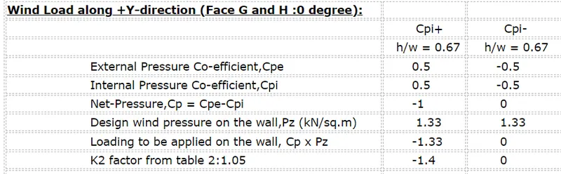
| Wind Load along +Y-direction (Face G and H :0 degree): | ||
| Cpi+ | Cpi- | |
| h/w = 0.67 | h/w = 0.67 | |
| External Pressure Co-efficient,Cpe | 0.5 | -0.5 |
| Internal Pressure Co-efficient,Cpi | 0.5 | -0.5 |
| Net-Pressure,Cp = Cpe-Cpi | -1 | 0 |
| Design wind pressure on the wall,Pz (kN/sq.m) | 1.33 | 1.33 |
| Loading to be applied on the wall, Cp x Pz | -1.33 | 0 |
| K2 factor from table 2:1.05 | -1.4 | 0 |
| Wind Load along +X-direction (Face E and F :90 degree): | ||
| Cpi + | Cpi- | |
| h/w = 0.67 | h/w = 0.67 | |
| External Pressure Co-efficient,Cpe | -0.8 | -0.8 |
| Internal Pressure Co-efficient,Cpi | 0.5 | -0.5 |
| Net-Pressure,Cp = Cpe-Cpi | -0.13 | -0.3 |
| Design wind pressure on the wall,Pz (kN/sq.m) | 1.33 | 1.33 |
| Loading to be applied on the wall, Cp x Pz | -0.173 | -0.4 |
| K2 factor from table 2:1.05 | -0.23 | -0.532 |
| Wind Load along +X-direction (Face G and H :90 degree): | ||
| Cpi + | Cpi - | |
| h/w = 0.67 | h/w = 0.67 | |
| External Pressure Co-efficient,Cpe | -0.612 | -0.612 |
| Internal Pressure Co-efficient,Cpi | 0.5 | -0.5 |
| Net-Pressure,Cp = Cpe-Cpi | -1.112 | -0.112 |
| Design wind pressure on the wall,Pz (kN/sq.m) | 1.33 | 1.33 |
| Loading to be applied on the wall, Cp x Pz | -1.48 | -0.148 |
| K2 factor from table 2:1.05 | -1.554 | 0.1554 |
| Wind Load along -Y-direction (Face G and H :0 degree): | ||
| Cpi+ | Cpi- | |
| h/w = 0.67 | h/w = 0.67 | |
| External Pressure Co-efficient,Cpe | -1.03 | -1.03 |
| Internal Pressure Co-efficient,Cpi | 0.5 | -0.5 |
| Net-Pressure,Cp = Cpe-Cpi | -1.53 | -0.53 |
| Design wind pressure on the wall,Pz (kN/sq.m) | 1.33 | 1.33 |
| Loading to be applied on the wall, Cp x Pz | -2.034 | -0.704 |
| K2 factor from table 2:1.05 | -2.13 | -0.74 |
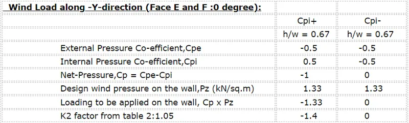
| Wind Load along -Y-direction (Face E and F :0 degree): | ||
| Cpi+ | Cpi- | |
| h/w = 0.67 | h/w = 0.67 | |
| External Pressure Co-efficient,Cpe | -0.5 | -0.5 |
| Internal Pressure Co-efficient,Cpi | 0.5 | -0.5 |
| Net-Pressure,Cp = Cpe-Cpi | -1 | 0 |
| Design wind pressure on the wall,Pz (kN/sq.m) | 1.33 | 1.33 |
| Loading to be applied on the wall, Cp x Pz | -1.33 | 0 |
| K2 factor from table 2:1.05 | -1.4 | 0 |
| Wind Load along -X-direction (Face G andH :90 degree): | ||
| Cpi+ | Cpi- | |
| h/w = 0.67 | h/w = 0.67 | |
| External Pressure Co-efficient,Cpe | -0.8 | -0.8 |
| Internal Pressure Co-efficient,Cpi | 0.5 | -0.5 |
| Net-Pressure,Cp = Cpe-Cpi | -0.13 | -0.3 |
| Design wind pressure on the wall,Pz (kN/sq.m) | 1.33 | 1.33 |
| Loading to be applied on the wall, Cp x Pz | -0.173 | -0.4 |
| K2 factor from table 2:1.05 | -0.23 | -0.532 |
| Wind Load along -X-direction (Face E and F :90 degree): | ||
| Cpi+ | Cpi- | |
| h/w = 0.67 | h/w = 0.67 | |
| External Pressure Co-efficient,Cpe | -0.612 | -0.612 |
| Internal Pressure Co-efficient,Cpi | 0.5 | -0.5 |
| Net-Pressure,Cp = Cpe-Cpi | -1.112 | -0.112 |
| Design wind pressure on the wall,Pz (kN/sq.m) | 1.33 | 1.33 |
| Loading to be applied on the wall, Cp x Pz | -1.48 | -0.148 |
| K2 factor from table 2:1.05 | -1.554 | 0.155 |
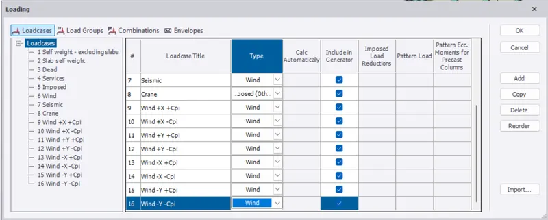
- Now go to load tab then there will be an option named as the Load cases to add the wind load cases just click on that option and add the load cases just as shown in the below given image:
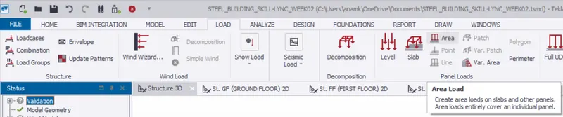
- Now we will be applying the wind loads and to apply the wind loads in the model go to the load ribbons and then in that ribbon there will be an option in the Panel Loads there will be an option called Area just click on that option just as shown in the below given image:
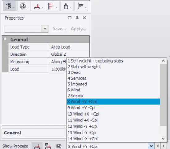
- Now select the frame and select the combination which is present at the bottom of the workspace just as shown in the below given image:
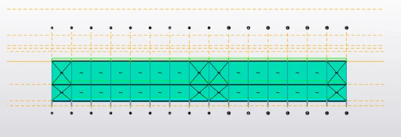
- Wind Load +Y +Cpi (Face A):
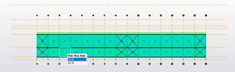
- Wind Load +Y-Cpi (Face A):
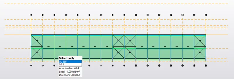
- Wind Load +Y+Cpi (Face B):
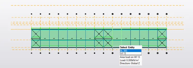
- Wind Load +Y-Cpi (Face B):
- Wind Load +Y+Cpi (Face C):
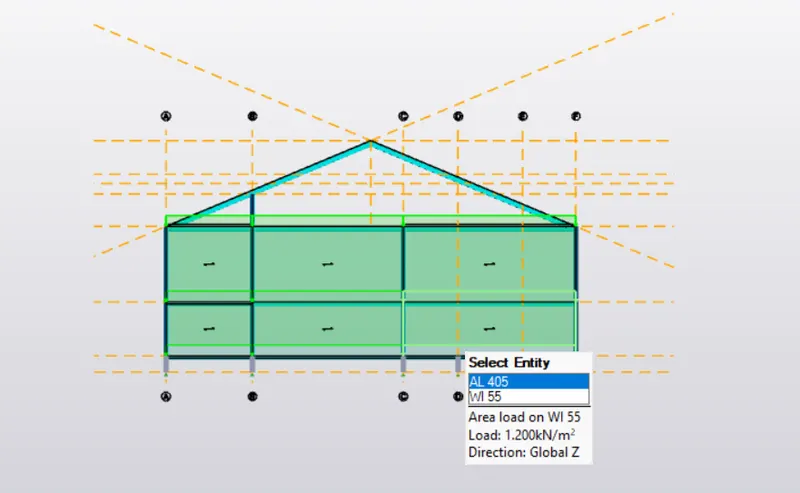
- Wind Load +Y-Cpi (Face C):
- Wind Load +Y+Cpi (Face D):
- Wind Load +Y-Cpi (Face D):
- Wind Load -Y+Cpi (Face A):
- Wind Load -Y-Cpi (Face A):
- Wind Load -Y+Cpi (Face B):
- Wind Load -Y-Cpi (Face B):
- Wind Load -Y+Cpi (Face C):
- Wind Load -Y-Cpi (Face C):
- Wind Load -Y+Cpi (Face D):
- Wind Load -Y-Cpi (Face D):
ROOF LOADS:
- Wind Load +Y+Cpi (Face EF):
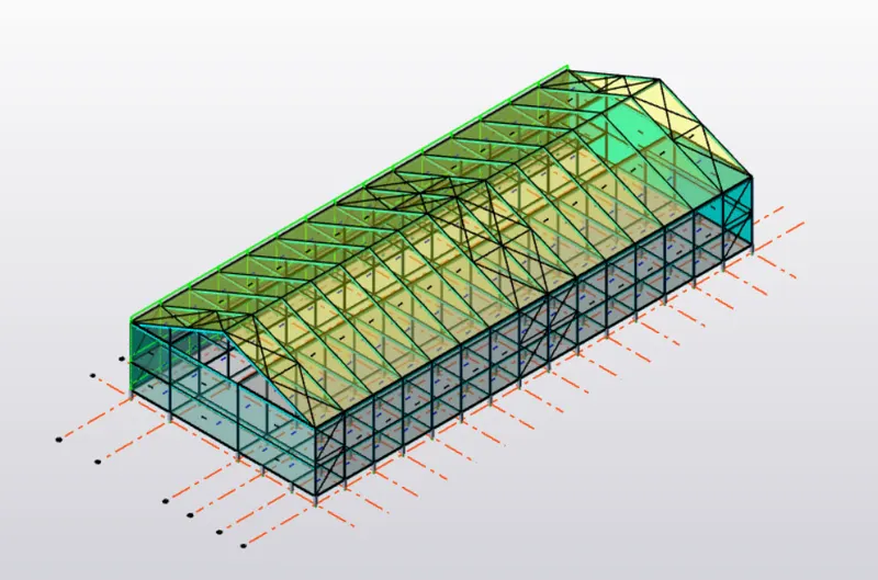
- Wind Load +Y-Cpi (Face EF):
- Wind Load +Y+Cpi (Face GH):
- Wind Load +Y-Cpi (Face GH) has Zero value:
- Wind Load +X+Cpi (Face EF):
- Wind Load +X-Cpi (Face EF):
- Wind Load +X+Cpi (Face GH):
- Wind Load +X-Cpi (Face GH):
- Wind Load -Y+Cpi (Face GH):
- Wind Load -Y-Cpi (Face GH):
- Wind Load -Y+Cpi (Face EF):
- Wind Load -Y-Cpi (Face EF) has zero value:
- Wind Load -X+Cpi (Face GH):
- Wind Load -X-Cpi (Face GH):
- Wind Load -X+Cpi (Face EF):
- Wind Load -X-Cpi (Face EF):
- Now we are done with applying the wind loads,now we will be applying the seismic loads.
Seismic Loads:
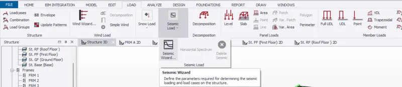
- In order to assign the seismic load first go to the Load tab click on that tab then there will be an option named as the Seismic Wizard in that tab just click on that option just as shown in the below given image:
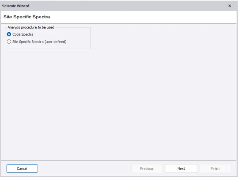
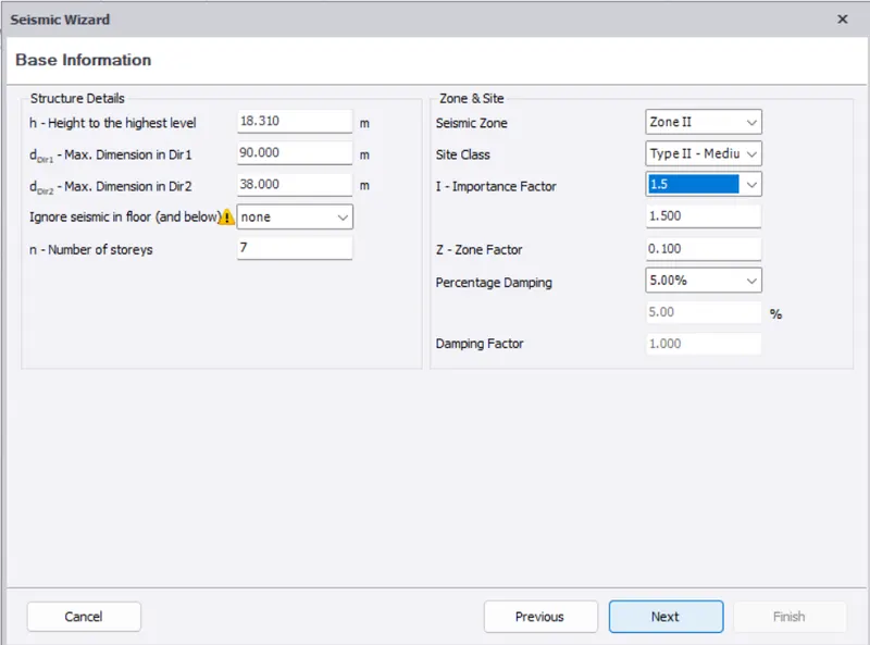
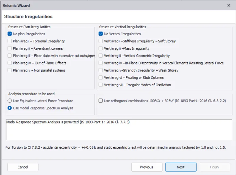
- After that there will be another dialouge box named as the Seismic Wizard and follow the steps just as shown in the below given image:
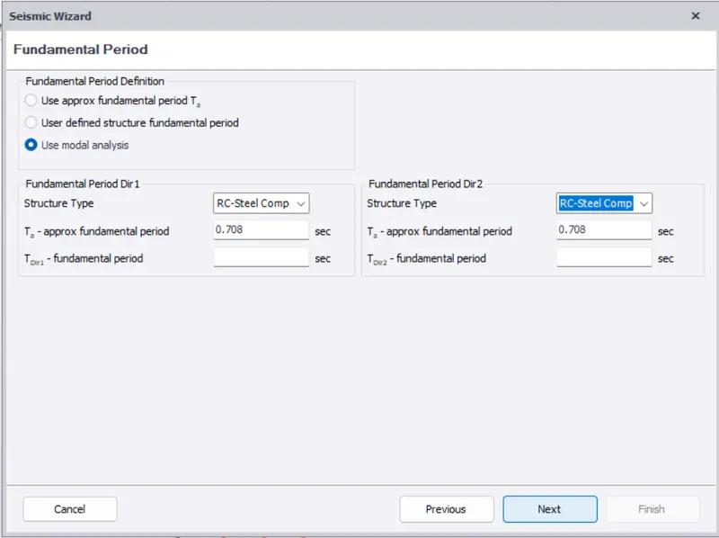
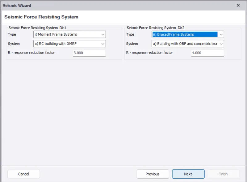
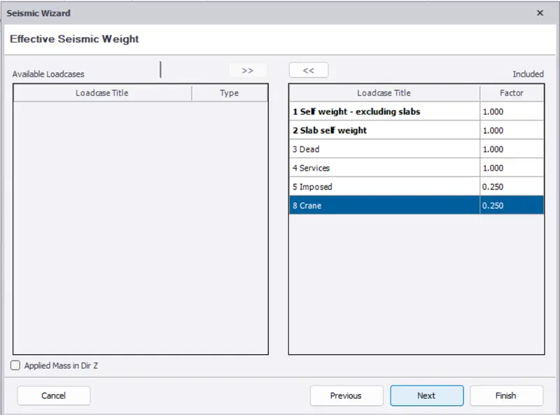
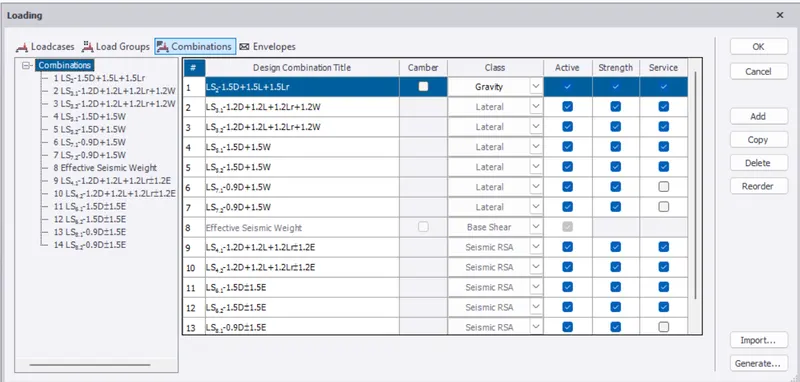
- Now we can see that the combinations have been created just as shown in the below given image:
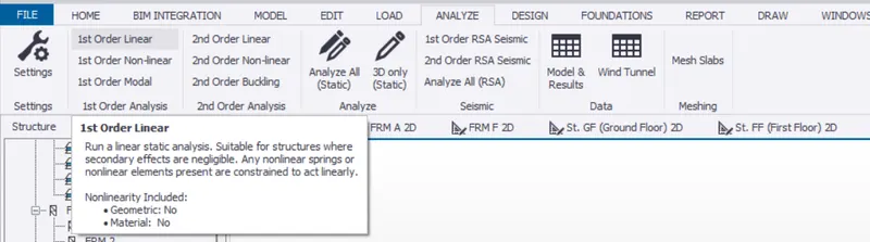
- Now we will validate and we have to run the analyse in our next step
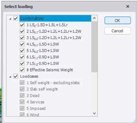
- Then there will be another dialouge box named as the Select loading just click on that option after that check the options just as shown in the below given image and then click OK:
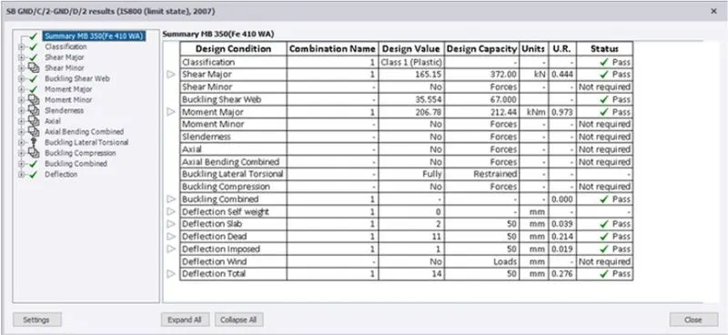
- After this we can check the analysis, and see whether all the components was OK. If not then, adjust or resize the member whenever error occurred as we can see below:
- As the result the Analyze and design a steel building to 10T CRANE as per IS standard code in TEKLA STRUCTURAL DESIGNER is completed sucessfully.And we have sucessfully provided the bracings and moment connection for lateral stability.