Project 1
Hybrid Drives Development:
Data:
%Skill-Lync -> Hybrid Drives Development
% Project 1 - Conventional Vehicle Model
% Description:
%% Initialization File
% Initialization file for loading the variables for the Conventional vehicle simulation model
%% Vehicle Parameters
M = 1500; % Vehicle weight [kg]
Cr = 0.015; % Rolling resistance coefficient
Rw = 0.35; % Rolling radius [m]
Cd = 0.33; % Drag coefficient
Af = 2; % Frontal area [m2]
rhoa = 1.225; % Air density [kg/m3]
Vwind = 0; % Wind velocity [kmph]
g = 9.81; % Gravitational acceleration [m/s2]
theta = 0; % Slope [deg]
myu_road_tire = 1; % Coefficient of friction between tire - road interface
%% Powertrain Parameters
FDR = 3.73; % Final Drive Ratio / Diff Ratio
DiffEff = 0.99; % Differential efficiency (assumed independent of operating conditions)
NumGear = 4; % Number of gears in transmission
TransGear = [1:NumGear]; % Transmission Gears
TransRatio = [3.06, 1.62, 1, 0.7]; % Corresponding Transmission ratios
TransEff = 0.90; % Transmission efficiency (assumed independent of operating conditions)
TC_SR = [0, .5, .6, .7, .8, .87, .92, .94, .96, .97, 1]; % Torque Converter Speed Ratio (Matlab default) -> TurbSpd/PumpSpd
TC_TR = [2.232, 1.5462, 1.4058, 1.2746, 1.1528, 1.0732, 1.0192, 1, 1, 1, 1]; % Torque Converter Torque Ratio (Matlab default) -> TurbTrq/PumpTrq
TC_Cf = 1e-4 * [.72558, .66322, .63463, .59042, .51331, .4144, .29287, .22444, .12186, .04386, 0]; % Torque Converter Capacity Factor (Matlab default) -> PumpTrq/PumpSpd^2 [Nm/rpm^2]
load Vehicle_Data/Engine_data_1_9L_Saturn_95kW
load Vehicle_Data/Trans_Shift_map
%% Driver Parameters
Kp = 10; % P gain for driver PI model
Ki = 1; % I gain for driver PI model
Drive_Cycle_Select = 1; % Drive cycle selection
% Drive cycle values in m/s
if Drive_Cycle_Select == 1
load DriveCycles/UDDS;
elseif Drive_Cycle_Select == 2
load DriveCycles/HWFET;
elseif Drive_Cycle_Select == 3
load DriveCycles/FTP;
elseif Drive_Cycle_Select == 4
load DriveCycles/US06;
elseif Drive_Cycle_Select == 5
load DriveCycles/NEDC;
elseif Drive_Cycle_Select == 6
load DriveCycles/WLTP;
end
time_end = cyc_time(end);
vel_end = cyc_vel(end);
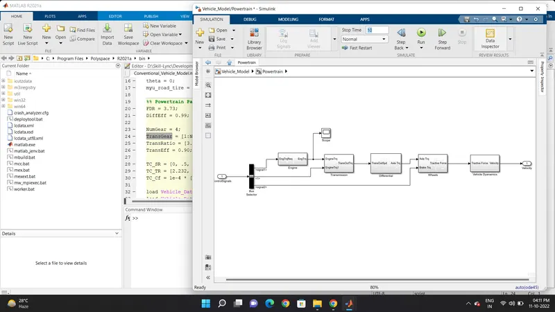
Vehicle Model:
Vehicle Dyanamics:
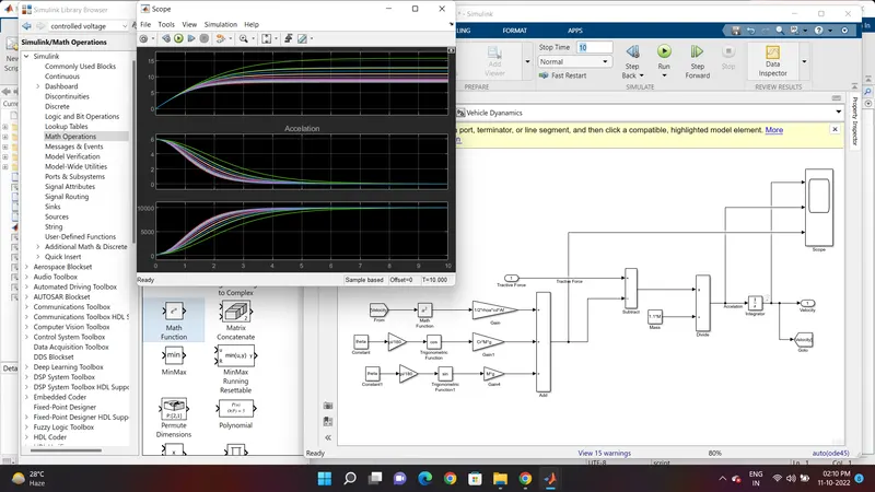
Graph created :
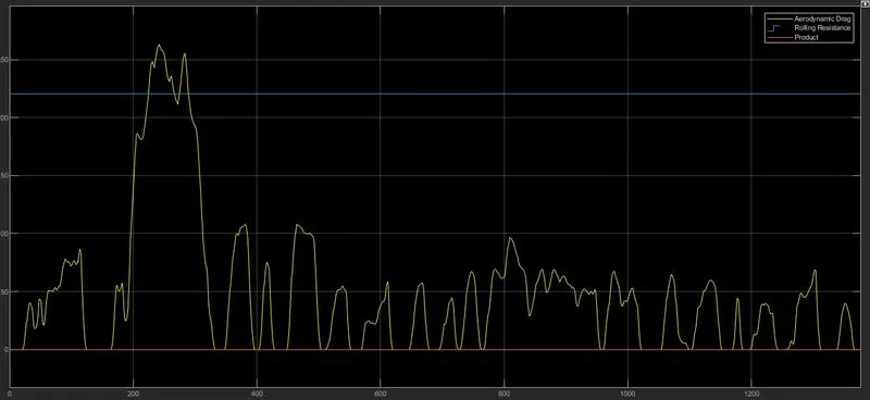
1] Road load
2] Acceleration
3] Tractive force
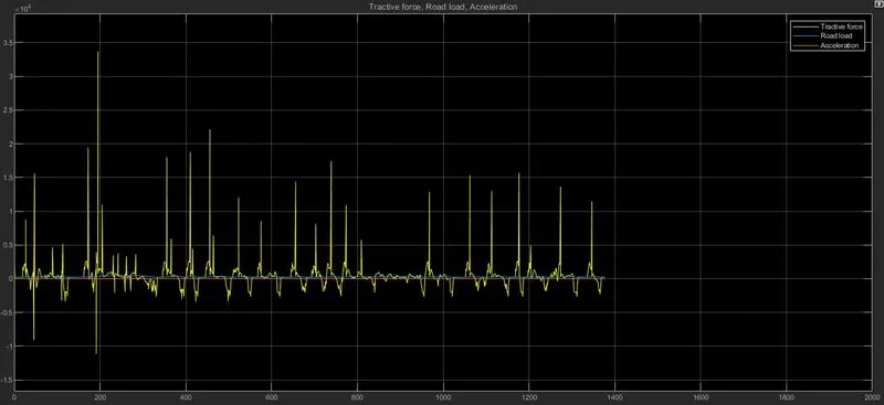
Road load
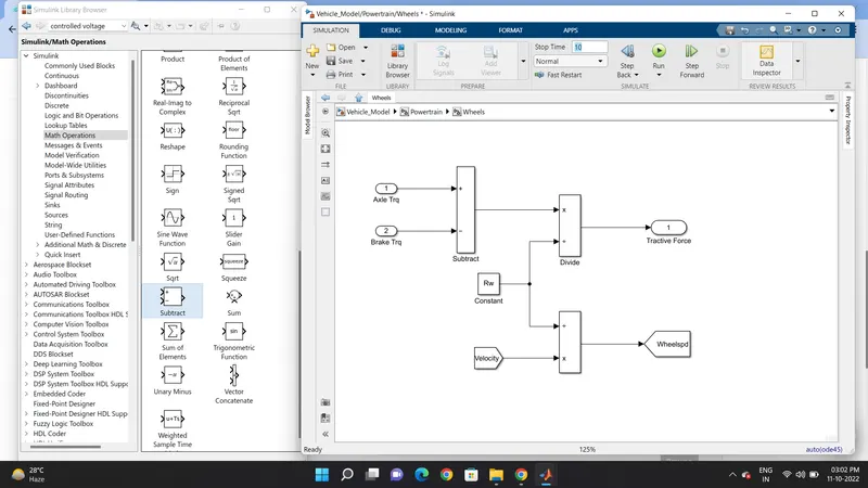
Wheels:
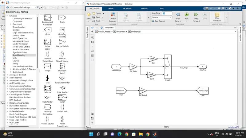
Differential:
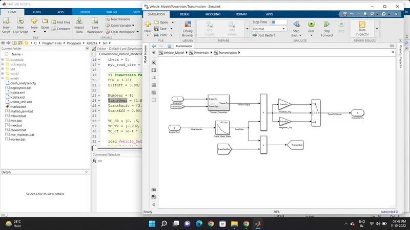
Transmission:
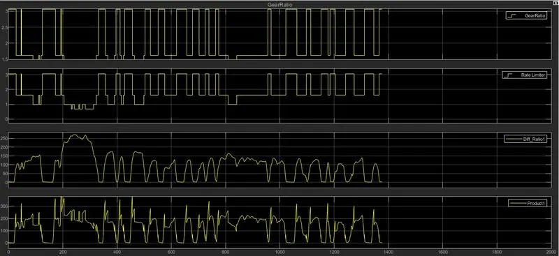
Graph created :
1] Transmission in speed
2] Gear ratio
3] Differential Ratio
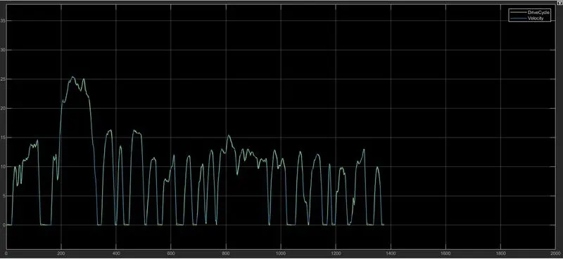
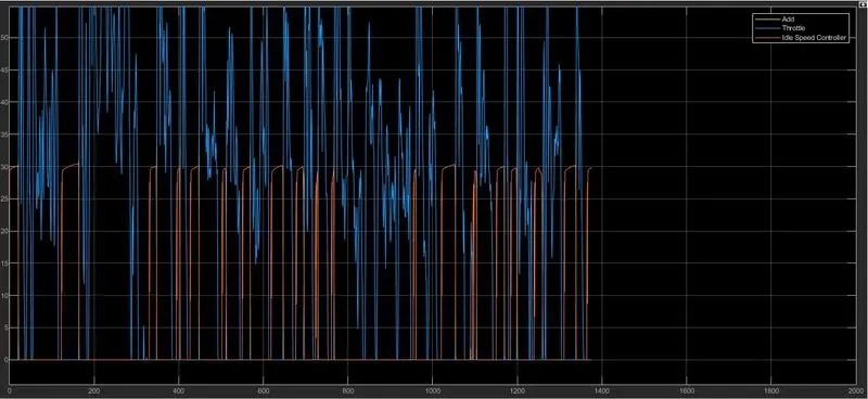
Graph created from Driver Model:
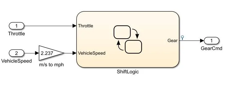
Transmission Control Unit :
Engine :
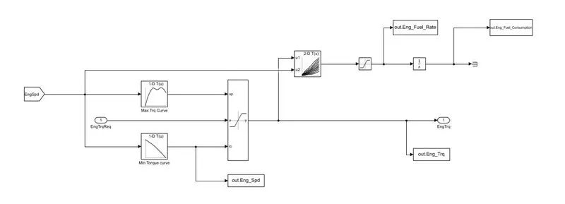
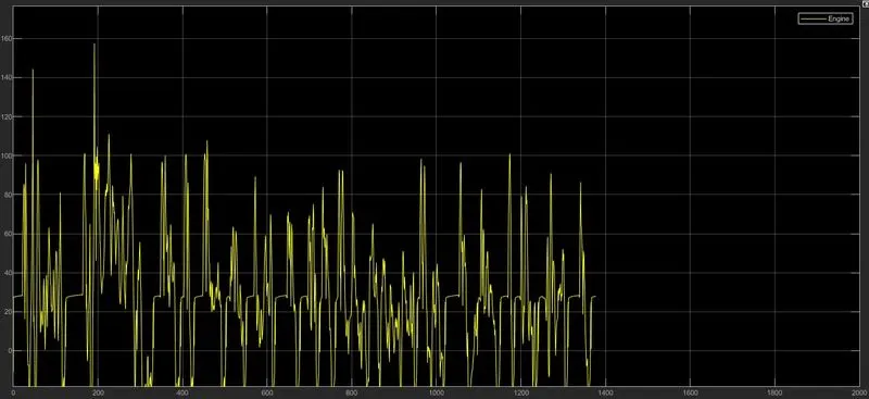
Graph created Engine Torque :
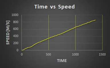
The Compute Fuel economy numbers using UDDS and HWFET cycle:-
1] UDDS Drive cycle
1] Time VS Speed:- In this the speed is increasing continuously.
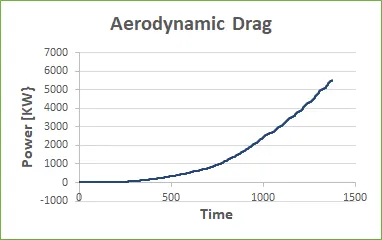
2] Aerodyanamic drag:- Drag as increase when the power increase.
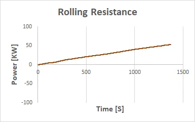
3] Rolling Resistance:- Its also increase when power is increase wrt time.
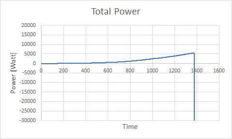
4] Total power = aerodynamic drag+rolling resistance+inertial resistance
Conclusion:-
Total Power is increase slowly as increasing rolling resistance, aerodynamic drag and inertial resistance.
2] HWFET Drive Cycle:-
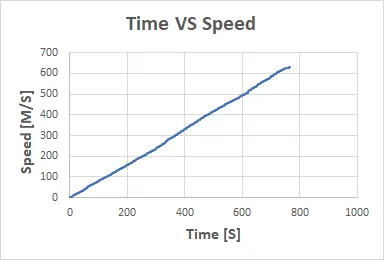
1] Time VS Speed:- Speed is continuosly increase wrt time.
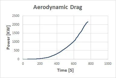
2] Aerodynamic Drag:- Drag as increase when the power increase.
3] Rolling Resistance:- In this resistance is decrease wrt time.
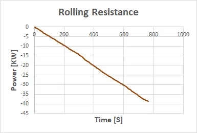
4] Total Power:- aerodynamic drag+rolling resistance+inertial resistance
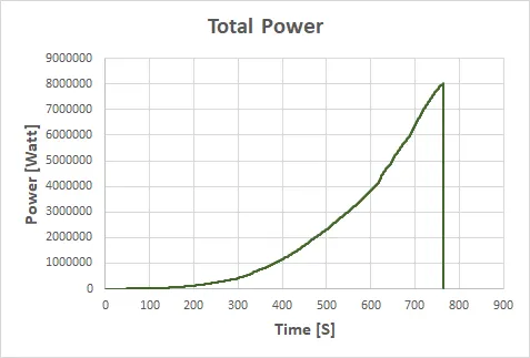
Conclusion:-
Total Power is increase slowly as increasing aerodynamic drag and inertial resistance. but in this drive cycle bad impact occurs due to decreasing rolling resistance.
Result:-
As comparing both cycles we used to UDDS drive cycle. Its best for asses of fuel consumption and Pollutants emission of vehicle in a normalised way.
Code Of Vehicle Model
Project 1 : Conventional Vehicle Model
%% Post-Processing File
% File for post-processing the Conventional vehicle simulation model data
%% Renaming variables
Time = out.tout;
Acc_Pdl = out.Acc_Pdl; % Accelerator pedal [%]
Brk_Pdl = out.Brk_Pdl; % Brake pedal [%]
Gear_Cmd = out.Gear_Cmd; % Transmission gear
Trans_In_Spd = out.Trans_In_Spd*30/pi; % Transmission input speed [rpm]
Trans_Out_Spd = out.Trans_Out_Spd*30/pi;% Transmission output speed [rpm]
Eng_Trq = out.Eng_Trq; % Engine brake torque [Nm]
Eng_Spd = out.Eng_Spd*30/pi; % Engine speed [rpm]
Eng_Fuel_Consump = out.Eng_Fuel_Consumption; % Engine fuel consumption [g]
Veh_Dist = out.Veh_Dist/1000; % Distance traveled by vehicle [km]
Veh_Spd = out.Veh_Spd*18/5; % Vehicle speed [kmph]
Eng_Speed = Eng_Spd*30/pi;
Veh_Distance = Veh_Dist/1000;
Veh_Speed = Veh_Spd*18/5;
Eng_Spd=0.1;
Eng_Trq=10;
%% Data Analysis
Eng_Pwr = Eng_Spd*pi/30*Eng_Trq/1000; % Engine brake power [kW]
rho_petrol = 0.7197; % Density of petrol [kg/L]
kmpl = Veh_Dist(end)/(Eng_Fuel_Consump(end)/1000/rho_petrol); % Fuel economy [kmpl]
%% Plotting vehicle characteristics time trace
figure()
subplot(3,1,1)
hold on
grid on
plot(Time, Acc_Pdl, 'linewidth', 1, 'Color', 'black');
plot(Time, Brk_Pdl, 'linewidth', 1, 'Color', 'red');
ylabel('Pedal [%]')
xlim([0, Time(end)]);
legend('Accel','Brake');
subplot(3,1,2)
hold on
grid on
plot(Time, Trans_In_Spd, 'linewidth', 1, 'Color', 'black');
plot(Time, Trans_Out_Spd, 'linewidth', 1, 'Color', 'red');
ylabel('Speed [rpm]')
xlim([0, Time(end)]);
ylim([0, 6000]);
legend('Trans Input','Trans Output');
subplot(3,1,3)
hold on
grid on
plot(Time, Gear_Cmd, 'linewidth', 1, 'Color', 'black');
xlim([0, Time(end)]);
xlabel('Time [s]');
ylabel('Gear');
%% Plotting engine operating points on engine fuel map
figure('Name','Engine Operating Points');
hold on
grid on
title('Engine Operating Points','fontsize',12);
p1=plot(Eng_map_spd*30/pi,Eng_max_trq,'linewidth',2,'color','r');
p2=line([Eng_map_spd(end)*30/pi Eng_map_spd(end)*30/pi],[0 Eng_max_trq(end)]);
set(p2,'linewidth',1,'linestyle','--','color','k');
p3=line([Eng_map_spd(1)*30/pi Eng_map_spd(1)*30/pi],[0 Eng_max_trq(1)]);
set(p3,'linewidth',1,'linestyle','--','color','k');
[c,h] = contour(Eng_map_spd'*30/pi,Eng_map_trq,Eng_fuel_map');
clabel(c,h);
xlabel('Engine Speed [rpm]');
ylabel('Engine Torque [Nm]');
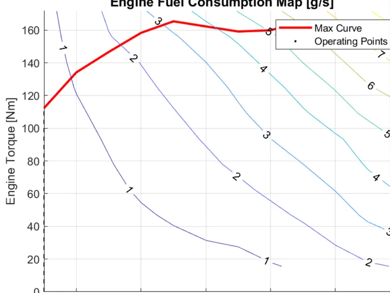
title('Engine Fuel Consumption Map [g/s]');
p4 = plot(Eng_Spd,Eng_Trq,'.','color','k');
legend([p1 p4],{'Max Curve','Operating Points'});
axis([Eng_map_spd(1)*30/pi Eng_map_spd(end)*30/pi 0 Eng_map_trq(end)]);
Fuel economy number (kmpl) is found out from that program using formula
Engine, transmission input, transmission output, and wheel speed are plotted on one graph with respect to the time
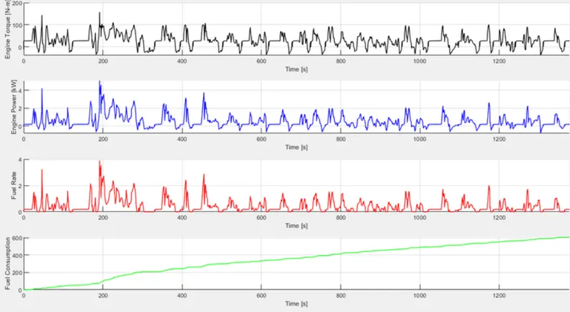
Engine torque, engine power, fuel rate, and fuel consumption are plotted wrt the time using subplots
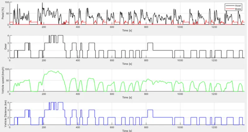
Accelerator and brake pedal, gear command, vehicle speed, and vehicle distance are plotted wrt the time using subplots
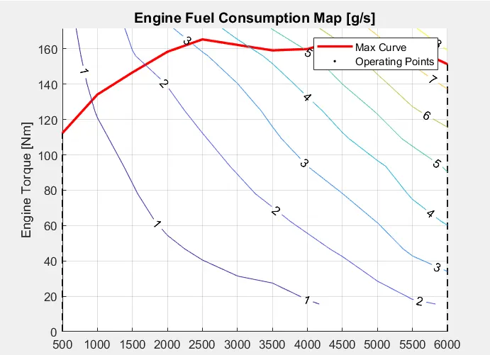
The engine operating points are plotted on the engine fuel map
A similar procedure is followed by changing the drive cycle to 2 i.e. HWFET
Results:
Fuel economy numbers:
As we see, the fuel economy is high in HWFET compared to UDDS, it is because, in urban driving, the vehicle encounters more
traffic and it has to stop for fewer distances and it consumes more fuel at the starting. In HWFET, the vehicle encounters no
traffic and it moves without use of too much braking, so it will have more fuel economy number
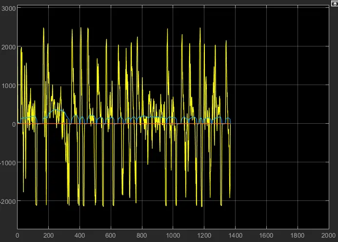
Engine, transmission input, transmission output and wheel speed plot
UDDS drive cycle:
HWFET drive cycle:
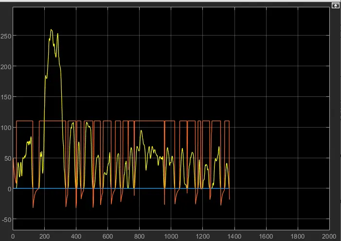
The graph has more fluctuations in UDDS compared to the HWFET cycle because UDDS has more starts and
stops but HWFET does not have too many starts and stops
Braking is high in UDDS when compared to HWFET due to traffic
Peak engine power reached in UDDS is nearly 4800 RPM and that in HWFET is 3800 RPM at the start, because, in UDDS, the vehicle requires more power to start from the initial condition.
Engine torque, engine power, fuel rate, and fuel consumption plot:
UDDS drive cycle:
HWFET drive cycle:
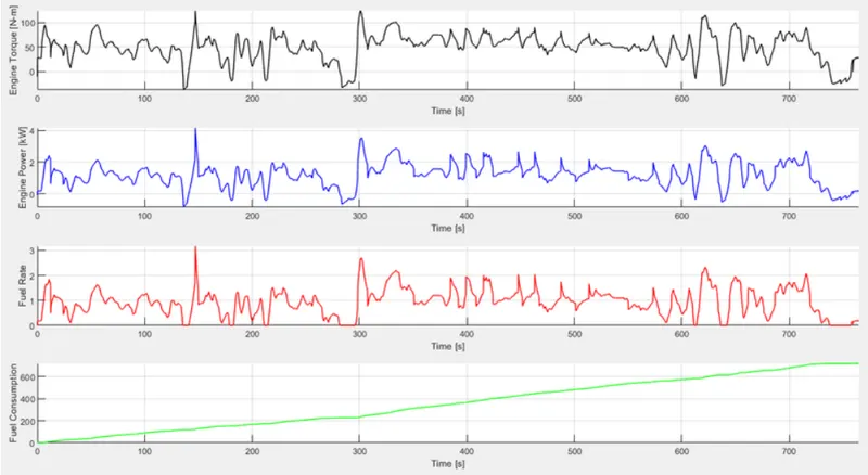
Vehicle consumed more power in the UDDS compared to HWFET cycle because it has too many starts and stops compared to
HWFET. When starting from the initial condition vehicle requires more power
Engine torque is also high in UDDS because while starting from rest, the vehicle requires more torque to overcome the static
friction
The fuel rate is high in HWFET because the vehicle will be in continuous movement, it consumes more fuel
But, fuel economy will be high in HWFET compared to UDDS because there are many stops and starts in UDDS and more fuel is consumed when the vehicle is in an idle position
Accelerator and brake pedal, gear command, vehicle speed, vehicle distance plot
UDDS drive cycle:
HWFET drive cycle:
The accelerator and the brake pedal have more fluctuations because of frequent starts and stops. But in HWFET, the
brake pedal fluctuations are almost near to the zero line as there will be no frequent stops
UDDS cycle mostly runs on 1st, 2nd gears, and uses 3rd, 4th gears very rarely as it does not achieve high speeds in that traffic. In the HWFET cycle, the vehicle mostly runs on 3rd, 4th gears as it will be moving at high speeds. It uses 1st, 2nd gears very frequently when braking is required
Obviously, the vehicle speeds will be high in HWFET compared to UDDS. UDDS also has more fluctuations in the speed due to
frequent braking
The distance travelled in the given time will be high in HWFET than UDDS because of the traffic barrier in UDDS
Engine operating points on the engine fuel map
UDDS drive cycle:
HWFET drive cycle: