Pre-processing of dashboard of a car for NVH in ANSA
Objective:
The objective of this project is to perform FEA preprocessing for the dashboard (plastic component with varying thickness) of a car. Under preprocessing, geometry cleanup, midsurface extraction, and 2D shell meshing need to be done with all the features in the model captured properly and with good mesh flow. All the mesh elements need to follow the quality criteria based on NVH given below,
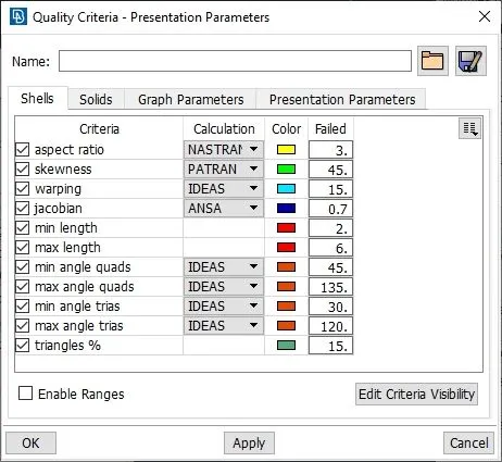
| S.no. | Quality Criteria | Value |
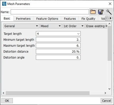
| 1 | Target/Average length | 4 |
| 2 | Minimum length | 2 |
| 3 | Maximum length | 6 |
| 4 | Aspect | 3 |
| 5 | Warpage | 15 |
| 6 | Skewness | 45 |
| 7 | jacobian |
0.7 |
| 8 | Minimum quad angle | 45 |
| 9 | Maximum quad angle | 135 |
| 10 | Minimum tria angle | 30 |
| 11 | Maximum tria angle | 120 |
| 12 | Tria % | 15 |
For preprocessing ANSA preprocessor will be used.
Introduction:
A dashboard (instrument panel (IP)) is a control panel usually located directly ahead of a vehicle's driver, displaying instrumentation and controls for the vehicle's operation. Automotive dashboards are plastic molded components. Here, we are going to prepare an FEA model of the dashboard component of a car for NVH analysis.
FEA
Finite element analysis (FEA) is a numerical method for solving physical engineering problems. The basis of FEA is to make calculations at only a limited number of points (nodes) and then interpolate the results for the entire domain (surface or volume). Any continuous object has infinite degrees of freedom and it's just not possible to solve the problem in this format. The finite element method reduces degrees of freedoms from infinite to finite with the help of discretization, i.e., meshing (nodes & elements). Therefore, meshing is nothing but discretization of a continuous system with an infinite degree of freedoms to a finite degree of freedoms.
Types of mesh
There are three types of meshing done for any model,
- 1-D: 1-D meshing is done for components where one dimension is very large in comparison to the other two dimensions. The area of cross-section is given as a parameter to the mesh elements to capture the original geometry properly. This is done with line-shaped elements like rod, bar, beam, etc. Practical applications of 1-D meshing are long shafts, beams, etc.
- 2-D: 2-D meshing is done for components where two dimensions are very large in comparison to the third dimension (thickness). The thickness is given as a parameter to the mesh elements to capture the original geometry properly. 2-D meshing is done with 2-D elements like quads and trias. Practical applications of 2-D meshing are sheet metal components, plastic components, etc.
- 3-D: 3-D meshing is preferred for components where all the three dimensions are comparable to each other. Mesh elements used for 3-D meshing include tetra, penta, hex, and pyramid. Practical applications of 3-D meshing are transmission casing, crankshaft, etc.
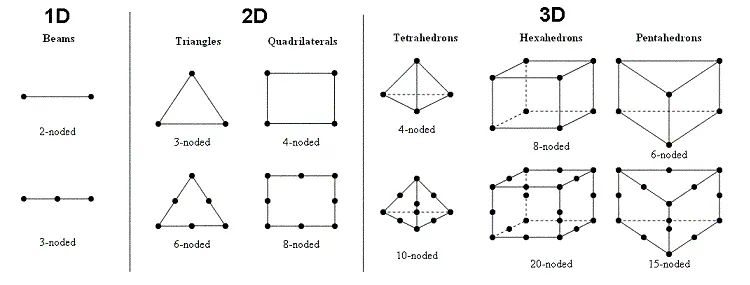
Meshing for dashboard
The dashboard of a car is a plastic component whose thickness is very less compared to the other two dimensions. And for such thin components, 2-D shell mesh is preferred. By doing so, we save a considerable amount of computational time in analysis and still get similar accurate results as from 3D mesh. 2-D shell mesh is generated by extracting the midsurface of the component and assigning thickness to it so as to capture the original geometry. And, then the mesh is generated for the extracted midsurfaces.
Also, here we are considering that the mesh model would be used for NVH analysis. Therefore, absolutely no rotating quads are allowed. And trias also needs to be avoided as much as possible.
Procedure:
First, the dashboard model is imported into the ANSA workspace. The image below shows the given dashboard model,
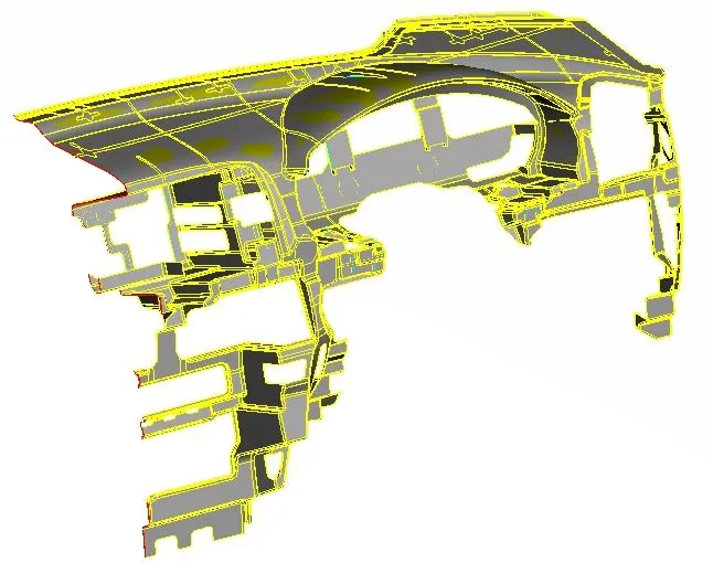
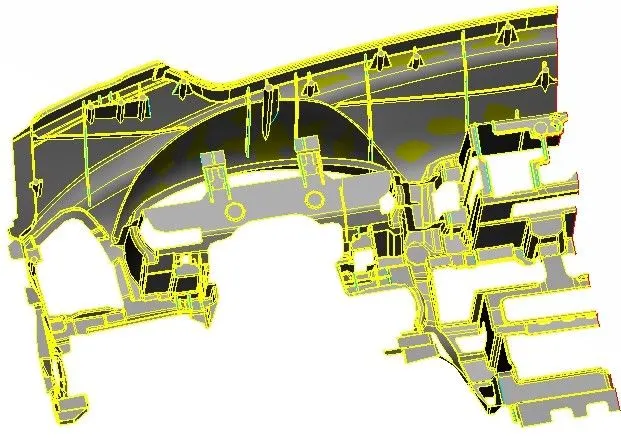
The given model is a half dashboard model. Now, let's look at the preprocessing process for this component. The overall preprocessing process is as follows,
- Analyze and understand the geometry properly
- Perform geometry cleanup
- Extract midsurface and assign new property IDs (PID)
- Perform geometry cleanup for midsurface
- Configure mesh and quality parameters
- Make the surface ready for meshing by defeaturing areas where elements would fail.
- Generate mesh
- Improve mesh flow and quality
The first step after importing the model is to properly analyze and understand the geometry. When a CAD model is imported into the ANSA, there might be several geometrical errors like missing/distorted surfaces, intersecting surfaces, etc. due to the format conversion process or inherent bad model. And, it is important to clear all these errors.
To ensure that all the surfaces are connected properly Faces>Topo tool is used for all the edges of the component. Next, geometry check is performed by going to Checks>Geometry. The image below shows the errors detected.
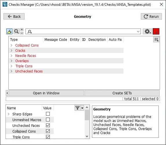
Most of the errors were fixed automatically by right-clicking>fix. Some errors were removed manually. In the end, four unchecked surfaces still remained. But considering the geometry is very complex, and midsurfacing would be done manually, therefore, we can avoid these errors. Next, the orientation of all the faces is modified by going to Faces>Orient. This ensures that all faces are oriented similarly.
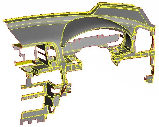
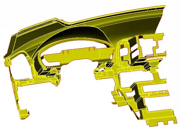
The next, step is to extract the midsurfaces for the component and keep them in separate property id according to the thickness. Midsurfaces are extracted using the manual method i.e. offsetting the surfaces of either face to the middle. The dashboard is a plastic component, which has different features on either side of its face. it can be viewed as a base surface with features like ribs, dog houses, etc. on one side. So, first, the base midsurface is extracted for the dashboard model. First, the thickness is measured at different places using the Measure tool from Utilities>Measure. The dashboard base has a constant thickness of 0.6mm. Therefore, the outer face of the dashboard base is offset to the middle by half of the thickness, i.e., 0.3mm. This is done by going to Topo>Faces>Offset>Faces and all the surfaces on the outer face are selected and the offset value is configured to 0.3mm. Now, the property is assigned to the extracted midsurface by going to Faces>Set PID, and a new property id is created by going to New>PSHELL , and thickness is set to 0.6mm. The image below shows the midsurface extracted.
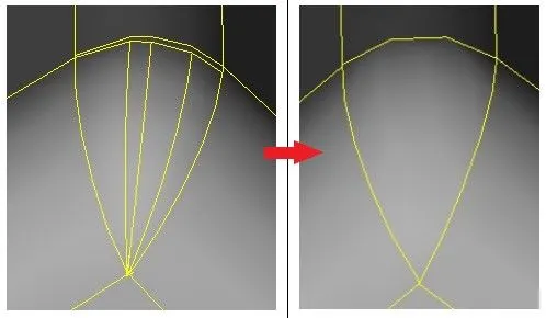
Again, the extracted midsurfaces are checked for geometric errors and fixed. There were some geometrical issues as shown below. To remove this issue, all surfaces in that vicinity are deleted and a new surface is created by going to Faces>New>Fitted or COONS.
The next step is to extract midsurfaces for the ribs and dog houses. Midsurfaces for the ribs can be extracted by the offset tool or the middle tool. The benefit of the 'middle' tool is that it automatically generates a middle surface and assigns a new PID with thickness. And, if the rib is of varying thickness, it assigns an average value. The extracted midsurface of the rib is then connected to the base surface by extending it to the base surface using the Topo>Faces>Extend tool.
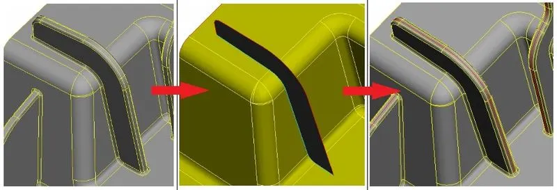
Because of the method of midsurface extraction, sometimes extracted midsurfaces were not connected to each other and also needed geometry cleanup to delete or extend the surface accordingly. For this purpose, the Faces>Intersect & Faces>Extend tool is used.
Next, the dog houses are captured as a cross. After applying thickness to the mesh, it would properly capture the dog house geometry. The diameter of the dog house is taken as the thickness for these surfaces.
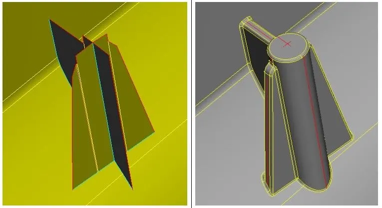
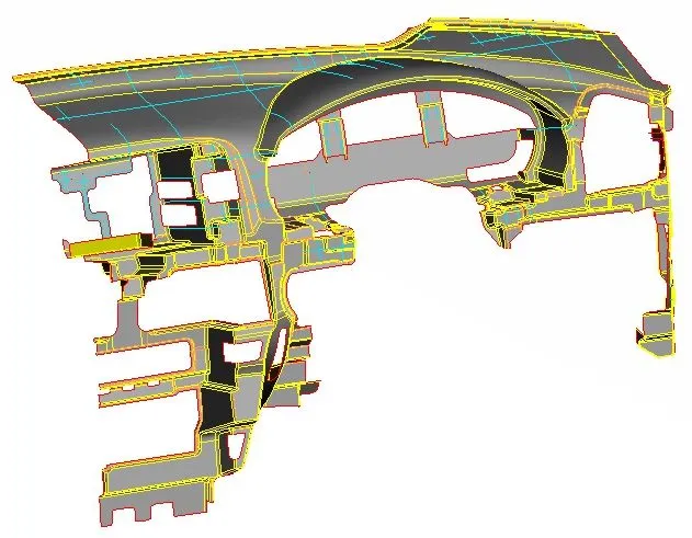
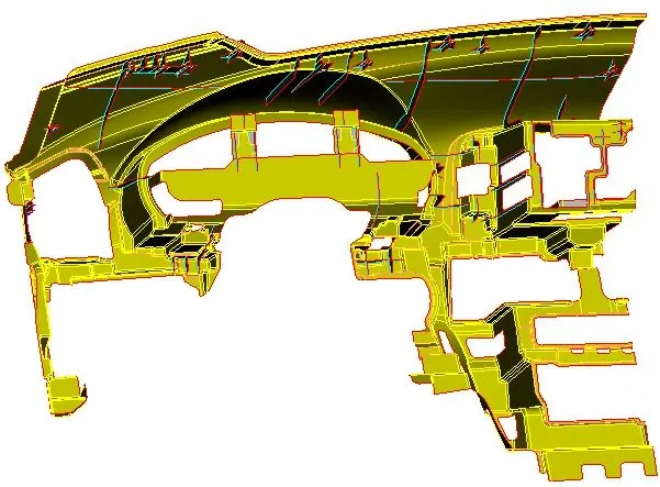
Finally, after extracting all the midsurfaces, it was checked for any geometrical issues and surfaces that were not connected were connected. The images below shows the final midsurface model.
Now before meshing, mesh parameters and quality parameters are fed into ANSA. Mesh parameters are configured by going to Utilities>Mesh parameters and quality parameters are configured by going to Utilities>Quality criteria. Configured parameters are shown in images below,
The next step is to prepare the midsurfaces for meshing. For that, switch to the Mesh module. First, the shell element length is altered by going to Perimeters>Length and all the CONS are selected and target element length 4 is fed as length value. The same is done for all the Macros (surfaces).
Next, all the areas are checked for minimum element length and altered where elements might fail for minimum length using the Macros>Cut. Similarly, CONS which are not essential to define a feature are removed by joining the surfaces using the Macros>Join tool.
The next step is to mesh the midsurface. Meshing is done surface by surface using the Best tool available under Mesh>Mesh generation>Best and, if required surfaces were further divided strategically to obtain a good mesh flow. After, generating mesh, the mesh is reconstructed by going to Mesh>Shell mesh>Reconstruct tool wherever required to improve the mesh and eliminate any off (failing) elements. After reconstructing the mesh smooth tool is used to improve mesh flow and eliminate any off elements.
It is ensured that there are no rotating quads. Also, trias are kept as low as possible. While dealing with trias, the following things should be kept in mind,
- No back to back trias touching each other
- No opposite trias
- No trias touching the edges
- No trias on a feature
- Low concentration of trias in a region
To deal with trias, the following tools are used,
- Grid>Paste, to paste the nodes and move tria backward
- Elements>Split, to split an element and move tria forward
- Elements>Swap, to move the tria left or right
- Elements>Join, to join two trias to make a quad
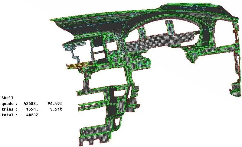
The final mesh generated is shown below,
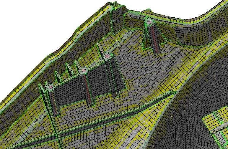
Next, the shell as solid representation is switched ON by going to Utilities>Quality Parameter>Presentation parameters>Draw shell as solid. And, it is verified that the mesh model is capturing the geometry appropriately. A section of the model is shown in the image below,
Conclusion:
Geometry cleanup, midsurface extraction, and 2D meshing of the given dashboard model were successfully done. PIDs with different thicknesses were assigned accordingly. The dashboard model had a lot of complex and converging areas, where obtaining a good mesh was very difficult. Also, because of the presence of triple CONS, there were few areas where failing elements couldn't be repaired. In total, the mesh model has 326 failing elements due to geometrical constraints. And, tria % is kept low at 3.51%.