Project 1
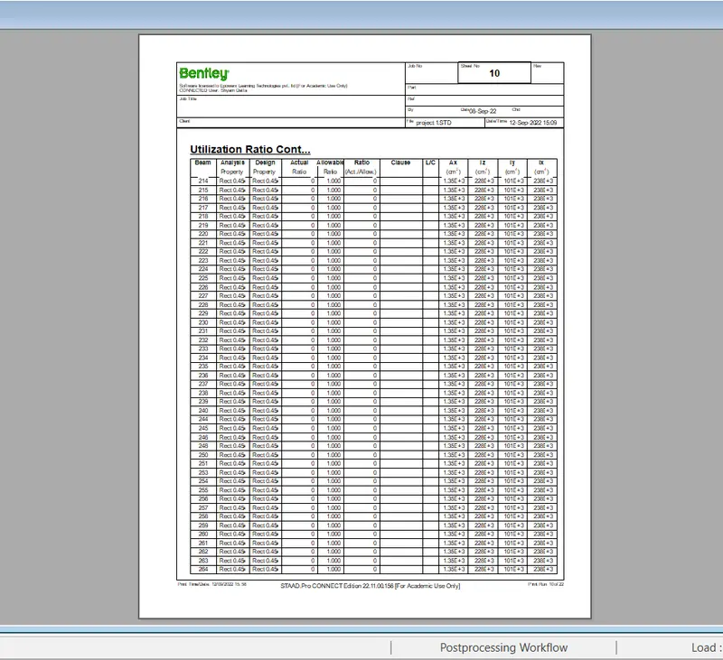
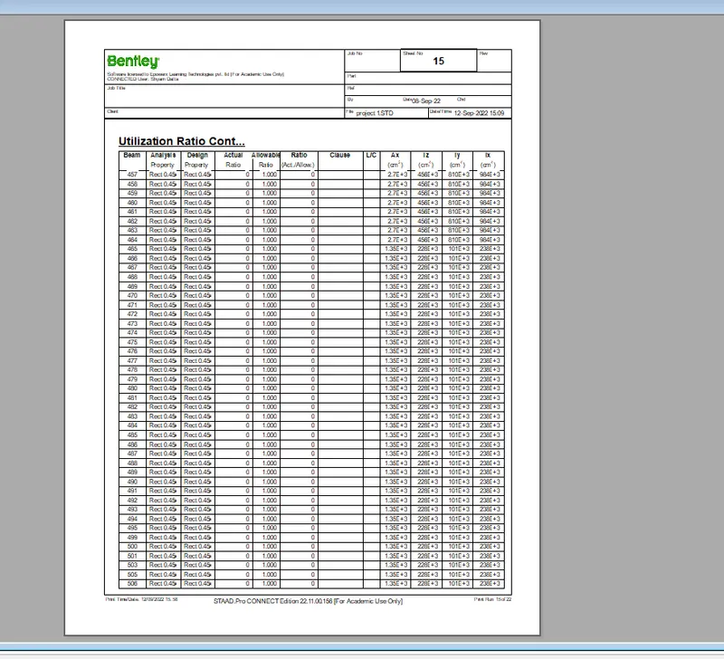
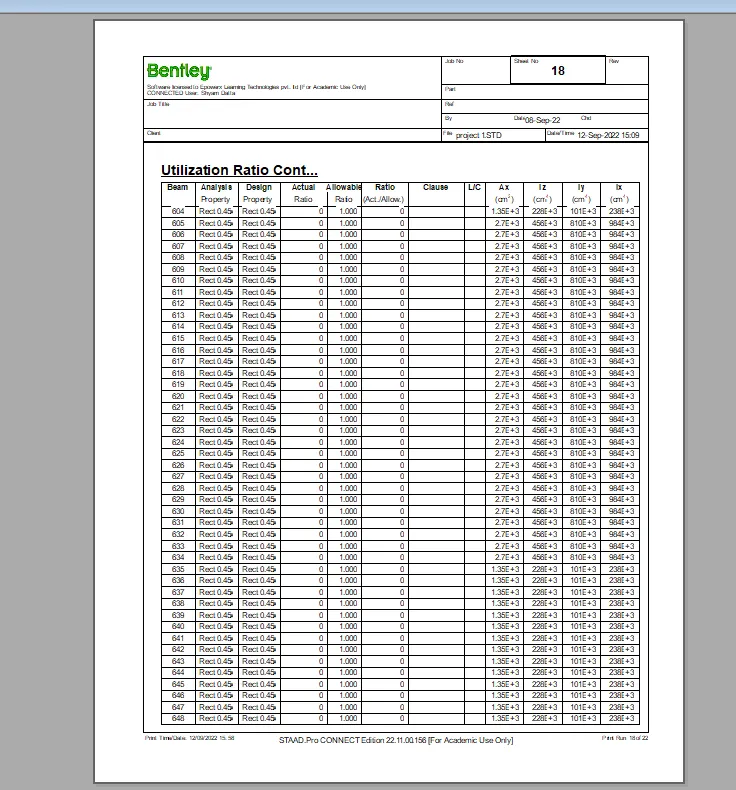
Beam column element

| Academic license user IN | ||
| CONNECTED USER: Shyam Datta |
| Project Name | : | Unassigned |
| Client Name | : | Unassigned |
| Engineer Name | : | Unassigned |
| Analysis File | : | C:\Users\shyam\OneDrive\Desktop\Shyam\project 1.STD |
| Analysis Last Modified | : | 9/12/2022 3:09:34 PM |
| Definitions Of Terms: | |||
| All forces in units kN and m | |||
| All reinforcement details like area, spacing are mm | |||
| Grade Of steel for 6 mm dia. bars is Fe250. It is irrespective of the grade of steel defined by user in column design. | |||
| Neutral axis angle for resultant design moment is with respect to local major axis. | |||
| 1 | β | = | Stiffness proportion factor at joint ( column stiffness/sum of stiffness of all members connected at joint) |
| 2 | Δu | = | Elastically computed first order lateral deflection.(Relative deflections) |
| 3 | ε1 | = | Strain at level considered, Calculated ignoring the stiffening of the concrete in tension zone |
| 4 | εm | = | Average steel strain at level considered |
| 5 | acr | = | Distance from the point considered to the surface of the nearest longitudinal bar |
| 6 | Ag | = | Gross area of the column cross section |
| 7 | Ak | = | Area of confined concrete core |
| 8 | Ash | = | Area of link cross section |
| 9 | b | = | Effective Width of Column in mm |
| 10 | B | = | Width / Smaller Dimension of Column in mm |
| 11 | d | = | Effective Depth of Column in mm |
| 12 | D | = | Depth / Larger Dimension of Column OR Diameter of Circular Column in mm |
| 13 | Dk | = | Diameter Of core measured to the outside of circular link |
| 14 | Ec | = | Modulus of elasticity of concrete |
| 15 | Es | = | Modulus of elasticity of steel |
| 16 | FcPerm | = | Permissible Stress in Concrete required in N/ (sqmm) |
| 17 | Fst | = | Stress in steel |
| 18 | FstPerm | = | Permissible Stress in Steel required in N/ (sqmm) |
| 19 | Fck | = | Characteristic compressive strength of concrete cube in N/sqmm |
| 20 | Fy | = | Yield Stress Of Steel in N/sqmm |
| 21 | h | = | Longer dimension of rectangular link measured to its outer face |
| 22 | Hu | = | Total lateral force acting within the story(Story shear) |
| 23 | Hs | = | Height of the story (Floor height) |
| 24 | k | = | Reduction factor for slenderness moments |
| 25 | Max | = | Additional moment due to slenderness about major axis (Along D) |
| 26 | May | = | Additional moment due to slenderness about minor axis (Along B) |
| 27 | Mminx | = | Moment due to minimum eccentricity along D |
| 28 | Mminy | = | Moment due to minimum eccentricity along B |
| 29 | Muv | = | Moment capacity of web portion of wall as per clause 9.4.2 and Annes A of IS 13920 - 2016 |
| 30 | Mux | = | Factored moment Along D (Momemt About Major Axis) |
| 31 | Muy | = | Factored moment Along B (Momemt About Minor Axis) |
| 32 | MCap | = | Moment capacity of section for NA angle at design Pu |
| 33 | MRes | = | Resultant design moment at angle to local major axis |
| 34 | Pb | = | Axial capacity of column along B as defined in 39.7.1.1 |
| 35 | Pd | = | Axial capacity of column along D as defined in 39.7.1.1 |
| 36 | Pu | = | Factored axial force |
| 37 | Puz | = | Axial load on column as defined in 39.6 |
| 38 | Pu_Total | = | Sum of Axial loads on all column in the story (Gravity Load) |
| 39 | Q | = | Stability Index (factor for checking sway/ non sway condition for a given story) |
| 40 | S | = | Link Spacing |
| 41 | Shear Strength Enhancement Factor | = | Multiplying factor for shear strength of concrete as per 40.2.2 |
| 42 | Vur | = | Factored resultant shear force acting on the column |
| 43 | Vux | = | Factored shear force Along B |
| 44 | Vuy | = | Factored shear force Along D |
| 45 | Wcr | = | Surface Crack Width |
| 46 | WcrPerm | = | Permissible Crack Width required in mm |
| 47 | β | = | It is a Neutral Axis angle corresponding to load angle to find out MCap |
| Code References: | |||
| IS 456 | |||
| ELEMENT | CLAUSE / table | ||
| 1 | Max area of reinforcement | : | 26.5.3.1-a & b |
| 2 | Min area of reinforcement | : | 26.5.3.1-a & b |
| 3 | Min number of bars | : | 26.5.3.1-c |
| 4 | Minimum Eccentricity Calc | : | 25.4 & 39.2 |
| 5 | Effective Length | : | 25.2 |
| 6 | Slenderness Moments | : | 25.3 & 39.7 |
| 7 | Design for axial loads | : | 39.3 |
| 8 | Design for axial loads And uniaxial bending | : | 39.5 |
| 9 | Design for axial loads And Biaxial bending | : | 39.6 |
| 10 | Design of horizontal links | : | 26.5.3.2 |
| 11 | Design shear strength | : | 40.2 |
| 12 | Stiffness Proportion Factor, β | : | E-1 |
| 13 | Stability(Index, Q) | : | E -2 |
| 14 | Crack width calculation | : | 3.8 |
| 15 | Multiplying factor to Beam Stiffness for effective length calculation | : | SP 24 1983 APPENDIX D |
| IS 13920 - 2016 | |||
| ELEMENT | CLAUSE / table | ||
| 1 | Spacing of special confining reinforcement | : | 10.4 and 7.6 |
| 2 | C/s area of special confining reinforcement | : | 7.6.1 |
| 3 | Applicability of boundary element | : | 10.4.1 |
| 4 | Muv-Moment Capacity of Web | : | Annex |
| 5 | Additional Compressive Force in BE | : | 10.4.2 |
| 6 | Check for BE in tension and compression | : | 10.4.2.1 and 10.4.3 |
| 7 | Shear include due to Beam | : | 7.5 |
| 8 | Minimum Flexural Strength of Column | : | 7.2 |
| 9 | Shear Check at Column Joint | : | 9.1 |
| 10 | Length of wall to thickness ratio | : | 10.1.3 |
| 11 | Type of wall & Minimum reinforcement | : | 10.1.4 |
| 12 | Largest diameter of longitudinal steel bar | : | 10.1.8 |
| 13 | Shear reinforcement in RC wall | : | 10.2.3 |
| 14 | Special confinement reinforcement in Boundary Element | : | 10.4.4 |
| 15 | Minimum vertical reinforcement across horizontal construction joint | : | 10.7 |
| Sway Calculation (Stability Index) |
| For Global-X Direction |
| Level | Load Name | Storey Height (m) | Gravity Load P (kN) | Relative Displacements (mm) | Storey Shear (kN) | Stability Index | Sway Condition |
| A | B | C | D | B x C / (A x D) | |||
| 0 m to 4 m | LOAD 1: EQ X+ | 4 | 41384.721 | 5.964 | 1586.708 | 0.039 | Non Sway |
| 4 m to 7.5 m | LOAD 1: EQ X+ | 3.5 | 36496.211 | 7.482 | 1576.153 | 0.049 | Sway |
| 7.5 m to 11 m | LOAD 1: EQ X+ | 3.5 | 30902.844 | 7.607 | 1537.537 | 0.044 | Sway |
| 11 m to 14.5 m | LOAD 1: EQ X+ | 3.5 | 25309.476 | 7.265 | 1454.468 | 0.036 | Non Sway |
| 14.5 m to 18 m | LOAD 1: EQ X+ | 3.5 | 19716.109 | 6.561 | 1310.129 | 0.028 | Non Sway |
| 18 m to 21.5 m | LOAD 1: EQ X+ | 3.5 | 14122.742 | 5.432 | 1087.698 | 0.02 | Non Sway |
| 21.5 m to 25 m | LOAD 1: EQ X+ | 3.5 | 8529.375 | 3.697 | 770.357 | 0.012 | Non Sway |
| 25 m to 26.5 m | LOAD 1: EQ X+ | 1.5 | 3690.709 | 0.684 | 360.781 | 0.005 | Non Sway |
| For Global-Y Direction |
| Level | Load Name | Storey Height (m) | Gravity Load P (kN) | Relative Displacements (mm) | Storey Shear (kN) | Stability Index | Sway Condition |
| A | B | C | D | B x C / (A x D) | |||
| 0 m to 4 m | LOAD 3: EQ Z+ | 4 | 41384.721 | 4.748 | 1586.708 | 0.031 | Non Sway |
| 4 m to 7.5 m | LOAD 3: EQ Z+ | 3.5 | 36496.211 | 6.944 | 1576.153 | 0.046 | Sway |
| 7.5 m to 11 m | LOAD 3: EQ Z+ | 3.5 | 30902.844 | 7.382 | 1537.537 | 0.042 | Sway |
| 11 m to 14.5 m | LOAD 3: EQ Z+ | 3.5 | 25309.476 | 7.114 | 1454.468 | 0.035 | Non Sway |
| 14.5 m to 18 m | LOAD 3: EQ Z+ | 3.5 | 19716.109 | 6.398 | 1310.129 | 0.028 | Non Sway |
| 18 m to 21.5 m | LOAD 3: EQ Z+ | 3.5 | 14122.742 | 5.238 | 1087.698 | 0.019 | Non Sway |
| 21.5 m to 25 m | LOAD 3: EQ Z+ | 3.5 | 8529.375 | 3.547 | 770.357 | 0.011 | Non Sway |
| 25 m to 26.5 m | LOAD 3: EQ Z+ | 1.5 | 3690.709 | 0.782 | 360.781 | 0.005 | Non Sway |
| General Data | |||
| Column No. | : | C1 | |
| Level | : | 0 m To 4 m | |
| Frame Type | = | Non-Ductile | |
| Response Reduction Factor | = | 3 | |
| Design Code | = | IS 456 : 2000 + IS 13920 : 2016 | |
| Grade Of Concrete | = | M25 | N/sqmm |
| Grade Of Steel (Main) | = | Fe415 | N/sqmm |
| Grade Of Steel (Shear) | = | Fe415 | N/sqmm |
| Grade Of Steel - Flexural Design | = | Fe415 | N/sqmm |
| Grade Of Steel - Shear Design | = | Fe415 | N/sqmm |
| Column B | = | 450 | mm |
| Column D | = | 600 | mm |
| Clear Cover | = | 50 | mm |
| Clear Floor Height @ B | = | 3550 | mm |
| Clear Floor Height @ D | = | 3550 | mm |
| No Of Floors | = | 1 | |
| No Of Columns In Group | = | 1 | |
| Column Type | : | UnBraced | |
| Minimum eccentricity check | : | One Axis at a Time | |
| Code defined D/B ratio | : | 4 | |
| D/B Ratio | : | 1.33 <= 4 Hence, Design as Column | |
| Flexural Design (Analysis Forces) | |||||
| Analysis Reference No. | = | 1 | |||
| Critical Analysis Load Combination | : | 85 | |||
| Load Combination | = | [71] : 0.9 (LOAD 5: DEAD) -1.5 (LOAD 2: EQ X-) | |||
| Critical Location | = | Bottom Joint | |||
| Pu | = | 440.5 | kN | ||
| Mux | = | -10.21 | kNm | ||
| Muy | = | 185.16 | kNm | ||
| Vux | = | 60.7 | kN | ||
| Vuy | = | 7.72 | kN | ||
| Effective Length Calculation |
| Calculation Along Major Axis Of Column |
| Joint | Column Stiffness | Beam Sizes | Beam Stiffness | Beta | ||
| Beam 1 (Length x Width x Depth) |
Beam 2 (Length x Width x Depth) |
Beam 1 | Beam 2 | |||
| N-m x 10^6 | mm | mm | N-m x 10^6 | N-m x 10^6 | ||
| Bottom | 202.5 | No Beam | No Beam | - | - | 1 |
| Top | 202.5 | No Beam | 5000 x 300 x 450 | - | 45.562 | 0.905 |
| Sway Condition (as per Stability Index) | = | Non Sway | |
| Effective Length Factor along Major Axis | = | 0.96 |
| Calculation Along Minor Axis Of Column |
| Joint | Column Stiffness | Beta | ||||
| Beam 1 (Length x Width x Depth) |
Beam 2 (Length x Width x Depth) |
Beam 1 | Beam 2 | |||
| N-m x 10^6 | mm | mm | N-m x 10^6 | N-m x 10^6 | ||
| Bottom | 113.906 | No Beam | No Beam | - | - | 1 |
| Top | 113.906 | 4000 x 300 x 450 | No Beam | 56.953 | - | 0.811 |
| Sway Condition (as per Stability Index) | = | Non Sway | |
| Effective Length Factor along Minor axis | = | 0.93 |
| Minimum Eccentricity Check | |||
| Since Axial Force is compressive, Min. Eccentricity check to be performed | |||
| Most critical case is with Min. Eccentricity check in X-direction | |||
| Minimum Eccentricity Along D: | |||
| Minimum Eccentricity | = | Unsupported Length / 500 + D / 30 | |
| = | 27.1 | mm | |
| Minimum Eccentricity | > | 20 | mm |
| Mminx | = | Pu x Minimum Eccentricity | |
| = | 11.94 | kNm | |
| Slenderness Check | |||
| Max Slenderness Ratio(L/B) | = | 7.89 | |
| < | 60 | (Hence Ok) | |
| Column Is Unbraced Along D | |||
| Slenderness Check Along D: | |||
| Effective Length Factor | = | 0.96 | |
| Slenderness Ratio | = | Effective Length / D | |
| = | 5.68, Column not Slender Along D | ||
| Column Is Unbraced Along B | |||
| Slenderness Check Along B: | |||
| Effective Length Factor | = | 0.93 | |
| Slenderness Ratio | = | Effective Length / B | |
| = | 7.34, Column not Slender Along B | ||
| Calculation of Design Moment |
| Direction | Manalysis | Mmin (Abs) | Mdesign | Mslndx (Abs) | Mdesign-final |
| A | B | C | E | F | |
| Major Axis - Mux | -10.21 | 11.94 | -11.94 | 0 | -11.94 |
| Minor Axis - Muy | 185.16 | --- | 185.16 | 0 | 185.16 |
| Where | ||
| A | = | Moments directly from analysis |
| B | = | Moments due to minimum eccentricity |
| C | = | Maximum of analysis moment and min. eccentricity = Max (A,B) |
| E | = | Moment due to slenderness effect |
| F | = | Final design Moment = Max(C- Top Bottom , D- Top Bottom) + E |
| Final Critical Design Forces | |||
| Pu | = | 440.5 | kN |
| Mux | = | -11.94 | kNm |
| Muy | = | 185.16 | kNm |
| Resultant Moment (Combined Action) | |||
| Moment Capacity Check | |||
| Pt Calculated | = | 0.72 | |
| Reinforcement Provided | = | 4-T16 + 10-T12 | |
| Load Angle | = | Tan-1(Muy/Mux) | |
| = | 86.31 | deg | |
| MRes | = | 185.54 | kNm |
| MCap | = | 193.11 | kNm |
| Capacity Ratio | = | MRes/ MCap | |
| = | 0.96 <= 1 | ||
| Shear Calculation | Along D | Along B |
| Critical Analysis Load Combination | 82 | 80 |
| Critical Load Combination | [68] : 0.9 (LOAD 5: DEAD) +1.5 (LOAD 3: EQ Z+) | [66] : 0.9 (LOAD 5: DEAD) +1.5 (LOAD 1: EQ X+) |
| Design shear force, Vu (kN) | -58.3421 | 60.6985 |
| Pu (kN) | 520 | 417.59 |
| Deff , Beff (mm) | 542 | 392 |
| Design shear stress, Tv | Vu / (B x Deff) | Vu / (D x Beff) |
| Tv (N/sqmm) | 0.2392 | 0.2581 |
| Pt (%) | 0.358 | 0.358 |
| Design shear strength, Tc (N/sqmm) | 0.4257 | 0.4257 |
| Shear Strength Enhancement Factor (Compressive Force) | 1 + 3 x Pu / ( B x D x Fck) | |
| 1.2311 | 1.1856 | |
| Shear Strength Enhancement Factor (Tensile Force) | - | - |
| Shear Strength Enhancement Factor (max) | 1.5 | 1.5 |
| Shear Strength Enhancement Factor | 1.2311 | 1.1856 |
| Enhanced shear strength, Tc-e (N/sqmm) | 0.524 | 0.5047 |
| Design shear check | Tv < Tc x Enhancement factor | Tv < Tc x Enhancement factor |
| Shear Links Design | Shear Links Not Required | Shear Links Not Required |
| Design Of Links | ||||
| Links in the zone where special confining links are not required | ||||
| Normal Links | ||||
| Diameter of link | = | 8 | mm | |
| > | Max. longitudinal bar dia / 4 | |||
| = | 4 | mm | ||
| Criterion for spacing of normal links | ||||
| Min. Longitudinal Bar dia X 16 | = | 192 | mm | |
| Min. dimension of column | = | 450 | mm | |
| Max. 300 mm | = | 300 | mm | |
| Provided spacing | = | 175 | mm | |
| Table For Links |
| Required | Provided | ||||
| Normal Design | Shear Design | Ductile Design | Normal Zone | Ductile Zone | |
| Link Dia. | 8 | --- | --- | 8 | --- |
| Spacing | 175 | --- | --- | 175 | --- |
| General Data | |||
| Column No. | : | C1 | |
| Level | : | 4 m To 7.5 m | |
| Frame Type | = | Non-Ductile | |
| Response Reduction Factor | = | 3 | |
| Design Code | = | IS 456 : 2000 + IS 13920 : 2016 | |
| Grade Of Concrete | = | M25 | N/sqmm |
| Grade Of Steel (Main) | = | Fe415 | N/sqmm |
| Grade Of Steel (Shear) | = | Fe415 | N/sqmm |
| Grade Of Steel - Flexural Design | = | Fe415 | N/sqmm |
| Grade Of Steel - Shear Design | = | Fe415 | N/sqmm |
| Column B | = | 450 | mm |
| Column D | = | 600 | mm |
| Clear Cover | = | 50 | mm |
| Clear Floor Height @ B | = | 3050 | mm |
| Clear Floor Height @ D | = | 3050 | mm |
| No Of Floors | = | 1 | |
| No Of Columns In Group | = | 1 | |
| Column Type | : | UnBraced | |
| Minimum eccentricity check | : | One Axis at a Time | |
| Code defined D/B ratio | : | 4 | |
| D/B Ratio | : | 1.33 <= 4 Hence, Design as Column | |
| Flexural Design (Analysis Forces) | |||||
| Analysis Reference No. | = | 95 | |||
| Critical Analysis Load Combination | : | 57 | |||
| Load Combination | = | [43] : 1.5 (LOAD 5: DEAD) +1.5 (LOAD 2: EQ X-) | |||
| Critical Location | = | Bottom Joint | |||
| Pu | = | 1620.74 | kN | ||
| Mux | = | -46.11 | kNm | ||
| Muy | = | -117.45 | kNm | ||
| Vux | = | -64.43 | kN | ||
| Vuy | = | 25.25 | kN | ||
| Effective Length Calculation |
| Calculation Along Major Axis Of Column |
| Joint | Column Stiffness | Beam Sizes | Beam Stiffness | Beta | ||
| Beam 1 (Length x Width x Depth) |
Beam 2 (Length x Width x Depth) |
Beam 1 | Beam 2 | |||
| N-m x 10^6 | mm | mm | N-m x 10^6 | N-m x 10^6 | ||
| Bottom | 231.429 | No Beam | 5000 x 300 x 450 | - | 45.562 | 0.905 |
| Top | 231.429 | No Beam | 5000 x 300 x 450 | - | 45.562 | 0.91 |
| Sway Condition (as per Stability Index) | = | Sway | |
| Effective Length Factor along Major Axis | = | 3.58 |
| Calculation Along Minor Axis Of Column |
| Joint | Column Stiffness | Beta | ||||
| Beam 1 (Length x Width x Depth) |
Beam 2 (Length x Width x Depth) |
Beam 1 | Beam 2 | |||
| N-m x 10^6 | mm | mm | N-m x 10^6 | N-m x 10^6 | ||
| Bottom | 130.179 | 4000 x 300 x 450 | No Beam | 56.953 | - | 0.811 |
| Top | 130.179 | 4000 x 300 x 450 | No Beam | 56.953 | - | 0.821 |
| Sway Condition (as per Stability Index) | = | Sway | |
| Effective Length Factor along Minor axis | = | 2.51 |
| Minimum Eccentricity Check | |||
| Since Axial Force is compressive, Min. Eccentricity check to be performed | |||
| Most critical case is with Min. Eccentricity check in X-direction | |||
| Minimum Eccentricity Along D: | |||
| Minimum Eccentricity | = | Unsupported Length / 500 + D / 30 | |
| = | 26.1 | mm | |
| Minimum Eccentricity | > | 20 | mm |
| Mminx | = | Pu x Minimum Eccentricity | |
| = | 42.3 | kNm | |
| Slenderness Check | |||
| Max Slenderness Ratio(L/B) | = | 6.78 | |
| < | 60 | (Hence Ok) | |
| Column Is Unbraced Along D | |||
| Slenderness Check Along D: | |||
| Effective Length Factor | = | 3.58 | |
| Slenderness Ratio | = | Effective Length / D | |
| = | 18.2, Column Slender Along D | ||
| Slenderness moment along D | = | (Pu D/ 2000) (Ley/D)^2 | |
| = | 161.03 kNm | ||
| Column Is Unbraced Along B | |||
| Slenderness Check Along B: | |||
| Effective Length Factor | = | 2.51 | |
| Slenderness Ratio | = | Effective Length / B | |
| = | 17.01, Column Slender Along B | ||
| Slenderness moment along B | = | (Pu B/ 2000) (Ley/B)^2 | |
| = | 105.54 | kNm | |
| Design slenderness moment along D | |||
| Puz | = | 4017.67 | kN |
| Pd | = | 1501.31 | kN |
| Reduction factor 'k' for slenderness moment | = | (Puz - Pu) / (Puz - Pd) < = 1 | |
| = | 0.95 < = 1, Hence k=0.95 | ||
| Mslndx | = | k x 161.03 | |
| = | 153.38 | kNm | |
| Design slenderness moment along B | |||
| Puz | = | 4017.67 | kN |
| Pb | = | 1405.93 | kN |
| Reduction factor 'k' for slenderness moment | = | (Puz - Pu) / (Puz - Pb) < = 1 | |
| = | 0.92 < = 1, Hence k=0.92 | ||
| Mslndy | = | k x 105.54 | |
| = | 96.86 | kNm | |
| Calculation of Design Moment |
| Direction | Manalysis | Mmin (Abs) | Mdesign | Mslndx (Abs) | Mdesign-final |
| A | B | C | E | F | |
| Major Axis - Mux | -46.11 | 42.3 | -46.11 | 153.38 | -199.5 |
| Minor Axis - Muy | -117.45 | --- | -117.45 | 96.86 | -214.31 |
| Where | ||
| A | = | Moments directly from analysis |
| B | = | Moments due to minimum eccentricity |
| C | = | Maximum of analysis moment and min. eccentricity = Max (A,B) |
| E | = | Moment due to slenderness effect |
| F | = | Final design Moment = Max(C- Top Bottom , D- Top Bottom) + E |
| Final Critical Design Forces | |||
| Pu | = | 1620.74 | kN |
| Mux | = | -199.5 | kNm |
| Muy | = | -214.31 | kNm |
| Resultant Moment (Combined Action) | |||
| Moment Capacity Check | |||
| Pt Calculated | = | 1.21 | |
| Reinforcement Provided | = | 4-T20 + 10-T16 | |
| Load Angle | = | Tan-1(Muy/Mux) | |
| = | 47.05 | deg | |
| MRes | = | 292.8 | kNm |
| MCap | = | 299.83 | kNm |
| Capacity Ratio | = | MRes/ MCap | |
| = | 0.98 <= 1 | ||
| Shear Calculation | Along D | Along B |
| Critical Analysis Load Combination | 62 | 80 |
| Critical Load Combination | [48] : 1.5 (LOAD 5: DEAD) -1.5 (LOAD 3: EQ Z+) | [66] : 0.9 (LOAD 5: DEAD) +1.5 (LOAD 1: EQ X+) |
| Design shear force, Vu (kN) | 75.4061 | 40.5187 |
| Pu (kN) | 1509.54 | 374.04 |
| Deff , Beff (mm) | 540 | 390 |
| Design shear stress, Tv | Vu / (B x Deff) | Vu / (D x Beff) |
| Tv (N/sqmm) | 0.3103 | 0.1732 |
| Pt (%) | 0.605 | 0.605 |
| Design shear strength, Tc (N/sqmm) | 0.5281 | 0.5281 |
| Shear Strength Enhancement Factor (Compressive Force) | 1 + 3 x Pu / ( B x D x Fck) | |
| 1.6709 | 1.1662 | |
| Shear Strength Enhancement Factor (Tensile Force) | - | - |
| Shear Strength Enhancement Factor (max) | 1.5 | 1.5 |
| Shear Strength Enhancement Factor | 1.5 | 1.1662 |
| Enhanced shear strength, Tc-e (N/sqmm) | 0.7921 | 0.6159 |
| Design shear check | Tv < Tc x Enhancement factor | Tv < Tc x Enhancement factor |
| Shear Links Design | Shear Links Not Required | Shear Links Not Required |
| Design Of Links | ||||
| Links in the zone where special confining links are not required | ||||
| Normal Links | ||||
| Diameter of link | = | 8 | mm | |
| > | Max. longitudinal bar dia / 4 | |||
| = | 5 | mm | ||
| Criterion for spacing of normal links | ||||
| Min. Longitudinal Bar dia X 16 | = | 256 | mm | |
| Min. dimension of column | = | 450 | mm | |
| Max. 300 mm | = | 300 | mm | |
| Provided spacing | = | 250 | mm | |
| Table For Links |
| Required | Provided | ||||
| Normal Design | Shear Design | Ductile Design | Normal Zone | Ductile Zone | |
| Link Dia. | 8 | --- | --- | 8 | --- |
| Spacing | 250 | --- | --- | 250 | --- |
| General Data | |||
| Column No. | : | C1 | |
| Level | : | 7.5 m To 11 m | |
| Frame Type | = | Non-Ductile | |
| Response Reduction Factor | = | 3 | |
| Design Code | = | IS 456 : 2000 + IS 13920 : 2016 | |
| Grade Of Concrete | = | M25 | N/sqmm |
| Grade Of Steel (Main) | = | Fe415 | N/sqmm |
| Grade Of Steel (Shear) | = | Fe415 | N/sqmm |
| Grade Of Steel - Flexural Design | = | Fe415 | N/sqmm |
| Grade Of Steel - Shear Design | = | Fe415 | N/sqmm |
| Column B | = | 450 | mm |
| Column D | = | 600 | mm |
| Clear Cover | = | 50 | mm |
| Clear Floor Height @ B | = | 3050 | mm |
| Clear Floor Height @ D | = | 3050 | mm |
| No Of Floors | = | 1 | |
| No Of Columns In Group | = | 1 | |
| Column Type | : | UnBraced | |
| Minimum eccentricity check | : | One Axis at a Time | |
| Code defined D/B ratio | : | 4 | |
| D/B Ratio | : | 1.33 <= 4 Hence, Design as Column | |
| Flexural Design (Analysis Forces) | |||||
| Analysis Reference No. | = | 180 | |||
| Critical Analysis Load Combination | : | 57 | |||
| Load Combination | = | [43] : 1.5 (LOAD 5: DEAD) +1.5 (LOAD 2: EQ X-) | |||
| Critical Location | = | Top Joint | |||
| Pu | = | 1302.59 | kN | ||
| Mux | = | 43.34 | kNm | ||
| Muy | = | 111.85 | kNm | ||
| Vux | = | -62.91 | kN | ||
| Vuy | = | 24.64 | kN | ||
| Effective Length Calculation |
| Calculation Along Major Axis Of Column |
| Joint | Column Stiffness | Beam Sizes | Beam Stiffness | Beta | ||
| Beam 1 (Length x Width x Depth) |
Beam 2 (Length x Width x Depth) |
Beam 1 | Beam 2 | |||
| N-m x 10^6 | mm | mm | N-m x 10^6 | N-m x 10^6 | ||
| Bottom | 231.429 | No Beam | 5000 x 300 x 450 | - | 45.562 | 0.91 |
| Top | 231.429 | No Beam | 5000 x 300 x 450 | - | 45.562 | 0.91 |
| Sway Condition (as per Stability Index) | = | Sway | |
| Effective Length Factor along Major Axis | = | 3.63 |
| Calculation Along Minor Axis Of Column |
| Joint | Column Stiffness | Beta | ||||
| Beam 1 (Length x Width x Depth) |
Beam 2 (Length x Width x Depth) |
Beam 1 | Beam 2 | |||
| N-m x 10^6 | mm | mm | N-m x 10^6 | N-m x 10^6 | ||
| Bottom | 130.179 | 4000 x 300 x 450 | No Beam | 56.953 | - | 0.821 |
| Top | 130.179 | 4000 x 300 x 450 | No Beam | 56.953 | - | 0.821 |
| Sway Condition (as per Stability Index) | = | Sway | |
| Effective Length Factor along Minor axis | = | 2.55 |
| Minimum Eccentricity Check | |||
| Since Axial Force is compressive, Min. Eccentricity check to be performed | |||
| Most critical case is with Min. Eccentricity check in X-direction | |||
| Minimum Eccentricity Along D: | |||
| Minimum Eccentricity | = | Unsupported Length / 500 + D / 30 | |
| = | 26.1 | mm | |
| Minimum Eccentricity | > | 20 | mm |
| Mminx | = | Pu x Minimum Eccentricity | |
| = | 34 | kNm | |
| Slenderness Check | |||
| Max Slenderness Ratio(L/B) | = | 6.78 | |
| < | 60 | (Hence Ok) | |
| Column Is Unbraced Along D | |||
| Slenderness Check Along D: | |||
| Effective Length Factor | = | 3.63 | |
| Slenderness Ratio | = | Effective Length / D | |
| = | 18.45, Column Slender Along D | ||
| Slenderness moment along D | = | (Pu D/ 2000) (Ley/D)^2 | |
| = | 133.06 kNm | ||
| Column Is Unbraced Along B | |||
| Slenderness Check Along B: | |||
| Effective Length Factor | = | 2.55 | |
| Slenderness Ratio | = | Effective Length / B | |
| = | 17.28, Column Slender Along B | ||
| Slenderness moment along B | = | (Pu B/ 2000) (Ley/B)^2 | |
| = | 87.55 | kNm | |
| Design slenderness moment along D | |||
| Puz | = | 3829.18 | kN |
| Pd | = | 1490.31 | kN |
| Reduction factor 'k' for slenderness moment | = | (Puz - Pu) / (Puz - Pd) < = 1 | |
| = | 1.08 > = 1, Hence k=1 | ||
| Mslndx | = | k x 133.06 | |
| = | 133.06 | kNm | |
| Design slenderness moment along B | |||
| Puz | = | 3829.18 | kN |
| Pb | = | 1413.16 | kN |
| Reduction factor 'k' for slenderness moment | = | (Puz - Pu) / (Puz - Pb) < = 1 | |
| = | 1.05 < = 1, Hence k=1.05 | ||
| Mslndy | = | k x 87.55 | |
| = | 87.55 | kNm | |
| Calculation of Design Moment |
| Direction | Manalysis | Mmin (Abs) | Mdesign | Mslndx (Abs) | Mdesign-final |
| A | B | C | E | F | |
| Major Axis - Mux | 43.34 | 34 | 43.34 | 133.06 | 176.4 |
| Minor Axis - Muy | 111.85 | --- | 111.85 | 87.55 | 199.4 |
| Where | ||
| A | = | Moments directly from analysis |
| B | = | Moments due to minimum eccentricity |
| C | = | Maximum of analysis moment and min. eccentricity = Max (A,B) |
| E | = | Moment due to slenderness effect |
| F | = | Final design Moment = Max(C- Top Bottom , D- Top Bottom) + E |
| Final Critical Design Forces | |||
| Pu | = | 1302.59 | kN |
| Mux | = | 176.4 | kNm |
| Muy | = | 199.4 | kNm |
| Resultant Moment (Combined Action) | |||
| Moment Capacity Check | |||
| Pt Calculated | = | 0.98 | |
| Reinforcement Provided | = | 12-T16 + 2-T12 | |
| Load Angle | = | Tan-1(Muy/Mux) | |
| = | 48.5 | deg | |
| MRes | = | 266.22 | kNm |
| MCap | = | 276.94 | kNm |
| Capacity Ratio | = | MRes/ MCap | |
| = | 0.96 <= 1 | ||
| Shear Calculation | Along D | Along B |
| Critical Analysis Load Combination | 86 | 80 |
| Critical Load Combination | [72] : 0.9 (LOAD 5: DEAD) -1.5 (LOAD 3: EQ Z+) | [66] : 0.9 (LOAD 5: DEAD) +1.5 (LOAD 1: EQ X+) |
| Design shear force, Vu (kN) | 62.4027 | 39.9418 |
| Pu (kN) | 836.65 | 332.93 |
| Deff , Beff (mm) | 542 | 392 |
| Design shear stress, Tv | Vu / (B x Deff) | Vu / (D x Beff) |
| Tv (N/sqmm) | 0.2559 | 0.1698 |
| Pt (%) | 0.489 | 0.489 |
| Design shear strength, Tc (N/sqmm) | 0.4843 | 0.4843 |
| Shear Strength Enhancement Factor (Compressive Force) | 1 + 3 x Pu / ( B x D x Fck) | |
| 1.3718 | 1.148 | |
| Shear Strength Enhancement Factor (Tensile Force) | - | - |
| Shear Strength Enhancement Factor (max) | 1.5 | 1.5 |
| Shear Strength Enhancement Factor | 1.3718 | 1.148 |
| Enhanced shear strength, Tc-e (N/sqmm) | 0.6644 | 0.556 |
| Design shear check | Tv < Tc x Enhancement factor | Tv < Tc x Enhancement factor |
| Shear Links Design | Shear Links Not Required | Shear Links Not Required |
| Design Of Links | ||||
| Links in the zone where special confining links are not required | ||||
| Normal Links | ||||
| Diameter of link | = | 8 | mm | |
| > | Max. longitudinal bar dia / 4 | |||
| = | 4 | mm | ||
| Criterion for spacing of normal links | ||||
| Min. Longitudinal Bar dia X 16 | = | 192 | mm | |
| Min. dimension of column | = | 450 | mm | |
| Max. 300 mm | = | 300 | mm | |
| Provided spacing | = | 175 | mm | |
| Table For Links |
| Required | Provided | ||||
| Normal Design | Shear Design | Ductile Design | Normal Zone | Ductile Zone | |
| Link Dia. | 8 | --- | --- | 8 | --- |
| Spacing | 175 | --- | --- | 175 | --- |
| General Data | |||
| Column No. | : | C1 | |
| Level | : | 11 m To 14.5 m | |
| Frame Type | = | Non-Ductile | |
| Response Reduction Factor | = | 3 | |
| Design Code | = | IS 456 : 2000 + IS 13920 : 2016 | |
| Grade Of Concrete | = | M25 | N/sqmm |
| Grade Of Steel (Main) | = | Fe415 | N/sqmm |
| Grade Of Steel (Shear) | = | Fe415 | N/sqmm |
| Grade Of Steel - Flexural Design | = | Fe415 | N/sqmm |
| Grade Of Steel - Shear Design | = | Fe415 | N/sqmm |
| Column B | = | 450 | mm |
| Column D | = | 600 | mm |
| Clear Cover | = | 50 | mm |
| Clear Floor Height @ B | = | 3050 | mm |
| Clear Floor Height @ D | = | 3050 | mm |
| No Of Floors | = | 1 | |
| No Of Columns In Group | = | 1 | |
| Column Type | : | UnBraced | |
| Minimum eccentricity check | : | One Axis at a Time | |
| Code defined D/B ratio | : | 4 | |
| D/B Ratio | : | 1.33 <= 4 Hence, Design as Column | |
| Flexural Design (Analysis Forces) | |||||
| Analysis Reference No. | = | 265 | |||
| Critical Analysis Load Combination | : | 57 | |||
| Load Combination | = | [43] : 1.5 (LOAD 5: DEAD) +1.5 (LOAD 2: EQ X-) | |||
| Critical Location | = | Top Joint | |||
| Pu | = | 1019.51 | kN | ||
| Mux | = | 44.31 | kNm | ||
| Muy | = | 110.1 | kNm | ||
| Vux | = | -59.79 | kN | ||
| Vuy | = | 25.21 | kN | ||
| Effective Length Calculation |
| Calculation Along Major Axis Of Column |
| Joint | Column Stiffness | Beam Sizes | Beam Stiffness | Beta | ||
| Beam 1 (Length x Width x Depth) |
Beam 2 (Length x Width x Depth) |
Beam 1 | Beam 2 | |||
| N-m x 10^6 | mm | mm | N-m x 10^6 | N-m x 10^6 | ||
| Bottom | 231.429 | No Beam | 5000 x 300 x 450 | - | 45.562 | 0.91 |
| Top | 231.429 | No Beam | 5000 x 300 x 450 | - | 45.562 | 0.91 |
| Sway Condition (as per Stability Index) | = | Non Sway | |
| Effective Length Factor along Major Axis | = | 0.93 |
| Calculation Along Minor Axis Of Column |
| Joint | Column Stiffness | Beta | ||||
| Beam 1 (Length x Width x Depth) |
Beam 2 (Length x Width x Depth) |
Beam 1 | Beam 2 | |||
| N-m x 10^6 | mm | mm | N-m x 10^6 | N-m x 10^6 | ||
| Bottom | 130.179 | 4000 x 300 x 450 | No Beam | 56.953 | - | 0.821 |
| Top | 130.179 | 4000 x 300 x 450 | No Beam | 56.953 | - | 0.821 |
| Sway Condition (as per Stability Index) | = | Non Sway | |
| Effective Length Factor along Minor axis | = | 0.87 |
| Minimum Eccentricity Check | |||
| Since Axial Force is compressive, Min. Eccentricity check to be performed | |||
| Most critical case is with Min. Eccentricity check in X-direction | |||
| Minimum Eccentricity Along D: | |||
| Minimum Eccentricity | = | Unsupported Length / 500 + D / 30 | |
| = | 26.1 | mm | |
| Minimum Eccentricity | > | 20 | mm |
| Mminx | = | Pu x Minimum Eccentricity | |
| = | 26.61 | kNm | |
| Slenderness Check | |||
| Max Slenderness Ratio(L/B) | = | 6.78 | |
| < | 60 | (Hence Ok) | |
| Column Is Unbraced Along D | |||
| Slenderness Check Along D: | |||
| Effective Length Factor | = | 0.93 | |
| Slenderness Ratio | = | Effective Length / D | |
| = | 4.73, Column not Slender Along D | ||
| Column Is Unbraced Along B | |||
| Slenderness Check Along B: | |||
| Effective Length Factor | = | 0.87 | |
| Slenderness Ratio | = | Effective Length / B | |
| = | 5.9, Column not Slender Along B | ||
| Calculation of Design Moment |
| Direction | Manalysis | Mmin (Abs) | Mdesign | Mslndx (Abs) | Mdesign-final |
| A | B | C | E | F | |
| Major Axis - Mux | 44.31 | 26.61 | 44.31 | 0 | 44.31 |
| Minor Axis - Muy | 110.1 | --- | 110.1 | 0 | 110.1 |
| Where | ||
| A | = | Moments directly from analysis |
| B | = | Moments due to minimum eccentricity |
| C | = | Maximum of analysis moment and min. eccentricity = Max (A,B) |
| E | = | Moment due to slenderness effect |
| F | = | Final design Moment = Max(C- Top Bottom , D- Top Bottom) + E |
| Final Critical Design Forces | |||
| Pu | = | 1019.51 | kN |
| Mux | = | 44.31 | kNm |
| Muy | = | 110.1 | kNm |
| Resultant Moment (Combined Action) | |||
| Moment Capacity Check | |||
| Pt Calculated | = | 0.42 | |
| Reinforcement Provided | = | 10-T12 | |
| Load Angle | = | Tan-1(Muy/Mux) | |
| = | 68.08 | deg | |
| MRes | = | 118.68 | kNm |
| MCap | = | 197.95 | kNm |
| Capacity Ratio | = | MRes/ MCap | |
| = | 0.6 <= 1 | ||
| Shear Calculation | Along D | Along B |
| Critical Analysis Load Combination | 86 | 84 |
| Critical Load Combination | [72] : 0.9 (LOAD 5: DEAD) -1.5 (LOAD 3: EQ Z+) | [70] : 0.9 (LOAD 5: DEAD) -1.5 (LOAD 1: EQ X+) |
| Design shear force, Vu (kN) | 59.1315 | -53.8068 |
| Pu (kN) | 653.79 | 692.77 |
| Deff , Beff (mm) | 544 | 394 |
| Design shear stress, Tv | Vu / (B x Deff) | Vu / (D x Beff) |
| Tv (N/sqmm) | 0.2416 | 0.2276 |
| Pt (%) | 0.209 | 0.209 |
| Design shear strength, Tc (N/sqmm) | 0.3376 | 0.3376 |
| Shear Strength Enhancement Factor (Compressive Force) | 1 + 3 x Pu / ( B x D x Fck) | |
| 1.2906 | 1.3079 | |
| Shear Strength Enhancement Factor (Tensile Force) | - | - |
| Shear Strength Enhancement Factor (max) | 1.5 | 1.5 |
| Shear Strength Enhancement Factor | 1.2906 | 1.3079 |
| Enhanced shear strength, Tc-e (N/sqmm) | 0.4356 | 0.4415 |
| Design shear check | Tv < Tc x Enhancement factor | Tv < Tc x Enhancement factor |
| Shear Links Design | Shear Links Not Required | Shear Links Not Required |
| Design Of Links | ||||
| Links in the zone where special confining links are not required | ||||
| Normal Links | ||||
| Diameter of link | = | 8 | mm | |
| > | Max. longitudinal bar dia / 4 | |||
| = | 3 | mm | ||
| Criterion for spacing of normal links | ||||
| Min. Longitudinal Bar dia X 16 | = | 192 | mm | |
| Min. dimension of column | = | 450 | mm | |
| Max. 300 mm | = | 300 | mm | |
| Provided spacing | = | 175 | mm | |
| Table For Links |
| Required | Provided | ||||
| Normal Design | Shear Design | Ductile Design | Normal Zone | Ductile Zone | |
| Link Dia. | 8 | --- | --- | 8 | --- |
| Spacing | 175 | --- | --- | 175 | --- |
| General Data | |||
| Column No. | : | C1 | |
| Level | : | 14.5 m To 18 m | |
| Frame Type | = | Non-Ductile | |
| Response Reduction Factor | = | 3 | |
| Design Code | = | IS 456 : 2000 + IS 13920 : 2016 | |
| Grade Of Concrete | = | M25 | N/sqmm |
| Grade Of Steel (Main) | = | Fe415 | N/sqmm |
| Grade Of Steel (Shear) | = | Fe415 | N/sqmm |
| Grade Of Steel - Flexural Design | = | Fe415 | N/sqmm |
| Grade Of Steel - Shear Design | = | Fe415 | N/sqmm |
| Column B | = | 450 | mm |
| Column D | = | 600 | mm |
| Clear Cover | = | 50 | mm |
| Clear Floor Height @ B | = | 3050 | mm |
| Clear Floor Height @ D | = | 3050 | mm |
| No Of Floors | = | 1 | |
| No Of Columns In Group | = | 1 | |
| Column Type | : | UnBraced | |
| Minimum eccentricity check | : | One Axis at a Time | |
| Code defined D/B ratio | : | 4 | |
| D/B Ratio | : | 1.33 <= 4 Hence, Design as Column | |
| Flexural Design (Analysis Forces) | |||||
| Analysis Reference No. | = | 350 | |||
| Critical Analysis Load Combination | : | 57 | |||
| Load Combination | = | [43] : 1.5 (LOAD 5: DEAD) +1.5 (LOAD 2: EQ X-) | |||
| Critical Location | = | Top Joint | |||
| Pu | = | 742.27 | kN | ||
| Mux | = | 44.8 | kNm | ||
| Muy | = | 105.29 | kNm | ||
| Vux | = | -55.07 | kN | ||
| Vuy | = | 25.54 | kN | ||
| Effective Length Calculation |
| Calculation Along Major Axis Of Column |
| Joint | Column Stiffness | Beam Sizes | Beam Stiffness | Beta | ||
| Beam 1 (Length x Width x Depth) |
Beam 2 (Length x Width x Depth) |
Beam 1 | Beam 2 | |||
| N-m x 10^6 | mm | mm | N-m x 10^6 | N-m x 10^6 | ||
| Bottom | 231.429 | No Beam | 5000 x 300 x 450 | - | 45.562 | 0.91 |
| Top | 231.429 | No Beam | 5000 x 300 x 450 | - | 45.562 | 0.91 |
| Sway Condition (as per Stability Index) | = | Non Sway | |
| Effective Length Factor along Major Axis | = | 0.93 |
| Calculation Along Minor Axis Of Column |
| Joint | Column Stiffness | Beta | ||||
| Beam 1 (Length x Width x Depth) |
Beam 2 (Length x Width x Depth) |
Beam 1 | Beam 2 | |||
| N-m x 10^6 | mm | mm | N-m x 10^6 | N-m x 10^6 | ||
| Bottom | 130.179 | 4000 x 300 x 450 | No Beam | 56.953 | - | 0.821 |
| Top | 130.179 | 4000 x 300 x 450 | No Beam | 56.953 | - | 0.821 |
| Sway Condition (as per Stability Index) | = | Non Sway | |
| Effective Length Factor along Minor axis | = | 0.87 |
| Minimum Eccentricity Check | |||
| Since Axial Force is compressive, Min. Eccentricity check to be performed | |||
| Most critical case is with Min. Eccentricity check in X-direction | |||
| Minimum Eccentricity Along D: | |||
| Minimum Eccentricity | = | Unsupported Length / 500 + D / 30 | |
| = | 26.1 | mm | |
| Minimum Eccentricity | > | 20 | mm |
| Mminx | = | Pu x Minimum Eccentricity | |
| = | 19.37 | kNm | |
| Slenderness Check | |||
| Max Slenderness Ratio(L/B) | = | 6.78 | |
| < | 60 | (Hence Ok) | |
| Column Is Unbraced Along D | |||
| Slenderness Check Along D: | |||
| Effective Length Factor | = | 0.93 | |
| Slenderness Ratio | = | Effective Length / D | |
| = | 4.73, Column not Slender Along D | ||
| Column Is Unbraced Along B | |||
| Slenderness Check Along B: | |||
| Effective Length Factor | = | 0.87 | |
| Slenderness Ratio | = | Effective Length / B | |
| = | 5.9, Column not Slender Along B | ||
| Calculation of Design Moment |
| Direction | Manalysis | Mmin (Abs) | Mdesign | Mslndx (Abs) | Mdesign-final |
| A | B | C | E | F | |
| Major Axis - Mux | 44.8 | 19.37 | 44.8 | 0 | 44.8 |
| Minor Axis - Muy | 105.29 | --- | 105.29 | 0 | 105.29 |
| Where | ||
| A | = | Moments directly from analysis |
| B | = | Moments due to minimum eccentricity |
| C | = | Maximum of analysis moment and min. eccentricity = Max (A,B) |
| E | = | Moment due to slenderness effect |
| F | = | Final design Moment = Max(C- Top Bottom , D- Top Bottom) + E |
| Final Critical Design Forces | |||
| Pu | = | 742.27 | kN |
| Mux | = | 44.8 | kNm |
| Muy | = | 105.29 | kNm |
| Resultant Moment (Combined Action) | |||
| Moment Capacity Check | |||
| Pt Calculated | = | 0.42 | |
| Reinforcement Provided | = | 10-T12 | |
| Load Angle | = | Tan-1(Muy/Mux) | |
| = | 66.95 | deg | |
| MRes | = | 114.43 | kNm |
| MCap | = | 182.75 | kNm |
| Capacity Ratio | = | MRes/ MCap | |
| = | 0.63 <= 1 | ||
| Shear Calculation | Along D | Along B |
| Critical Analysis Load Combination | 62 | 84 |
| Critical Load Combination | [48] : 1.5 (LOAD 5: DEAD) -1.5 (LOAD 3: EQ Z+) | [70] : 0.9 (LOAD 5: DEAD) -1.5 (LOAD 1: EQ X+) |
| Design shear force, Vu (kN) | 64.5996 | -48.957 |
| Pu (kN) | 719.12 | 498.21 |
| Deff , Beff (mm) | 544 | 394 |
| Design shear stress, Tv | Vu / (B x Deff) | Vu / (D x Beff) |
| Tv (N/sqmm) | 0.2639 | 0.2071 |
| Pt (%) | 0.209 | 0.209 |
| Design shear strength, Tc (N/sqmm) | 0.3376 | 0.3376 |
| Shear Strength Enhancement Factor (Compressive Force) | 1 + 3 x Pu / ( B x D x Fck) | |
| 1.3196 | 1.2214 | |
| Shear Strength Enhancement Factor (Tensile Force) | - | - |
| Shear Strength Enhancement Factor (max) | 1.5 | 1.5 |
| Shear Strength Enhancement Factor | 1.3196 | 1.2214 |
| Enhanced shear strength, Tc-e (N/sqmm) | 0.4454 | 0.4123 |
| Design shear check | Tv < Tc x Enhancement factor | Tv < Tc x Enhancement factor |
| Shear Links Design | Shear Links Not Required | Shear Links Not Required |
| Design Of Links | ||||
| Links in the zone where special confining links are not required | ||||
| Normal Links | ||||
| Diameter of link | = | 8 | mm | |
| > | Max. longitudinal bar dia / 4 | |||
| = | 3 | mm | ||
| Criterion for spacing of normal links | ||||
| Min. Longitudinal Bar dia X 16 | = | 192 | mm | |
| Min. dimension of column | = | 450 | mm | |
| Max. 300 mm | = | 300 | mm | |
| Provided spacing | = | 175 | mm | |
| Table For Links |
| Required | Provided | ||||
| Normal Design | Shear Design | Ductile Design | Normal Zone | Ductile Zone | |
| Link Dia. | 8 | --- | --- | 8 | --- |
| Spacing | 175 | --- | --- | 175 | --- |
| General Data | |||
| Column No. | : | C1 | |
| Level | : | 18 m To 21.5 m | |
| Frame Type | = | Non-Ductile | |
| Response Reduction Factor | = | 3 | |
| Design Code | = | IS 456 : 2000 + IS 13920 : 2016 | |
| Grade Of Concrete | = | M25 | N/sqmm |
| Grade Of Steel (Main) | = | Fe415 | N/sqmm |
| Grade Of Steel (Shear) | = | Fe415 | N/sqmm |
| Grade Of Steel - Flexural Design | = | Fe415 | N/sqmm |
| Grade Of Steel - Shear Design | = | Fe415 | N/sqmm |
| Column B | = | 450 | mm |
| Column D | = | 600 | mm |
| Clear Cover | = | 50 | mm |
| Clear Floor Height @ B | = | 3050 | mm |
| Clear Floor Height @ D | = | 3050 | mm |
| No Of Floors | = | 1 | |
| No Of Columns In Group | = | 1 | |
| Column Type | : | UnBraced | |
| Minimum eccentricity check | : | One Axis at a Time | |
| Code defined D/B ratio | : | 4 | |
| D/B Ratio | : | 1.33 <= 4 Hence, Design as Column | |
| Flexural Design (Analysis Forces) | |||||
| Analysis Reference No. | = | 435 | |||
| Critical Analysis Load Combination | : | 57 | |||
| Load Combination | = | [43] : 1.5 (LOAD 5: DEAD) +1.5 (LOAD 2: EQ X-) | |||
| Critical Location | = | Top Joint | |||
| Pu | = | 474.86 | kN | ||
| Mux | = | 45.5 | kNm | ||
| Muy | = | 97.44 | kNm | ||
| Vux | = | -48.1 | kN | ||
| Vuy | = | 25.97 | kN | ||
| Effective Length Calculation |
| Calculation Along Major Axis Of Column |
| Joint | Column Stiffness | Beam Sizes | Beam Stiffness | Beta | ||
| Beam 1 (Length x Width x Depth) |
Beam 2 (Length x Width x Depth) |
Beam 1 | Beam 2 | |||
| N-m x 10^6 | mm | mm | N-m x 10^6 | N-m x 10^6 | ||
| Bottom | 231.429 | No Beam | 5000 x 300 x 450 | - | 45.562 | 0.91 |
| Top | 231.429 | No Beam | 5000 x 300 x 450 | - | 45.562 | 0.91 |
| Sway Condition (as per Stability Index) | = | Non Sway | |
| Effective Length Factor along Major Axis | = | 0.93 |
| Calculation Along Minor Axis Of Column |
| Joint | Column Stiffness | Beta | ||||
| Beam 1 (Length x Width x Depth) |
Beam 2 (Length x Width x Depth) |
Beam 1 | Beam 2 | |||
| N-m x 10^6 | mm | mm | N-m x 10^6 | N-m x 10^6 | ||
| Bottom | 130.179 | 4000 x 300 x 450 | No Beam | 56.953 | - | 0.821 |
| Top | 130.179 | 4000 x 300 x 450 | No Beam | 56.953 | - | 0.821 |
| Sway Condition (as per Stability Index) | = | Non Sway | |
| Effective Length Factor along Minor axis | = | 0.87 |
| Minimum Eccentricity Check | |||
| Since Axial Force is compressive, Min. Eccentricity check to be performed | |||
| Most critical case is with Min. Eccentricity check in X-direction | |||
| Minimum Eccentricity Along D: | |||
| Minimum Eccentricity | = | Unsupported Length / 500 + D / 30 | |
| = | 26.1 | mm | |
| Minimum Eccentricity | > | 20 | mm |
| Mminx | = | Pu x Minimum Eccentricity | |
| = | 12.39 | kNm | |
| Slenderness Check | |||
| Max Slenderness Ratio(L/B) | = | 6.78 | |
| < | 60 | (Hence Ok) | |
| Column Is Unbraced Along D | |||
| Slenderness Check Along D: | |||
| Effective Length Factor | = | 0.93 | |
| Slenderness Ratio | = | Effective Length / D | |
| = | 4.73, Column not Slender Along D | ||
| Column Is Unbraced Along B | |||
| Slenderness Check Along B: | |||
| Effective Length Factor | = | 0.87 | |
| Slenderness Ratio | = | Effective Length / B | |
| = | 5.9, Column not Slender Along B | ||
| Calculation of Design Moment |
| Direction | Manalysis | Mmin (Abs) | Mdesign | Mslndx (Abs) | Mdesign-final |
| A | B | C | E | F | |
| Major Axis - Mux | 45.5 | 12.39 | 45.5 | 0 | 45.5 |
| Minor Axis - Muy | 97.44 | --- | 97.44 | 0 | 97.44 |
| Where | ||
| A | = | Moments directly from analysis |
| B | = | Moments due to minimum eccentricity |
| C | = | Maximum of analysis moment and min. eccentricity = Max (A,B) |
| E | = | Moment due to slenderness effect |
| F | = | Final design Moment = Max(C- Top Bottom , D- Top Bottom) + E |
| Final Critical Design Forces | |||
| Pu | = | 474.86 | kN |
| Mux | = | 45.5 | kNm |
| Muy | = | 97.44 | kNm |
| Resultant Moment (Combined Action) | |||
| Moment Capacity Check | |||
| Pt Calculated | = | 0.42 | |
| Reinforcement Provided | = | 10-T12 | |
| Load Angle | = | Tan-1(Muy/Mux) | |
| = | 64.97 | deg | |
| MRes | = | 107.53 | kNm |
| MCap | = | 159.47 | kNm |
| Capacity Ratio | = | MRes/ MCap | |
| = | 0.67 <= 1 | ||
| Shear Calculation | Along D | Along B |
| Critical Analysis Load Combination | 62 | 60 |
| Critical Load Combination | [48] : 1.5 (LOAD 5: DEAD) -1.5 (LOAD 3: EQ Z+) | [46] : 1.5 (LOAD 5: DEAD) -1.5 (LOAD 1: EQ X+) |
| Design shear force, Vu (kN) | 58.1864 | -48.1002 |
| Pu (kN) | 464.97 | 474.86 |
| Deff , Beff (mm) | 544 | 394 |
| Design shear stress, Tv | Vu / (B x Deff) | Vu / (D x Beff) |
| Tv (N/sqmm) | 0.2377 | 0.2035 |
| Pt (%) | 0.209 | 0.209 |
| Design shear strength, Tc (N/sqmm) | 0.3376 | 0.3376 |
| Shear Strength Enhancement Factor (Compressive Force) | 1 + 3 x Pu / ( B x D x Fck) | |
| 1.2067 | 1.211 | |
| Shear Strength Enhancement Factor (Tensile Force) | - | - |
| Shear Strength Enhancement Factor (max) | 1.5 | 1.5 |
| Shear Strength Enhancement Factor | 1.2067 | 1.211 |
| Enhanced shear strength, Tc-e (N/sqmm) | 0.4073 | 0.4088 |
| Design shear check | Tv < Tc x Enhancement factor | Tv < Tc x Enhancement factor |
| Shear Links Design | Shear Links Not Required | Shear Links Not Required |
| Design Of Links | ||||
| Links in the zone where special confining links are not required | ||||
| Normal Links | ||||
| Diameter of link | = | 8 | mm | |
| > | Max. longitudinal bar dia / 4 | |||
| = | 3 | mm | ||
| Criterion for spacing of normal links | ||||
| Min. Longitudinal Bar dia X 16 | = | 192 | mm | |
| Min. dimension of column | = | 450 | mm | |
| Max. 300 mm | = | 300 | mm | |
| Provided spacing | = | 175 | mm | |
| Table For Links |
| Required | Provided | ||||
| Normal Design | Shear Design | Ductile Design | Normal Zone | Ductile Zone | |
| Link Dia. | 8 | --- | --- | 8 | --- |
| Spacing | 175 | --- | --- | 175 | --- |
| General Data | |||
| Column No. | : | C1 | |
| Level | : | 21.5 m To 25 m | |
| Frame Type | = | Non-Ductile | |
| Response Reduction Factor | = | 3 | |
| Design Code | = | IS 456 : 2000 + IS 13920 : 2016 | |
| Grade Of Concrete | = | M25 | N/sqmm |
| Grade Of Steel (Main) | = | Fe415 | N/sqmm |
| Grade Of Steel (Shear) | = | Fe415 | N/sqmm |
| Grade Of Steel - Flexural Design | = | Fe415 | N/sqmm |
| Grade Of Steel - Shear Design | = | Fe415 | N/sqmm |
| Column B | = | 450 | mm |
| Column D | = | 600 | mm |
| Clear Cover | = | 50 | mm |
| Clear Floor Height @ B | = | 3050 | mm |
| Clear Floor Height @ D | = | 3050 | mm |
| No Of Floors | = | 1 | |
| No Of Columns In Group | = | 1 | |
| Column Type | : | UnBraced | |
| Minimum eccentricity check | : | One Axis at a Time | |
| Code defined D/B ratio | : | 4 | |
| D/B Ratio | : | 1.33 <= 4 Hence, Design as Column | |
| Flexural Design (Analysis Forces) | |||||
| Analysis Reference No. | = | 520 | |||
| Critical Analysis Load Combination | : | 59 | |||
| Load Combination | = | [45] : 1.5 (LOAD 5: DEAD) +1.5 (LOAD 4: EQ Z-) | |||
| Critical Location | = | Top Joint | |||
| Pu | = | 221.99 | kN | ||
| Mux | = | 122.28 | kNm | ||
| Muy | = | 23.64 | kNm | ||
| Vux | = | -14.52 | kN | ||
| Vuy | = | 48.48 | kN | ||
| Effective Length Calculation |
| Calculation Along Major Axis Of Column |
| Joint | Column Stiffness | Beam Sizes | Beam Stiffness | Beta | ||
| Beam 1 (Length x Width x Depth) |
Beam 2 (Length x Width x Depth) |
Beam 1 | Beam 2 | |||
| N-m x 10^6 | mm | mm | N-m x 10^6 | N-m x 10^6 | ||
| Bottom | 231.429 | No Beam | 5000 x 300 x 450 | - | 45.562 | 0.91 |
| Top | 231.429 | No Beam | 5000 x 300 x 450 | - | 45.562 | 0.944 |
| Sway Condition (as per Stability Index) | = | Non Sway | |
| Effective Length Factor along Major Axis | = | 0.94 |
| Calculation Along Minor Axis Of Column |
| Joint | Column Stiffness | Beta | ||||
| Beam 1 (Length x Width x Depth) |
Beam 2 (Length x Width x Depth) |
Beam 1 | Beam 2 | |||
| N-m x 10^6 | mm | mm | N-m x 10^6 | N-m x 10^6 | ||
| Bottom | 130.179 | 4000 x 300 x 450 | No Beam | 56.953 | - | 0.821 |
| Top | 130.179 | 4000 x 300 x 450 | No Beam | 56.953 | - | 0.884 |
| Sway Condition (as per Stability Index) | = | Non Sway | |
| Effective Length Factor along Minor axis | = | 0.89 |
| Minimum Eccentricity Check | |||
| Since Axial Force is compressive, Min. Eccentricity check to be performed | |||
| Most critical case is with Min. Eccentricity check in X-direction | |||
| Minimum Eccentricity Along D: | |||
| Minimum Eccentricity | = | Unsupported Length / 500 + D / 30 | |
| = | 26.1 | mm | |
| Minimum Eccentricity | > | 20 | mm |
| Mminx | = | Pu x Minimum Eccentricity | |
| = | 5.79 | kNm | |
| Slenderness Check | |||
| Max Slenderness Ratio(L/B) | = | 6.78 | |
| < | 60 | (Hence Ok) | |
| Column Is Unbraced Along D | |||
| Slenderness Check Along D: | |||
| Effective Length Factor | = | 0.94 | |
| Slenderness Ratio | = | Effective Length / D | |
| = | 4.78, Column not Slender Along D | ||
| Column Is Unbraced Along B | |||
| Slenderness Check Along B: | |||
| Effective Length Factor | = | 0.89 | |
| Slenderness Ratio | = | Effective Length / B | |
| = | 6.03, Column not Slender Along B | ||
| Calculation of Design Moment |
| Direction | Manalysis | Mmin (Abs) | Mdesign | Mslndx (Abs) | Mdesign-final |
| A | B | C | E | F | |
| Major Axis - Mux | 122.28 | 5.79 | 122.28 | 0 | 122.28 |
| Minor Axis - Muy | 23.64 | --- | 23.64 | 0 | 23.64 |
| Where | ||
| A | = | Moments directly from analysis |
| B | = | Moments due to minimum eccentricity |
| C | = | Maximum of analysis moment and min. eccentricity = Max (A,B) |
| E | = | Moment due to slenderness effect |
| F | = | Final design Moment = Max(C- Top Bottom , D- Top Bottom) + E |
| Final Critical Design Forces | |||
| Pu | = | 221.99 | kN |
| Mux | = | 122.28 | kNm |
| Muy | = | 23.64 | kNm |
| Resultant Moment (Combined Action) | |||
| Moment Capacity Check | |||
| Pt Calculated | = | 0.42 | |
| Reinforcement Provided | = | 10-T12 | |
| Load Angle | = | Tan-1(Muy/Mux) | |
| = | 10.94 | deg | |
| MRes | = | 124.55 | kNm |
| MCap | = | 156.17 | kNm |
| Capacity Ratio | = | MRes/ MCap | |
| = | 0.8 <= 1 | ||
| Shear Calculation | Along D | Along B |
| Critical Analysis Load Combination | 62 | 60 |
| Critical Load Combination | [48] : 1.5 (LOAD 5: DEAD) -1.5 (LOAD 3: EQ Z+) | [46] : 1.5 (LOAD 5: DEAD) -1.5 (LOAD 1: EQ X+) |
| Design shear force, Vu (kN) | 48.478 | -38.4055 |
| Pu (kN) | 221.99 | 222.1 |
| Deff , Beff (mm) | 544 | 394 |
| Design shear stress, Tv | Vu / (B x Deff) | Vu / (D x Beff) |
| Tv (N/sqmm) | 0.198 | 0.1625 |
| Pt (%) | 0.209 | 0.209 |
| Design shear strength, Tc (N/sqmm) | 0.3376 | 0.3376 |
| Shear Strength Enhancement Factor (Compressive Force) | 1 + 3 x Pu / ( B x D x Fck) | |
| 1.0987 | 1.0987 | |
| Shear Strength Enhancement Factor (Tensile Force) | - | - |
| Shear Strength Enhancement Factor (max) | 1.5 | 1.5 |
| Shear Strength Enhancement Factor | 1.0987 | 1.0987 |
| Enhanced shear strength, Tc-e (N/sqmm) | 0.3709 | 0.3709 |
| Design shear check | Tv < Tc x Enhancement factor | Tv < Tc x Enhancement factor |
| Shear Links Design | Shear Links Not Required | Shear Links Not Required |
| Design Of Links | ||||
| Links in the zone where special confining links are not required | ||||
| Normal Links | ||||
| Diameter of link | = | 8 | mm | |
| > | Max. longitudinal bar dia / 4 | |||
| = | 3 | mm | ||
| Criterion for spacing of normal links | ||||
| Min. Longitudinal Bar dia X 16 | = | 192 | mm | |
| Min. dimension of column | = | 450 | mm | |
| Max. 300 mm | = | 300 | mm | |
| Provided spacing | = | 175 | mm | |
| Table For Links |
| Required | Provided | ||||
| Normal Design | Shear Design | Ductile Design | Normal Zone | Ductile Zone | |
| Link Dia. | 8 | --- | --- | 8 | --- |
| Spacing | 175 | --- | --- | 175 | --- |
| General Data | |||
| Column No. | : | C1 | |
| Level | : | 25 m To 26.5 m | |
| Frame Type | = | Non-Ductile | |
| Response Reduction Factor | = | 3 | |
| Design Code | = | IS 456 : 2000 + IS 13920 : 2016 | |
| Grade Of Concrete | = | M25 | N/sqmm |
| Grade Of Steel (Main) | = | Fe415 | N/sqmm |
| Grade Of Steel (Shear) | = | Fe415 | N/sqmm |
| Grade Of Steel - Flexural Design | = | Fe415 | N/sqmm |
| Grade Of Steel - Shear Design | = | Fe415 | N/sqmm |
| Column B | = | 450 | mm |
| Column D | = | 600 | mm |
| Clear Cover | = | 50 | mm |
| Clear Floor Height @ B | = | 1050 | mm |
| Clear Floor Height @ D | = | 1050 | mm |
| No Of Floors | = | 1 | |
| No Of Columns In Group | = | 1 | |
| Column Type | : | UnBraced | |
| Minimum eccentricity check | : | One Axis at a Time | |
| Code defined D/B ratio | : | 4 | |
| D/B Ratio | : | 1.33 <= 4 Hence, Design as Column | |
| Flexural Design (Analysis Forces) | |||||
| Analysis Reference No. | = | 605 | |||
| Critical Analysis Load Combination | : | 59 | |||
| Load Combination | = | [45] : 1.5 (LOAD 5: DEAD) +1.5 (LOAD 4: EQ Z-) | |||
| Critical Location | = | Top Joint | |||
| Pu | = | 75.95 | kN | ||
| Mux | = | 65.03 | kNm | ||
| Muy | = | 23.83 | kNm | ||
| Vux | = | -27.06 | kN | ||
| Vuy | = | 32.49 | kN | ||
| Effective Length Calculation |
| Calculation Along Major Axis Of Column |
| Joint | Column Stiffness | Beam Sizes | Beam Stiffness | Beta | ||
| Beam 1 (Length x Width x Depth) |
Beam 2 (Length x Width x Depth) |
Beam 1 | Beam 2 | |||
| N-m x 10^6 | mm | mm | N-m x 10^6 | N-m x 10^6 | ||
| Bottom | 540 | No Beam | 5000 x 300 x 450 | - | 45.562 | 0.944 |
| Top | 540 | No Beam | 5000 x 300 x 450 | - | 45.562 | 0.922 |
| Sway Condition (as per Stability Index) | = | Non Sway | |
| Effective Length Factor along Major Axis | = | 0.95 |
| Calculation Along Minor Axis Of Column |
| Joint | Column Stiffness | Beta | ||||
| Beam 1 (Length x Width x Depth) |
Beam 2 (Length x Width x Depth) |
Beam 1 | Beam 2 | |||
| N-m x 10^6 | mm | mm | N-m x 10^6 | N-m x 10^6 | ||
| Bottom | 303.75 | 4000 x 300 x 450 | No Beam | 56.953 | - | 0.884 |
| Top | 303.75 | 4000 x 300 x 450 | No Beam | 56.953 | - | 0.842 |
| Sway Condition (as per Stability Index) | = | Non Sway | |
| Effective Length Factor along Minor axis | = | 0.9 |
| Minimum Eccentricity Check | |||
| Since Axial Force is compressive, Min. Eccentricity check to be performed | |||
| Most critical case is with Min. Eccentricity check in X-direction | |||
| Minimum Eccentricity Along D: | |||
| Minimum Eccentricity | = | Unsupported Length / 500 + D / 30 | |
| = | 22.1 | mm | |
| Minimum Eccentricity | > | 20 | mm |
| Mminx | = | Pu x Minimum Eccentricity | |
| = | 1.68 | kNm | |
| Slenderness Check | |||
| Max Slenderness Ratio(L/B) | = | 2.33 | |
| < | 60 | (Hence Ok) | |
| Column Is Unbraced Along D | |||
| Slenderness Check Along D: | |||
| Effective Length Factor | = | 0.95 | |
| Slenderness Ratio | = | Effective Length / D | |
| = | 1.66, Column not Slender Along D | ||
| Column Is Unbraced Along B | |||
| Slenderness Check Along B: | |||
| Effective Length Factor | = | 0.9 | |
| Slenderness Ratio | = | Effective Length / B | |
| = | 2.1, Column not Slender Along B | ||
| Calculation of Design Moment |
| Direction | Manalysis | Mmin (Abs) | Mdesign | Mslndx (Abs) | Mdesign-final |
| A | B | C | E | F | |
| Major Axis - Mux | 65.03 | 1.68 | 65.03 | 0 | 65.03 |
| Minor Axis - Muy | 23.83 | --- | 23.83 | 0 | 23.83 |
| Where | ||
| A | = | Moments directly from analysis |
| B | = | Moments due to minimum eccentricity |
| C | = | Maximum of analysis moment and min. eccentricity = Max (A,B) |
| E | = | Moment due to slenderness effect |
| F | = | Final design Moment = Max(C- Top Bottom , D- Top Bottom) + E |
| Final Critical Design Forces | |||
| Pu | = | 75.95 | kN |
| Mux | = | 65.03 | kNm |
| Muy | = | 23.83 | kNm |
| Resultant Moment (Combined Action) | |||
| Moment Capacity Check | |||
| Pt Calculated | = | 0.42 | |
| Reinforcement Provided | = | 10-T12 | |
| Load Angle | = | Tan-1(Muy/Mux) | |
| = | 20.12 | deg | |
| MRes | = | 69.26 | kNm |
| MCap | = | 123.55 | kNm |
| Capacity Ratio | = | MRes/ MCap | |
| = | 0.56 <= 1 | ||
| Shear Calculation | Along D | Along B |
| Critical Analysis Load Combination | 15 | 15 |
| Critical Load Combination | [1] : 1.5 (LOAD 5: DEAD) +1.5 (LOAD 6: LIVE) | [1] : 1.5 (LOAD 5: DEAD) +1.5 (LOAD 6: LIVE) |
| Design shear force, Vu (kN) | 45.3561 | -32.991 |
| Pu (kN) | 78.04 | 78.04 |
| Deff , Beff (mm) | 544 | 394 |
| Design shear stress, Tv | Vu / (B x Deff) | Vu / (D x Beff) |
| Tv (N/sqmm) | 0.1853 | 0.1396 |
| Pt (%) | 0.209 | 0.209 |
| Design shear strength, Tc (N/sqmm) | 0.3376 | 0.3376 |
| Shear Strength Enhancement Factor (Compressive Force) | 1 + 3 x Pu / ( B x D x Fck) | |
| 1.0347 | 1.0347 | |
| Shear Strength Enhancement Factor (Tensile Force) | - | - |
| Shear Strength Enhancement Factor (max) | 1.5 | 1.5 |
| Shear Strength Enhancement Factor | 1.0347 | 1.0347 |
| Enhanced shear strength, Tc-e (N/sqmm) | 0.3493 | 0.3493 |
| Design shear check | Tv < Tc x Enhancement factor | Tv < Tc x Enhancement factor |
| Shear Links Design | Shear Links Not Required | Shear Links Not Required |
| Design Of Links | ||||
| Links in the zone where special confining links are not required | ||||
| Normal Links | ||||
| Diameter of link | = | 8 | mm | |
| > | Max. longitudinal bar dia / 4 | |||
| = | 3 | mm | ||
| Criterion for spacing of normal links | ||||
| Min. Longitudinal Bar dia X 16 | = | 192 | mm | |
| Min. dimension of column | = | 450 | mm | |
| Max. 300 mm | = | 300 | mm | |
| Provided spacing | = | 175 | mm | |
| Table For Links |
| Required | Provided | ||||
| Normal Design | Shear Design | Ductile Design | Normal Zone | Ductile Zone | |
| Link Dia. | 8 | --- | --- | 8 | --- |
| Spacing | 175 | --- | --- | ||
foundation
Isolated Footing Design (IS 456-2000)
| Footing No. | Group ID | Foundation Geometry | ||
| - | - | Length | Width | Thickness |
| 1 | 1 | 2.20m | 2.20m | 0.70m |
| Footing No. | Footing Reinforcement | Pedestal Reinforcement | ||||
| - | Bottom Reinforcement(Mz) | Bottom Reinforcement(Mx) | Top Reinforcement(Mz) | Top Reinforcement(Mx) | Main Steel | Trans Steel |
| 1 | Ø20 @ 415 mm c/c | Ø20 @ 415 mm c/c | N/A | N/A | N/A | |
Input Values
Footing Geometry
| Design Type | : | Calculate Dimension with user specified minimums as starting value | ||
| Minimum Footing Length - X(Fl) | : | 2000.00 | mm | |
| Minimum Footing Width - Z (Fw) | : | 2000.00 | mm | |
| Minimum Footing Thickness(Ft) | : | 700.00 | mm | |
| Eccentricity along X (Oxd) | : | 0.00 | mm | |
| Eccentricity along Z (Ozd) | : | 0.00 | mm |
Column Dimensions
| Column Shape | : | Rectangular | ||
| Column Length - X (Pl) | : | 0.45 | m | |
| Column Width - Z (Pw) | : | 0.60 | m | |
Pedestal
| Include Pedestal | : | No | |
| Pedestal Shape | : | N/A |
Design Parameters
Concrete and Rebar Properties
| Unit Weight of Concrete | : | 24.00 | kN/m3 |
| Strength of Concrete | : | 50.00 | N/mm2 |
| Yield Strength of Steel | : | 350.00 | N/mm2 |
| Minimum Bar Size | : | Ø20 | |
| Maximum Bar Size | : | Ø20 | |
| Pedestal Minimum Bar Size | : | Ø8 | |
| Pedestal Maximum Bar Size | : | Ø40 | |
| Minimum Bar Spacing | : | 100.00 | mm |
| Maximum Bar Spacing | : | 450.00 | mm |
| Pedestal Clear Cover (P, CL) | : | 50.00 | mm |
| Footing Clear Cover (F, CL) | : | 50.00 | mm |
Soil Properties
| Unit Weight | : | 17.60 kN/m3 | |||
| Base Value of Soil Bearing Capacity | : | 180.00 kPa | |||
| Multiplying factor for soil bearing capacity for ultimate loads | : | 1.70 | |||
| Soil Bearing Capacity Type | : | Gross Bearing Capacity | |||
| Soil Surcharge | : | 0.00 kN/m2 | |||
| Height of Soil above Footing | : | 500.00 mm | |||
| Type of Depth | : | Fixed Top | |||
| Minimum Percentage of Slab area in Contact for Service Loads | : | 0.00 | |||
| Minimum Percentage of Slab area in Contact for Ultimate Loads | : | 0.00 | |||
Sliding and Overturning
| Coefficient of Friction | : | 0.50 | ||
| Factor of Safety Against Sliding | : | 1.50 | ||
| Factor of Safety Against Overturning | : | 1.50 |
Global Settings
| Top Reinforcement Option : | Calculate only when foundation is subjected to uplift forces |
| Concrete Design Option : | Net Pressure(Gross Pressure - Self Weight Pressure) |
| ------------------------------------------------------ |
| Design Calculations |
| Load Combination/s- Service Stress Level | |||||
|---|---|---|---|---|---|
| Load Combination Number | Load Combination Title | Load Case Multiplier (a) | Soil Bearing Factor (b) | Self Weight Factor (c) | Code |
| a - Value specified in the Load Multiplier table b - Value specified in the Pile/Soil Bearing Capacity Factors table c - Value specified in the Apply Self Weight and Dead Weight Factor table |
|||||
| 5 | DEAD | 1.00 | 1.00 | 1.00 | - |
| 6 | LIVE | 1.00 | 1.00 | 1.00 | - |
| Load Combination/s- Strength Level | |||||
|---|---|---|---|---|---|
| Load Combination Number | Load Combination Title | Load Case Multiplier (a) | Soil Bearing Factor (b) | Self Weight Factor (c) | Code |
| a - Value specified in the Load Multiplier table b - Value specified in the Pile/Soil Bearing Capacity Factors table c - Value specified in the Apply Self Weight and Dead Weight Factor table |
|||||
| 5 | DEAD | 1.00 | 1.00 | 1.00 | - |
| 6 | LIVE | 1.00 | 1.00 | 1.00 | - |
Before consideration of self weight and load multiplier table
Moments are About the center of Column / Pedestal (does not include moments caused by lateral loads)
For the loads shown in this table, the sign convention is the same as that for JOINT LOADS in STAAD.Pro when global Y is the vertical axis.
| Applied Loads for Column - Service Stress Level | |||||
| Load Case | Fx (kN) |
Fy (kN) Downwards is negative Upwards is positive |
Fz (kN) |
Mx (kNm) |
Mz (kNm) |
| 5 | -2.94 | -661.80 | -5.58 | -7.69 | 3.99 |
| 6 | -0.01 | -76.83 | 0.05 | -0.04 | 0.03 |
| Applied Loads for Column - Strength Level | |||||
| Load Case | Fx (kN) |
Fy (kN) Downwards is negative Upwards is positive |
Fz (kN) |
Mx (kNm) |
Mz (kNm) |
| 5 | -2.94 | -661.80 | -5.58 | -7.69 | 3.99 |
| 6 | -0.01 | -76.83 | 0.05 | -0.04 | 0.03 |
| ------------------------------------------------------ |
| Footing Size |
Initial Length (Lo) = 2.00 m Initial Width (Wo) = 2.00 m
|
Area from initial length and width, Ao
|
= | Lo×Wo | = | 4.00 | m2 |
|
Min. area required from bearing pressure, Amin
|
= | Pqmax | = | 4.23 | m2 |
|
Note: Amin is an initial estimation.
|
|
|
P = Vertical load from column + selfweight of footing + weight of soil.
|
|
|
qmax = Respective Factored Bearing Capacity.
|
| Final Footing Size |
Length (L2) = 2.20 m Governing Load Case : # 5 Width (W2) = 2.20 m Governing Load Case : # 5 Depth (D2) = 0.70 m Area (A2) = 4.84 m2 Depth is governed by Ultimate Load Case (Service check is performed with footing thickness requirements from concrete check) Final Soil Height = 0.50 m
Weight of the footing + pedestal (if any) = 81.31 kN Weight of the soil above the footing (dry) = 40.22 kN Uplift force due to buoyancy = 0.00 kN Effect due to adhesion = 0.00 kN
------------------------------------------------------
Load Case Pressure at top left corner
(kN/m2)Pressure at top right corner
(kN/m2)Pressure at bottom right corner
(kN/m2)Pressure at bottom left corner
(kN/m2)Area of footing in uplift (Au)
(m2)Gross Bearing Capacity
(kN/m2)5 171.7895 164.9758 151.9013 158.7151 0.00 180.0000 5 171.7895 164.9758 151.9013 158.7151 0.00 180.0000 5 171.7895 164.9758 151.9013 158.7151 0.00 180.0000 5 171.7895 164.9758 151.9013 158.7151 0.00 180.0000 If Au is zero, there is no uplift and no pressure adjustment is necessary. Otherwise, to account for uplift, areas of negative pressure will be set to zero and the pressure will be redistributed to remaining corners.
Summary of adjusted Gross Pressures at Four Corners
Load Case Pressure at
top left corner
(kN/m2)Pressure at
top right corner
(kN/m2)Pressure at
bottom right corner
(kN/m2)Pressure at
bottom left corner
(kN/m2)Gross Bearing Capacity
(kN/m2)5 171.7895 164.9758 151.9013 158.7151 180.0000 5 171.7895 164.9758 151.9013 158.7151 180.0000 5 171.7895 164.9758 151.9013 158.7151 180.0000 5 171.7895 164.9758 151.9013 158.7151 180.0000
Details of Out-of-Contact Area
(If Any)
Governing load case = N/A Plan area of footing = 4.84 sq.m Area not in contact with soil = = 0.00 sq.m % of total area not in contact = 0.00%
| ------------------------------------------------------ |
| - | Factor of safety against sliding | Factor of safety against overturning | |||||
|---|---|---|---|---|---|---|---|
| Load Case No. | Along X-Direction | Along Z-Direction | Resultant | Required FOS | About X-Direction | About Z-Direction | Required FOS |
| 5 | 133.09 | 70.13 | 62.04 | 1.50 | 74.27 | 142.52 | 1.50 |
| 6 | N/A | N/A | N/A | 1.50 | N/A | N/A | 1.50 |
| Critical Load Case for Sliding along X-Direction | : | 5 | |
| Governing Disturbing Force | : | -2.94 | kN |
| Governing Restoring Force | : | 391.67 | kN |
| Minimum Sliding Ratio for the Critical Load Case | : | 133.09 | |
| Critical Load Case for Overturning About X-Direction | : | 5 | |
| Governing Overturning Moment | : | -11.60 | kNm |
| Governing Resisting Moment | : | 861.65 | kNm |
| Minimum Overturning Ratio for the Critical Load Case | : | 74.27 |
| Critical Load Case for Sliding along Z-Direction | : | 5 | |
| Governing Disturbing Force | : | -5.58 | kN |
| Governing Restoring Force | : | 391.67 | kN |
| Minimum Sliding Ratio for the Critical Load Case | : | 70.13 | |
| Critical Load Case for Overturning About Z-Direction | : | 5 | |
| Governing Overturning Moment | : | 6.05 | kNm |
| Governing Resisting Moment : | : | 861.65 | kNm |
| Minimum Overturning Ratio for the Critical Load Case | : | 142.52 |
| Critical Load Case for Sliding along Resultant Direction : | : | 5 | |
| Governing Disturbing Force | : | 6.31 | kN |
| Governing Restoring Force | : | 391.67 | kN |
| Minimum Sliding Ratio for the Critical Load Case | : | 62.04 |
| ------------------------------------------------------ |
| Top Reinforcement Design Requirement |
| Top Reinforcement needs to be provided because of resultant negative pressure coming from net pressure calculations for bending. |
Ultimate Gross PressuresThe base pressures reported in this table and the area of footing in contact include the effect of buoyancy (if any).
Load Case / Load Combination ID Pressure at top left corner
(kN/m2)Pressure at top right corner
(kN/m2)Pressure at bottom right corner
(kN/m2)Pressure at bottom left corner
(kN/m2)Gross Factored Bearing Capacity For Ultimate Load Case
(kN/m2)Area of footing in Contact with soil (Au)
(m2)5 171.7895 164.9758 151.9013 158.7151 305.9999 4.84 6 41.0106 40.9704 40.9561 40.9963 305.9999 4.84
| Minimum Required Contact Area for Ultimate Loads | : | 0.00 | m2 |
Actual Area in Contact for all ultimate load cases exceeds the minimum required. Hence Safe
Maximum Corner Pressure from all ultimate load cases is less than the allowable. Hence Safe
Critical Load Case = #5 Effective Depth = D-(cc+1.5 × db) = 0.62 m Governing moment (Mu) = = 117.24 kNm
As Per IS 456 2000 ANNEX G G-1.1C Limiting Factor1 (Kumax) = 700[1100+(0.87 × fy )] = 0.50 Limiting Factor2 (Rumax) = 0.36×fck×kumax×(1-0.42×kumax) = 7093.26 kN/m2 Limiting Moment Of Resistance (Mumax) = Rumax×B×d2 = 5998.52 kNm Mu <= Mumax hence, safe
Critical Load Case = #5 Effective Depth = D-(cc+1.5 × db) = 0.62 m Governing moment (Mu) = = 99.71 kNm
As Per IS 456 2000 ANNEX G G-1.1C Limiting Factor1 (Kumax) = 700[1100+(0.87×fy )] = 0.50 Limiting Factor2 (Rumax) = 0.36×fck×kumax×(1-0.42×kumax) = 7093.26 kN/m2 Limiting Moment Of Resistance (Mumax) = Rumax × B × d2 = 5998.52 kNm Mu <= Mumax hence, safe
| ------------------------------------------------------ |
(Shear Plane Parallel to Global X Axis)
|
1.1 m1.1 m0.18 m0.18 mPlanXZ
|
Critical Load Case = # 5 Distance of critical section from top left corner along Z, DZ = 0.18 m Shear Force(S) = 52.84 kN Shear Stress(Tv) = 38.74 kN/m2 Percentage Of Steel(Pt) = 0.1382
As Per IS 456 2000 Clause 40 Table 19 Shear Strength Of Concrete(Tc) = 300.00 kN/m2 Shear Enhancement Factor (if considered) is applied to (Tc), as per IS456 -2000 Clause No 40.5.1 and Fig 24 Tv< Tc hence, safe
(Shear Plane Parallel to Global Z Axis)
|
1.1 m1.1 m0.255 m0.255 mPlanXZ
|
Critical Load Case = # 5 Distance of critical section from top left corner along X, DX = 0.25 m Shear Force(S) = 76.59 kN Shear Stress(Tv) = 56.15 kN/m2 Percentage Of Steel(Pt) = 0.14 As Per IS 456 2000 Clause 40 Table 19 Shear Strength Of Concrete(Tc) = 300.00 kN/m2 Shear Enhancement Factor (if considered) is applied to (Tc), as per IS456 -2000 Clause No 40.5.1 and Fig 24 Tv< Tc hence, safe
|
1.1 m1.1 m0.315 mPlanXZ
|
Critical Load Case = #5 Shear Force(S) = 502.43 kN Shear Stress(Tv) = 172.62 kN/m2 As Per IS 456 2000 Clause 31.6.3.1
Ks = min[0.5+β,1] = 1.00 Shear Strength(Tc) = 0.25×fck = 1767.77 kN/m2
Ks x Tc = 1767.77 kN/m2
Tv<= Ks x Tc hence, safe
| ------------------------------------------------------ |
Bar diameter corresponding to max bar size (db) = 20 mm As Per IS 456 2000 Clause 26.2.1
Development Length(ld) = db×0.87×fy4×τbd = 0.45 m Available Development Length(ldb) = (B-b)2-cc = 0.83 m ldb >=ld hence, safe
Bar diameter corresponding to max bar size(db) = 20 mm As Per IS 456 2000 Clause 26.2.1
Development Length(ld) = db×0.87×fy4×τbd = 0.45 m Available Development Length(ldb) = (H-h)2-cc = 0.75 m ldb >=ld hence, safe
Design For Bottom Reinforcement Parallel to Z Axis
|
6 - 20 mmXZ
|
For moment About X Axis (Mx) As Per IS 456 2000 Clause 26.5.2.1 Critical Load Case = #5 Minimum Area of Steel (Astmin) = 1848 mm2 Calculated Area of Steel (Ast) = 1848 mm2 Note - "Area of Steel required" reported here is the larger value between the calculated area of steel and minimum steel required as per code stipulations Provided Area of Steel (Ast,Provided) = 1885 mm2 Ast,Provided >= Astmin Hence OK.
Selected bar Size (db) = Ø20 Minimum spacing allowed (Smin) = 100.00 mm Selected spacing (S) = 416.00 mm Smin<= S <= Smax and selected bar size < selected maximum bar size. Hence OK. Based on spacing reinforcement increment; provided reinforcement is
Ø20 @ 415mm o.c.
Design For Bottom Reinforcement Parallel to X Axis
|
6 - 20 mmXZ
|
For moment About Z Axis (Mz) As Per IS 456 2000 Clause 26.5.2.1 Critical Load Case = #5 Minimum Area of Steel (Astmin) = 1848 mm2 Calculated Area of Steel (Ast) = 1848 mm2 Note - "Area of Steel required" reported here is the larger value between the calculated area of steel and minimum steel required as per code stipulations Provided Area of Steel (Ast,Provided) = 1885 mm2 Ast,Provided >= Astmin Hence OK.
Selected bar Size (db) = Ø20 Minimum spacing allowed (Smin) = 100.00 mm Selected spacing (S) = 416.00 mm Smin<= S <= Smax and selected bar size < selected maximum bar size. Hence OK. Based on spacing reinforcement increment; provided reinforcement is
Ø20 @ 415mm o.c.
| Modulus of Elasticity of Concrete(Ec) | = | 35355339.06 | kN/m2 | Clause No. 6.2.3.1 |
| Modulus of Elasticity of Steel(Es) | = | 200000000.00 | kN/m2 | Annexure F |
| Depth of Neutral Axis(Xu) | = | 0.33 | m | Annexure G, Clause No. G-1.1.a |
| Effective MOI(Ieff) | = | 26907495888.50 | mm4 | |
| Average Steel Strain at Considered Level(Ɛm) | = | 0.00 X 10⁻⁵ | ||
| Distance from Nearest Tension Rod (acr) | = | 0.22 | m | |
| Crack Width (Wcr) | = | 0.00 | mm | Annexure F |
| From IS 456-2000 Clause No. 35.3.2 | ||||
| Section is uncracked. | ||||
| Modulus of Elasticity of Concrete(Ec) | = | 35355339.06 | kN/m2 | Clause No. 6.2.3.1 |
| Modulus of Elasticity of Steel(Es) | = | 200000000.00 | kN/m2 | Annexure F |
| Depth of Neutral Axis(Xu) | = | 0.33 | m | Annexure G, Clause No. G-1.1.a |
| Effective MOI(Ieff) | = | 26907495888.50 | mm4 | |
| Average Steel Strain at Considered Level(Ɛm) | = | 0.00 | X 10-5 | |
| Distance from Nearest Tension Rod (acr) | = | 0.22 | m | |
| Crack Width (Wcr) | = | 0.00 | mm | Annexure F |
| From IS 456-2000 Clause No. 35.3.2 | ||||
| Section is uncracked. | ||||
| ------------------------------------------------------ |