Project 1
Design and Develop a PWM controlled fan load with DC motor:
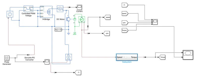
Here i have mentioned which block Names:
1. PWM Generator
2. Controlled Voltage Source
3. Controlled PWM Voltage
4. H-Bridge
5. DC-Motor(Permanant Magnet)
6. Ideal Rotational Sensor
7. Ideal Torque Sensor
8. Fan Speed and Toque Subsytem
9. Scope
PWM controlled fan load:
1. PWM Generator:
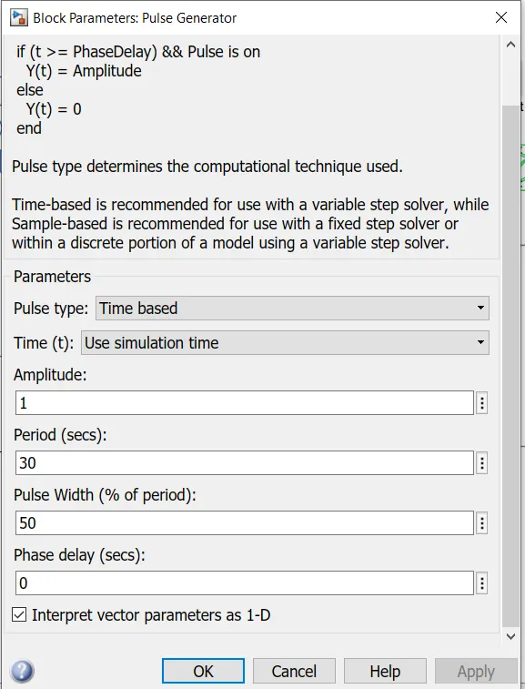
In pwm Generator input signals are Amplitude 1 and On and off peroid of 30 Sec and Duty cycle percentage is 50% feed into controlled voltage source.
2. Controlled PWM Voltage:
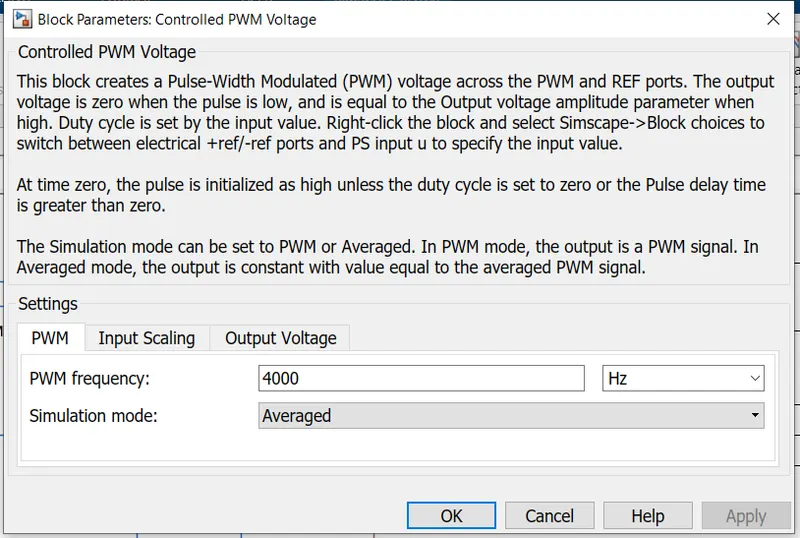
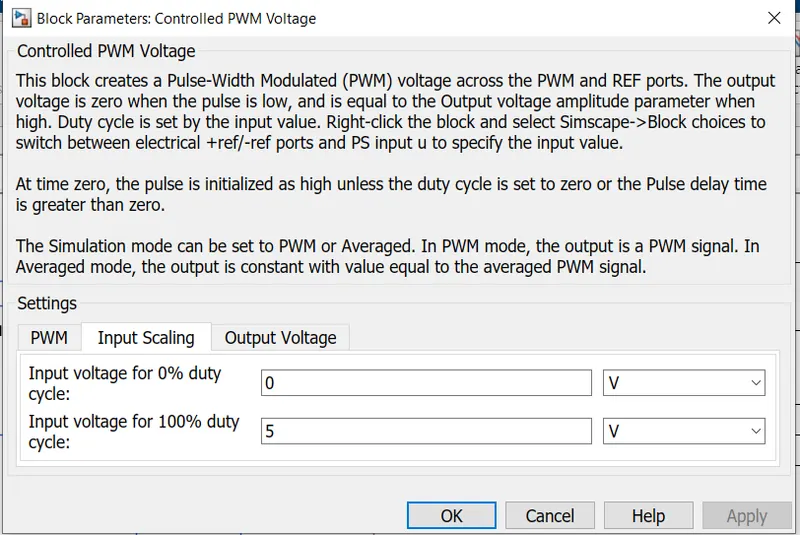
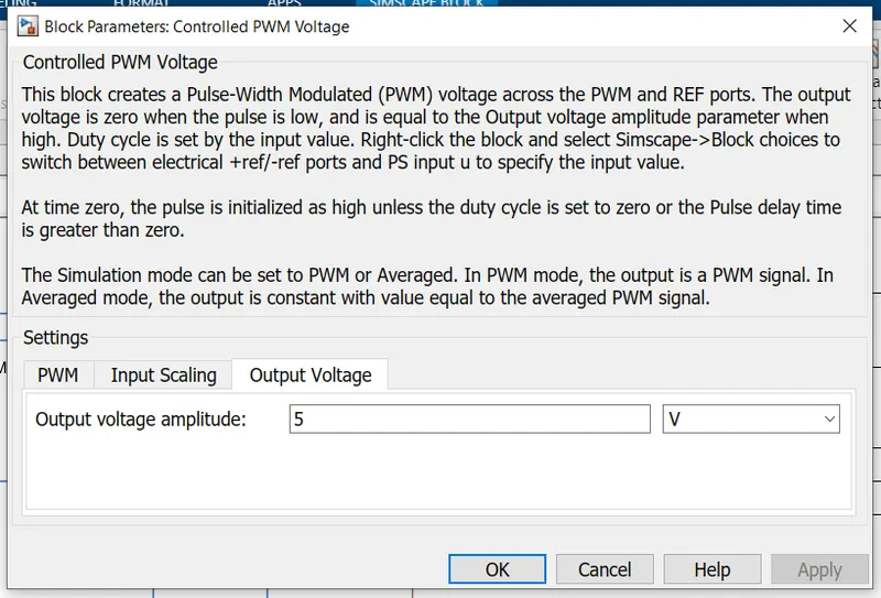
Getting input signal from controlled voltage source , The controlled pwm voltage is PWM voltage is 4000 HZ and Mode is averged mode and output voltage is 5V
3. H-Bridge:
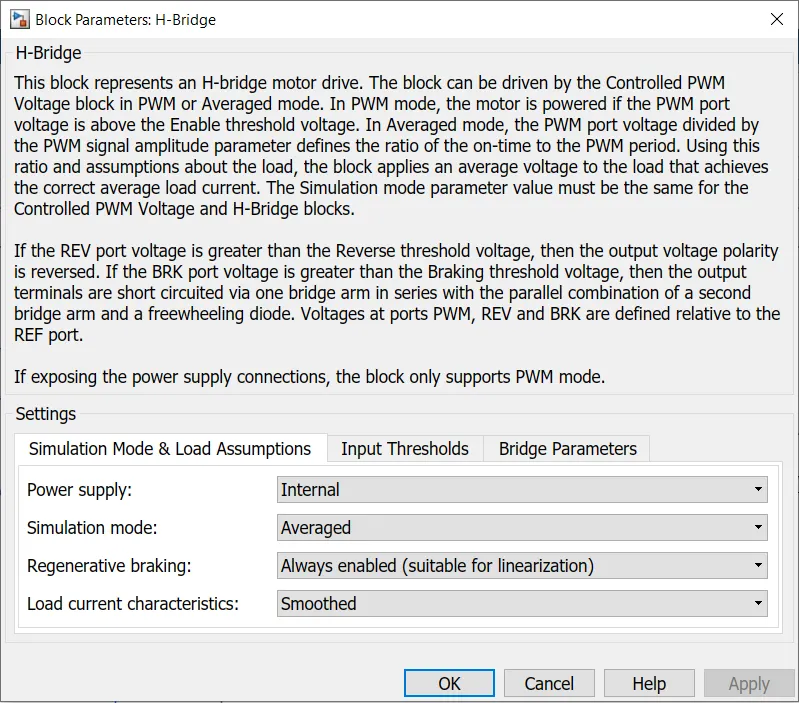
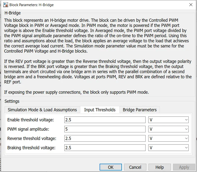
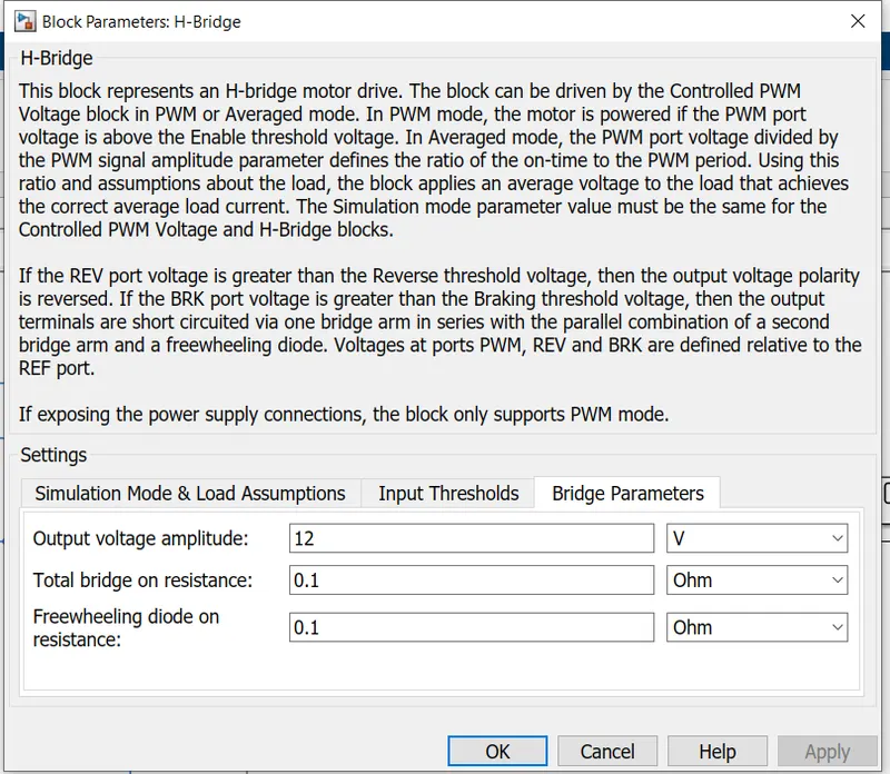
H-bridge circuit is used to controlled the dc motor with pwm signal in forward and reverse direction of motoring. here i have mentioned in H-bridge inputs
4. DC-Motor(Permanant Magnet):
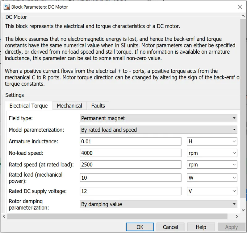
In dc motor permanent magnent and Rated speed and load speed are used, No load speed should be higher than rated speed. here i have mentioned the details.
5. Fan load Torque:
Torque is directly prportional to the speed square
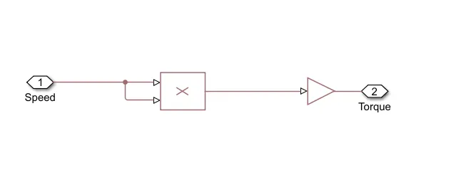
Formula is N*m/(rad/s)^2
PWM controlled fan load with DC motor Simulink Model:
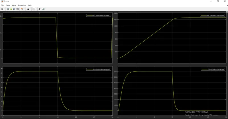
Results:
Total duration time is 30 Sec and Amplitude is 1 and Duty ccyle is 50%
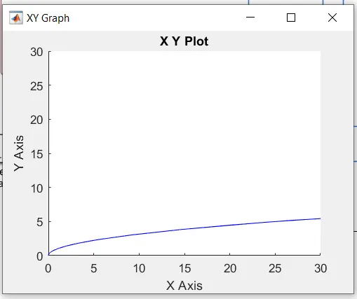
XY Graph:
X axis Torque and Y axis is Speed (Torque Vs Speed) of DC motor and fan
Here i have attached Simulink model