Project 1
Aim:Design and Develop a PWM controlled fan load with DC motor
Objective:
- System level congiguaration
- model parameters
- Result
- conclution
Introduction:This model shows how to use the Controlled PWM Voltage and H-Bridge blocks to control a motor
Block used:
- Pulse generator
- Controlled voltage source
- H bridge
- Current sensor
- DC motor
- Ideal rotational motion sensor
- Ideal Torque source
- Voltage sensor
PULSE GENERATOR:

This block generate pulses with respect to design
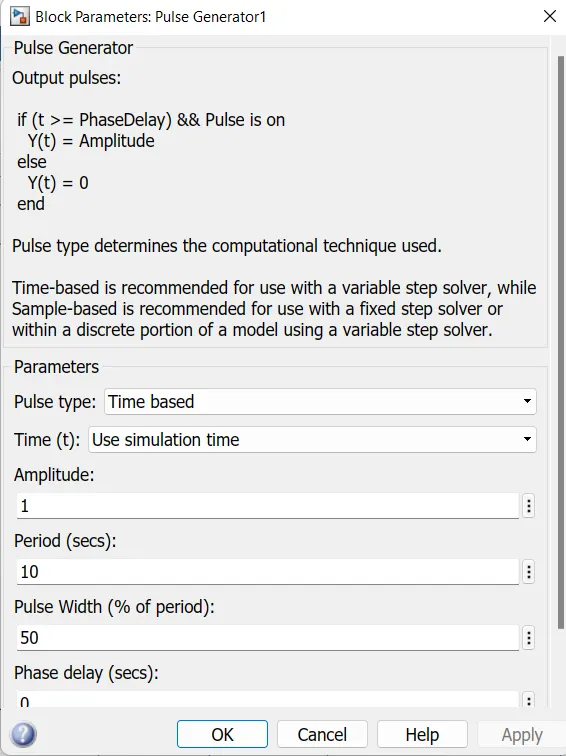
design:Pulse amplitude is set to 10 and pulse width set to 50%
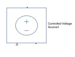
CONTROLLED VOLTAGE SOURCE:
H BRIDGE:
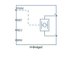
The H-Bridge block represents an H-bridge motor driver. The block has the following two Simulation mode options:
PWM — The H-Bridge block output is a controlled voltage that depends on the input signal at the PWM port. If the input signal has a value greater than the Enable threshold voltage parameter value, the H-Bridge block output is on and has a value equal to the value of the Output voltage amplitude parameter. If it has a value less than the Enable threshold voltage parameter value, the block maintains the load circuit using one of the following three Freewheeling mode options:
- Via one semiconductor switch and one freewheeling diode
- Via two freewheeling diodes
- Via two semiconductor switches and one freewheeling diode
The first and third options are sometimes referred to as synchronous operation.
The signal at the REV port determines the polarity of the output. If the value of the signal at the REV port is less than the value of the Reverse threshold voltage parameter, the output has positive polarity; otherwise, it has negative polarity.
Averaged — This mode has two Load current characteristics options:
- Smoothed
- Unsmoothed or discontinuous
The Smoothed option assumes that the current is practically continuous due to load inductance. In this case, the H-Bridge block output is:
(VO*VPWM/APWM)−IOUT*RON
where:
VO is the value of the Output voltage amplitude parameter.
VPWM is the value of the voltage at the PWM port.
APWM is the value of the PWM signal amplitude parameter.
IOUT is the value of the output current.
RON is the Bridge on resistance parameter.
The current will be smooth if the PWM frequency is large enough. Synchronous operation where freewheeling is via a bridge arm back to the supply also helps smooth the current. For cases where the current is not smooth, or possibly discontinuous (that is, it goes to zero between PWM cycles), use the Unsmoothed or discontinuous option. For this option, you must also provide values for the Total load series resistance, Total load series inductance, and PWM frequency. During simulation, the block uses these values to calculate a more accurate value for H-bridge output voltage that achieves the same average current as would be present if simulating in PWM mode.
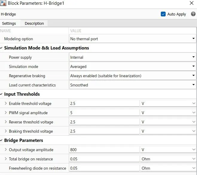
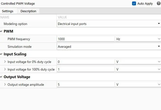
Design: For this model we selected power supply internal and simulation mode set to averaged and enabled regeneration braking ,we select smoothed load current charactesristics.All other values are set to default,we set the Simulation mode parameter to Averaged to speed up simulations and this applies the average of the demanded PWM voltage to the motor.
CONTROLLED PWM VOLTAGE:
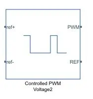
The Controlled PWM Voltage block represents a pulse-width modulated (PWM) voltage source. You can model electrical or physical signal input ports by setting the Modeling option parameter to either:
Electrical input ports — The block calculates the duty cycle based on the reference voltage across its ref+ and ref- ports. This option is the default.
PS input — Specify the duty cycle value directly by using an input physical signal port.
If you set Modeling option to Electrical input ports, the demanded duty cycle is
100∗Vref−Vmin/Vmax−Vminpercent
where:
Vref is the reference voltage across the ref+ and ref- ports.
Vmin is the minimum reference voltage.
Vmax is the maximum reference voltage.
The value of the Output voltage amplitude parameter determines amplitude of the output voltage.At time zero, the pulse is initialized as high, unless the Pulse delay time parameter is greater than zero, or the demanded duty cycle is zero.You can use parameters Pulse delay time and Pulse width offset to add a small turn-on delay and a small turn-off advance. This can be useful when fine-tuning switching times so as to minimize switching losses.In PWM mode, the block has two options for the type of switching event when moving between output high and output low states:Asynchronous – Best for variable-step solvers — Asynchronous events are better suited to variable step solvers, because they require fewer simulation steps for the same level of accuracy. In asynchronous mode the PWM switching events generate zero crossings, and therefore switching times are always determined accurately, regardless of the simulation maximum step size.Discrete—time – Best for fixed-step solvers — Discrete-time events are better suited to fixed-step operation, because then the switching events are always synchronized with the simulation step. Using an asynchronous implementation with fixed-step solvers may sometimes result in events being up to one simulation step late. For more information, see Simulating with Fixed Time Step — Local and Global Fixed-Step Solvers.
CURRENT SENSOR:
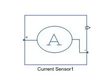
The Current Sensor block represents an ideal current sensor, that is, a device that converts current measured in any electrical branch into a physical signal proportional to the current.
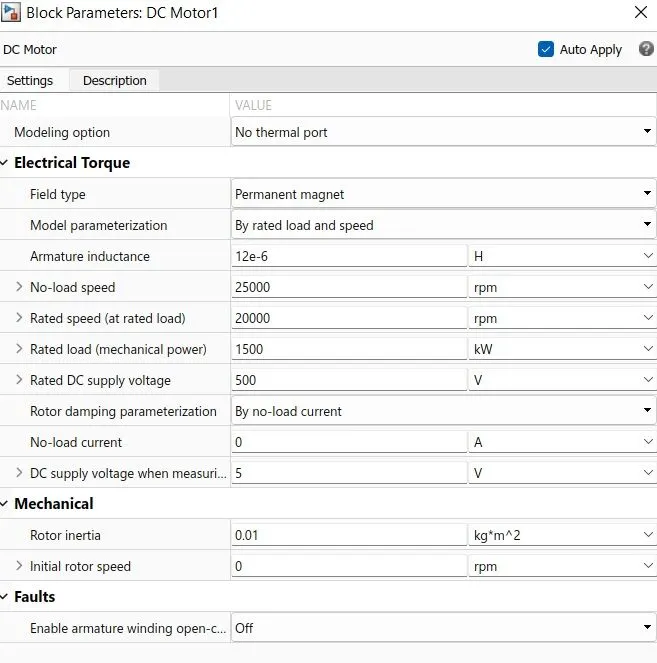
DC MOTOR:
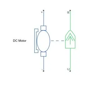
The DC Motor block represents the electrical and torque characteristics of a DC motor using the following equivalent circuit model:
You specify the equivalent circuit parameters for this model when you set the Model parameterization parameter to By equivalent circuit parameters. The resistor R corresponds to the resistance you specify in the Armature resistance parameter. The inductor L corresponds to the inductance you specify in the Armature inductance parameter.
You can specify how to generate the magnetic field of the DC motor by setting the Field type parameter to the desired option. The permanent magnets in the motor induce the following back emf vb in the armature:
vb=kvω
where kv is the Back-emf constant and ω is the angular velocity. The motor produces the following torque, which is proportional to the motor current i:
TE=kti
where kt is the Torque constant. The DC Motor block assumes that there are no electromagnetic losses. This means that mechanical power is equal to the electrical power dissipated by the back emf in the armature. Equating these two terms gives:
TEω=vbi
ktiω=kvωi
kv=kt
As a result, you specify either kv or kt in the block parameters.
If the magnetic field is generated from the current flowing through the windings, the Back-emf constant depends on the field current If:
kv=LafIf
where Laf is the Field-armature mutual inductance.
The torque-speed characteristic for the DC Motor block is related to the parameters in the preceding figure. When you set the Model parameterization parameter to By stall torque & no-load speed or By rated power, rated speed & no-load speed, the block solves for the equivalent circuit parameters as follows:
For the steady-state torque-speed relationship, L has no effect.
Sum the voltages around the loop and rearrange for i:
i=(V−vb)/R=V−kvω/R
Substitute this value of i into the equation for torque:
TE=(kt/R)*(V−kvω)
When you set the Model parameterization parameter to By stall torque & no-load speed, the block uses the stall torque and no-load speed to determine values for R and kt (and equivalently kv).
When you set the Model parameterization parameter to By rated power, rated speed & no-load speed, the block uses the rated speed and power to calculate the rated torque. The block uses the rated torque and no-load speed values to determine values for R and kt.
The block models motor inertia J and damping λ for all values of the Model parameterization parameter. The resulting torque across the block is:
T=kt/R*(V−kvω)−J˙ω−λω
It is not always possible to measure rotor damping, and rotor damping is not always provided on a manufacturer datasheet. An alternative is to use the no-load current to infer a value for rotor damping.
For no-load, the electrically-generated mechanical torque must equal the rotor damping torque:
ktinoload=λωnoload
where inoload is the no-load current. If you select By no-load current for the Rotor damping parameterization parameter, then this equation is used in addition to the torque-speed equation to determine values for λ and the other equation coefficients.
The value for rotor damping, whether specified directly or in terms of no-load current, is taken into account when determining equivalent circuit parameters for Model parameterization options By stall torque and no-load speed and By rated power, rated speed and no-load speed.
When a positive current flows from the electrical + to - ports, a positive torque acts from the mechanical C to R ports.
Design: Here we set permanent magnet type dc motor it is parameterized by rated load and speed and we set no lod speed 25000 and rated speed=20000rpm ,rated load value set to 1500kW and rated dc supply voltage is set to 500V and all other parameter value kept default
MECHANICAL ROTATIONAL RESISTANCE:
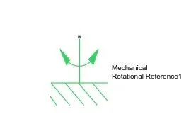
This block represents a mechanical rotational reference point, that is, a frame or a ground. Use it to connect mechanical rotational ports that are rigidly affixed to the frame (ground).This is actually a mechanical system block
ELECTRICAL REFERENCE
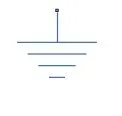
The Electrical Reference block represents an electrical ground. Electrical conserving ports of all the blocks that are directly connected to ground must be connected to an Electrical Reference block. A model with electrical elements must contain at least one Electrical Reference block.
INERTIA
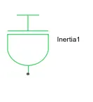
The block has one or two mechanical rotational conserving ports. The difference is purely graphical, as the ports are rigidly linked. The block positive direction is from its port to the reference point. This means that the inertia torque is positive if the inertia is accelerated in the positive direction.
Design:value set to0.01 kg*m^2
IDEAL TORQUE SOURCE
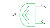
The block represents an ideal source of torque that generates torque at its terminals proportional to the input physical signal. The source is ideal in a sense that it is assumed to be powerful enough to maintain specified torque regardless of the angular velocity at source terminals.
Design:this block is given for aerodynamic drag
IDEAL ROTATIONAL MOTION SENSOR
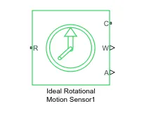
Ideal motion sensor is provide here to sense the rotational speed of the motor
SQUARE LAW SUBSYSTEM:
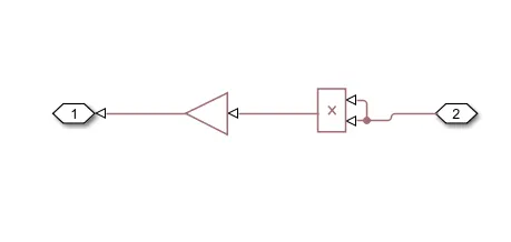
Here Torque is calculated from speed.
we know Torque=Kw^2
here we gave the gain value=-8e-8 Nm/(rad/s)^2
All the block are connected as shown above and run the simulation for 50s
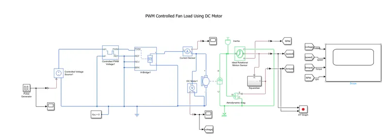
Working:
The signal from the pulse generator is given to physically controlled voltage source,It produces voltage output according to the physical signal input,these output are also varies between zero to 1The output of controlled voltage source1 goes to controlled PWM .It give output according to input signalsThese output values is fed to a H bridge If the input signal has a value greater than the Enable threshold voltage parameter value 2.5V the H-Bridge block output is on and has a value equal to the value of the Output voltage amplitude 800V. If it has a value less than the Enable threshold voltage parameter value, the block maintains the load circuit using freewheeling diode.The Output of H bridge is connected to dc motor the motor rotates according to the voltage output fom h bridge.This speed of the motor is sensed by ideal rotational motion sensor and taken as output ,by using square law Torque also calculated.
Results:
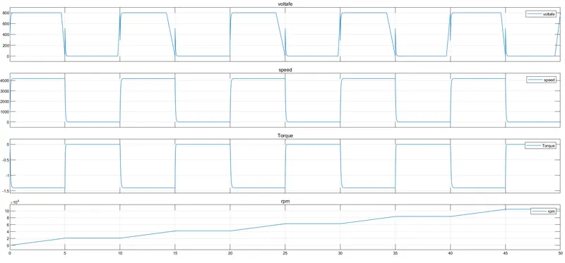
Observarion:
- Voltage of the motor varries respect to input from pulse generator
- RPM value increases with increasing time
- We can see torque value is inversely proportional to speed
Output of XY graph
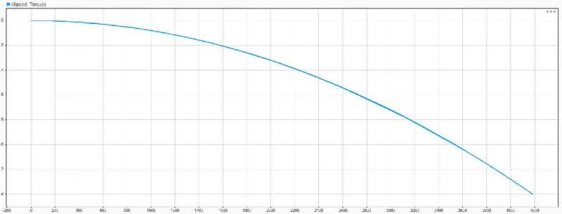
- speed and torque input given to xy graph,and ploted speed torque curve ,torque varies inversely with speed
Conclusion:Simulation of PWM controlled dc motor fan load is done and Output are observed.