Project 1
PROJECT 1
Statement of assignment:
Route the Wiring harness on Given Engine and Prepare flattened view drawing in CATIA V5. Application of all Packaging rules, Industry best practices studied in this course shall be demonstrated in design. Apply Protection coverings as required.
Prepare & Submit all necessary reports like clearance, Clipping/Clamping selection, Harness fixing requirements, Harness continuity.
--> Engine Wiring Harness Routing
Constricted wires, cables, terminals, and connectors that control an automobile's electrical system make up an engine wiring harness. It transmits control information and electrical power to many components, including computers, blower motors, batteries, alternators, fuel injectors, fuses, and audio systems. Wire harness manufacturers adapt it to each location, use case, and design it integrates with. Often referred to as a cable harness, it is more than just a grouping of connected wires.
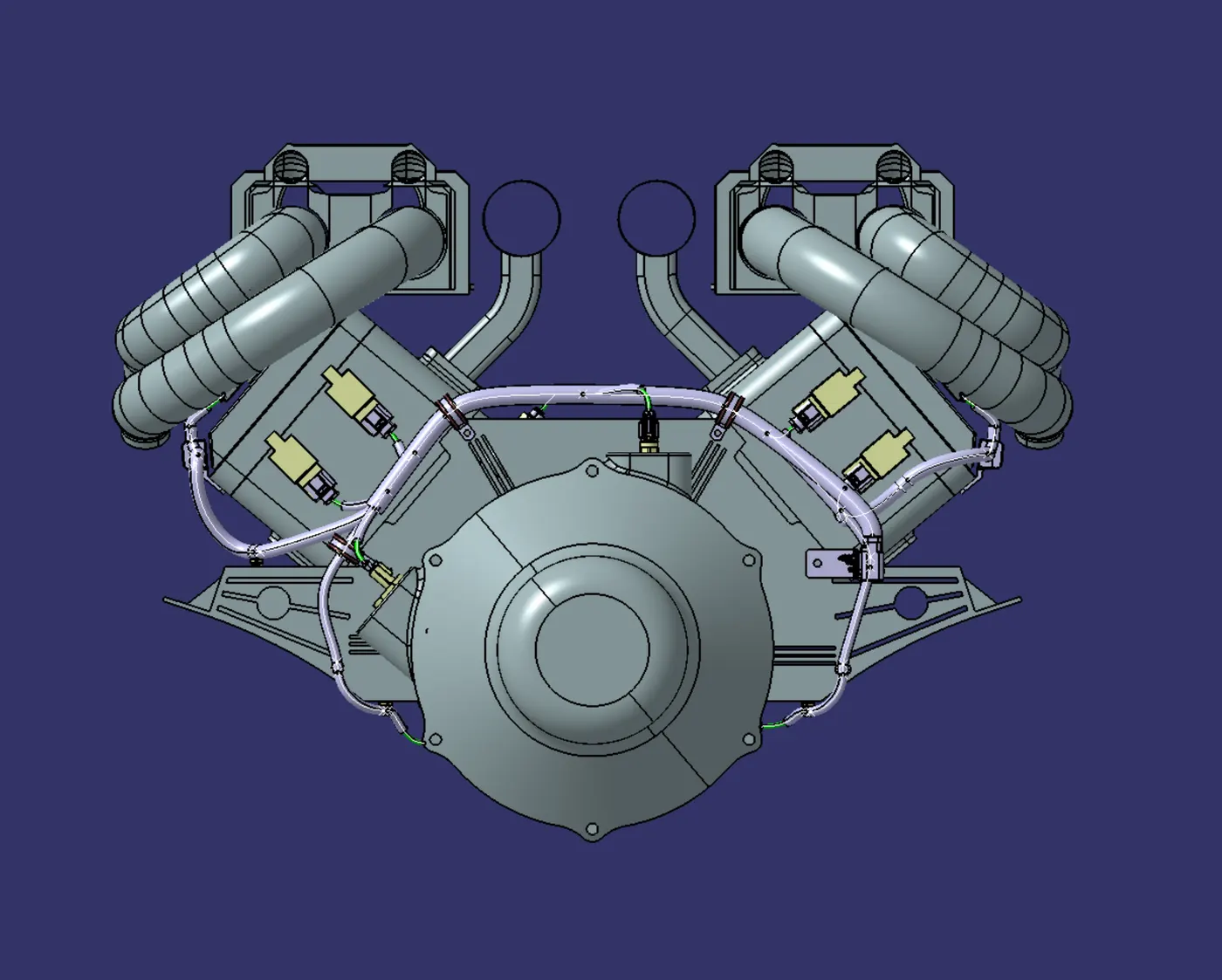
The wire harness is routed by taking the engine out. The dummy connectors will be supplied at each position by the engine .
First, make sure every sensor and connector is in its proper place. The current engine features two sensors and eight connecting locations on each side.
The harness can be routed with the best possible outcome by using the channels, clamps, and clips.
There are a total of 20 sensors that need to be electrically linked, including 4 cam-shaft sensors.
Typically, 4-pole connectors are utilized for the engine's fuel injectors.
Additionally, an interface connector built within the engine will allow it to be connected to other components of the car. As an interconnection connector, we'll be using a 12-pole electrical connector with a mounting clip feature.
This harness's plastic guiding channel needs to be constructed from a material that can tolerate temperatures of at least 150 degrees Celsius.
Every bundle segment should have a bend ratio of 1.4.
As needed, supply clamps or clips.
When constructing the wire harness, make sure there are no failure cases. It is possible to prevent failing cases by using extra clips or clamps.
Let more leeway if necessary. A gap of 5–10% is adequate.
To prevent puncturing the harness, avoid routing across bolts and fastened joints.
If you must route near jagged edges, cover the harness with protection.
Observe the clearance distance and keep the harness away from any parts that produce heat.
The appropriate level of protection should be given based on the ambient temperature.
Steer clear of supporting the harness directly on the engine's fuel lines.
If necessary, use plastic guiding channels.
A branch's length shouldn't exceed 50 millimeters.
There should be a minimum of 50mm between two branch locations.
A minimum of 25mm should elapse between the clip and the branch point.
Don't overload the engine with sheet metal brackets. Try to use the engine's available threaded bosses or make a request for them.
It should be simple to access and construct the wiring harness.
Make sure the positions you are specifying with dummy connectors are realistic. For the wire harness routing, bundle sizes and other placements can be appropriately defined.
We can consider building a harness channel, which can be utilized to efficiently route and protect the wire harness, if the packing area is too small and there are numerous packaging restrictions.
--> ELECTRICALLY DEFINED PARTS
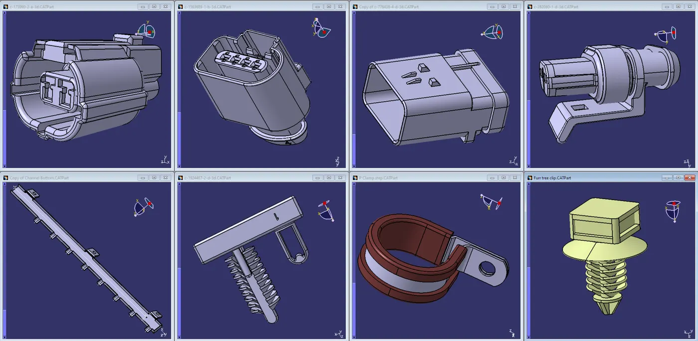
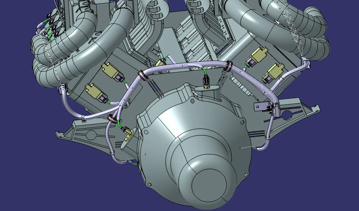
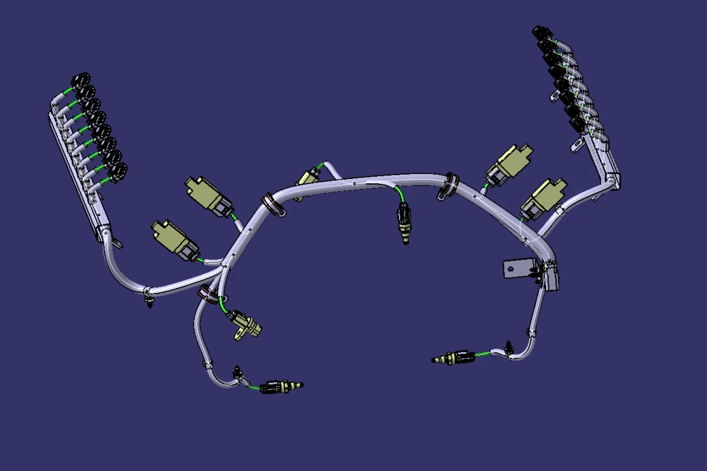
The assembly's connectors should be electrically defined, and it should be mounted on the engine surface in the proper location.To achieve the correct routing without the bundle getting in the way of the surrounding components, insert the supporting mounting clips in the engine after the connectors have been positioned.Once this path has been achieved, ensure that the bundle segments do not collide with the surrounding areas of the geometric bundle.Once the geometric bundle has been finalized, flatten it and check that the wire harness has the bundle connected properly.
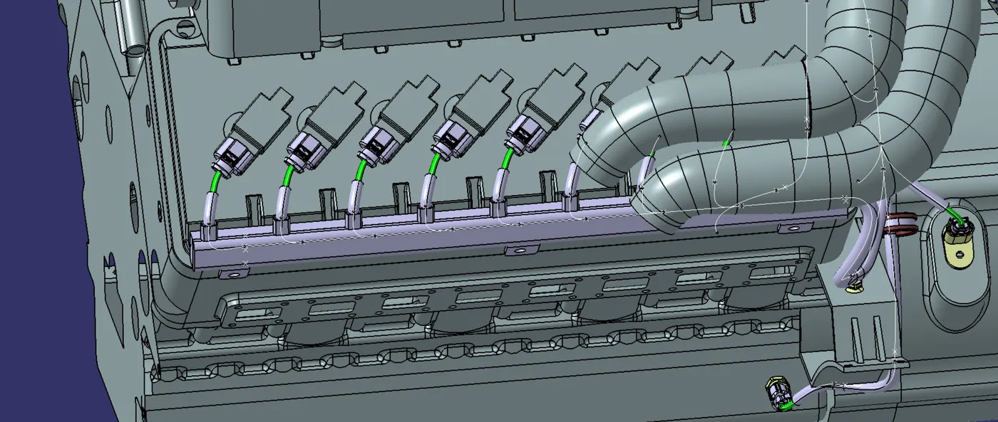
Connectors to cam-shaft sensors and fuel injector sensors are being installed. Therefore, we will need to add a total of 20 connectors to the Engine Harness Geometrical Bundle Assembly. In order to place all 20 connectors in the appropriate areas, we must employ manipulation tools in addition to compass, snap, and smart move functions.
--> BUNDLE CONTINUITY
--> FLATTENING
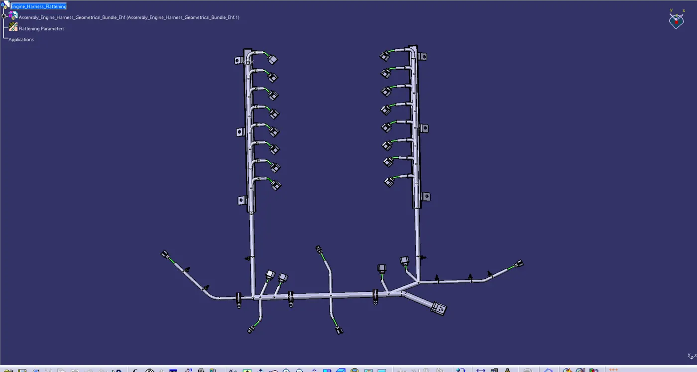
In this stage, it's necessary to work in the Catia V5 Electrical Harness Flattening workbench in order to create the flatten view. Additionally, we need to confirm that the flattening file is stored in the same folder as the other harness assembly files.
We must first define the flattening settings before we can create the flatten view. Ensure that the "Double" line is selected for the protective covering and the "Single line" for the bundle segment.
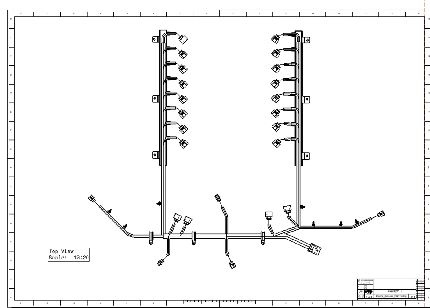
The bundle assembly was extracted into the Engine Harness Flattening Product file, and as the above graphic illustrates, the file was then flattened along the interconnection connector's face.
For the purpose of clarity, the flattening diagram of the plastic guiding channels has been hidden from the drawing view at this point.
We are creating a new drawing file and defining all required drawing parameters in the above figure. The Engine Harness Flattening Product file's front view needs to be inserted into the Drawing file.