Project 1
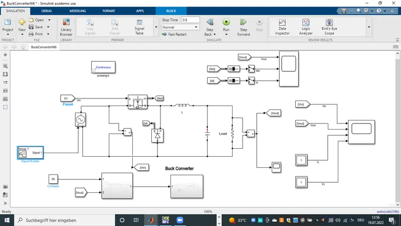
1) The first model to be developed is the Buck converter.
-it has input voltage ranging from 40 to 50 V, output volage is 30V with a power of 500W.
The model is as shown below.
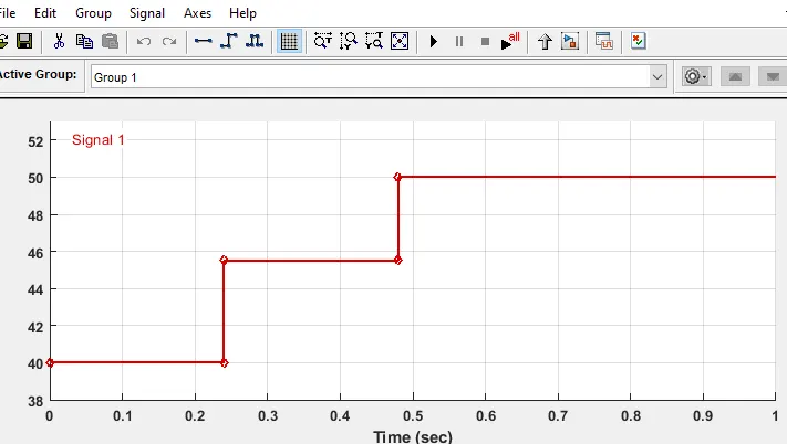
-Using the signal builder and control voltage source block, a varing voltage input is given as shown below.
The various electrical components were sized as follow.
Input Voltage is 40-50V
Output voltage 30V
Power = 500W
-Output resistor = `(Vout^2)/(P)` = ` 30^2/500 = 1.8 oms
-This gives us an output current of 30V/1,8ohms = 16.6A
-since Duty ratio D is needed tzo calculate L and C
-Duty ratio D = Vout/Vin = 30/45 = 0.75
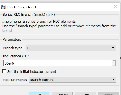
-L is `(Vout*(1-D))/(fo*triangleIl)`
with a currnt ripple of 20%, and subtituting the above values we get a value of 36uH
-C capacitor is calculated as follow.
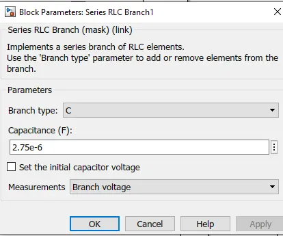
`(triangle IL)/(8*fs*triangleVout)`
-with a 5% voltage ripple delta V = 1.5V
-substituting in the above formular = 2.7uF
Compensation block:
the output voltage is compared with the output reference 30V and passed to a PID block and the difference is used to adjust the PWM of the mosfet to constantly maintain the output at 30V
Simulation and Results.
-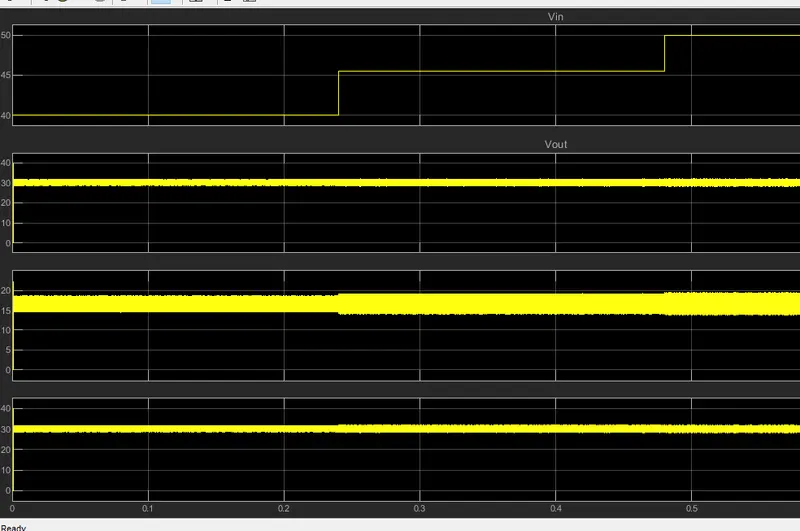
-The first plot shows the varing input voltage from 40V to 50V
-The output voltage is controled to the stady 30V output.
-while our output current is somewhere around 17A
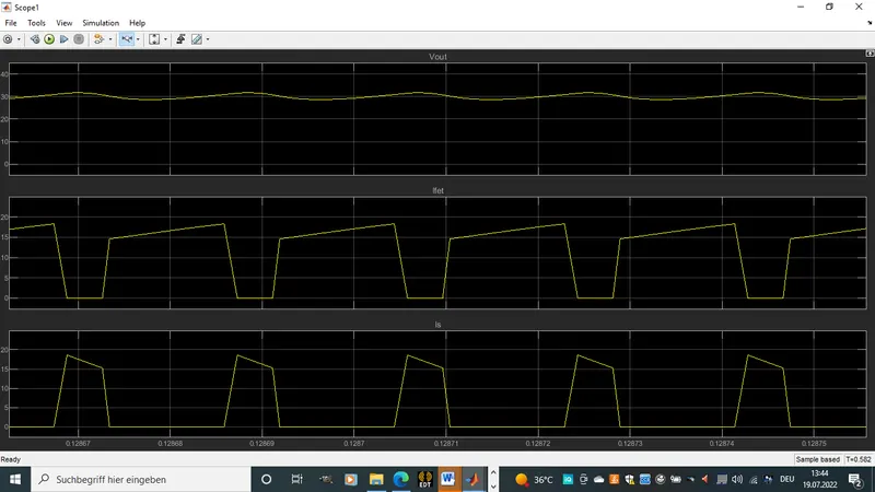
In this picture we can see clearly the current across the switch and diode. this shows clearly that both never work at the same time. when fet is closed current dose not pass through the diode and vise versa.
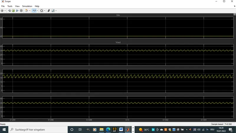
-The 2 last images show us the inductor current and the capacitor voltage. it is visible that the inductor current has more ripples as compared to the capacitor voltage. This is because i designed the circuit to have 20% ripple and the capacitor voltage just 5% ripple
2) The second is the boost converter at CCM mode.
-The circuit has a varing input voltage of 20 to 30V producing and output statdy voltage of 40V and 600W.
-The model is build as show below.
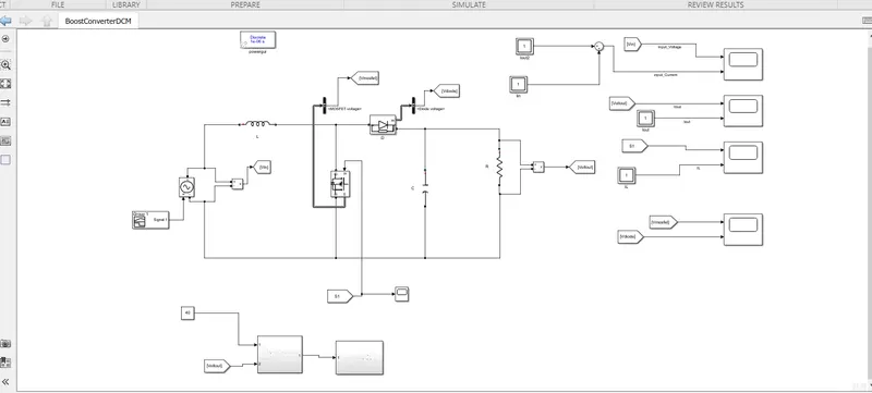
-In the CCM mode the inductor current never gets to zero.
-Input voltage is 20 to 30V
-Output voltage is 40V
-power is 600W.
-Hence resistance R is 40^2 / 600W . This gives us and output load resistance of 2.6 ohms
-Output current is 40V/2.6ohms which gives 15.3A
-To calculate the circuit duty cyclec, D = `1- (V i n)/(Vout)`
-This gives a D = 0.37
-L is calculated as `(V i n*D)/(fs* triangleIL)`
-with a 20% ripple for inductor current the `triangle Il =` 3A
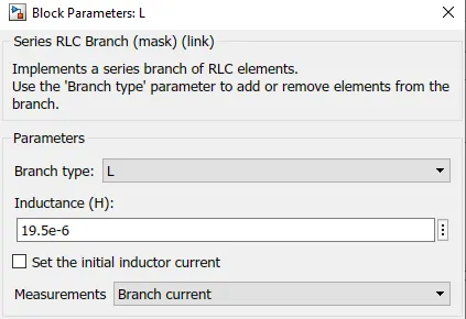
-Hence this gives us and inductor value of 19.5uH as show below
-The capacitor of the circuit is calculates as follow.
C = `(Vout)/(triangle Vout*R*fs)`
-I will like my output voltage to have lower ripples hence a ripple of 5% is choosen.
-This gives a `triangleVout =` 40 * 0.05 = 2V
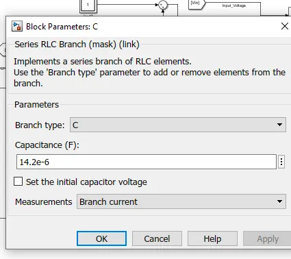
-Hence giving a capacitor value of 14.2uF as shown below.
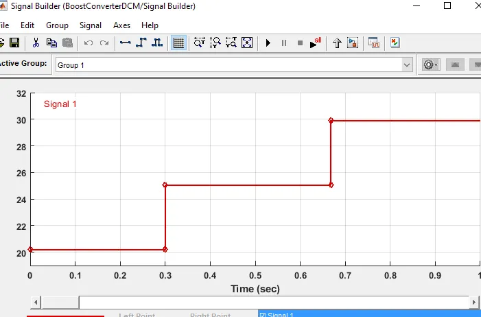
The input signal is varried with the help of a signal builder and a control voltage source
Simulation and results:
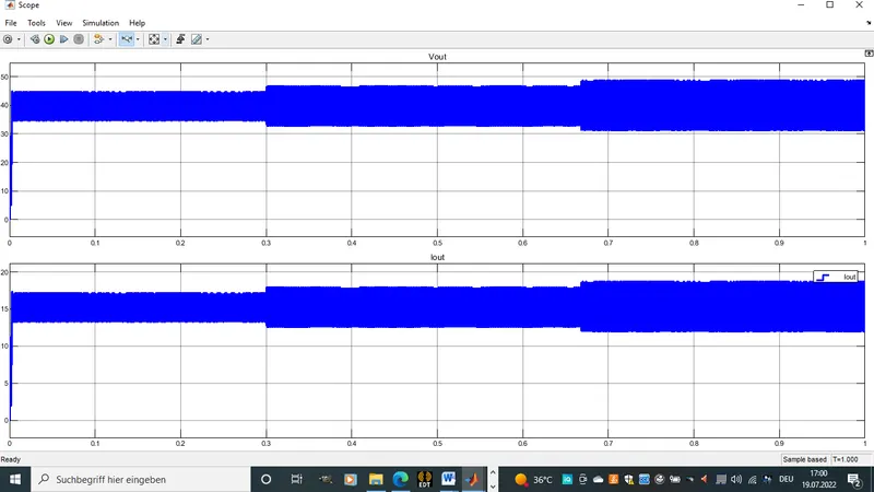
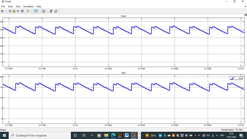
We observe that the output voltage is controled at 40V dispite the change at the input voltage.
-Also the ripple of the current and voltage are to be seen as calculated.
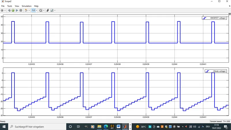
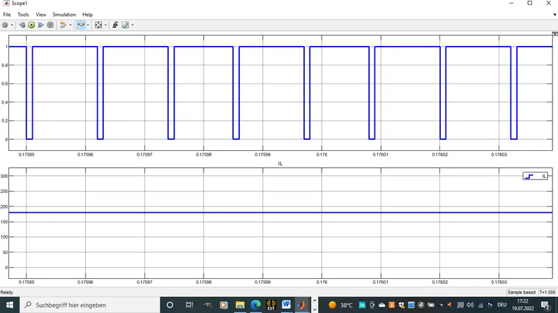
-Here we see the voltage across the mosfet and the diode. The PWM and the current Il. when the mosfet is conducting or when its switch is on, there is no voltage across and vise versa.
3)The third topologie is the SepicConverter with input voltage 30 to 60V and an output voltage of 45V with 1kW of power.
Th cicuit is modeled as shown below.
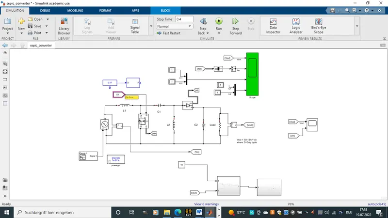
The input voltage is 30 to 60V
Output voltage is 45V with 1kW of pour.
-Output load resistor is voltage square divided by power = 2 ohms
-hence the output current is 45V / 2 ohms = 22.5A
-Before starting with the calculation all inductance current will be calculated with 20% ripple while all capacitance voltage will be calculated with 5% ripple.
-The Duty cycle D is calculated as shown below
`(Vout)/(V i n) = (D)/(1-D)`
hence D = `(Vout)/(Vout + Vi n)` = 0.47
-L2 is calculate using the below formular
`(Vout)/(R)*(D)/(1-D)` which gives us a value of 59uH as shown below.
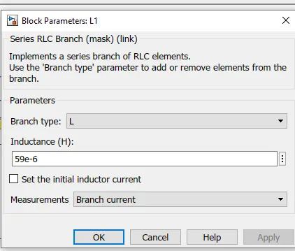
-Using the same forlmular for L1, L2 is calculated to have a value of 53uH
-C1 and C2 are given the same value using the below calculation
C1 = C2 = `(Vout * D)/(R * fs * triangleVout)`
This gives a value of 47uF
-The input volatge is varried as shown below.
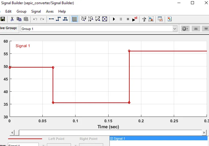
simulaTION and results:
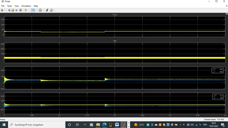
-The outputvoltage is controled at 45V despite change in input voltage.
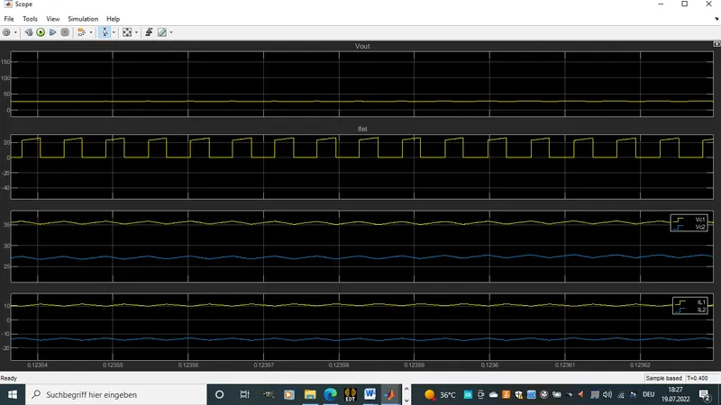
-The inductance current and capacitor voltage show ripples as calculated.
-The mosfet current shows how the switching conducts current across the switch.