Project 1
PROJECT 1- ENGINE WIRING HARNESS DESIGN
Aim: To Route the Wiring harness on Given Engine and Prepare flatten view drawing in CATIA V5. And to apply Protection coverings as required.
Connectors Used
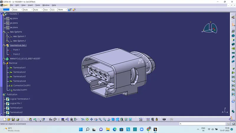
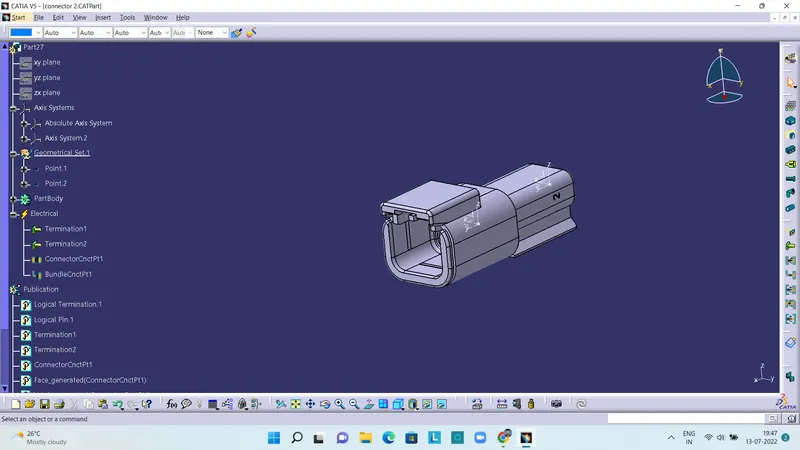
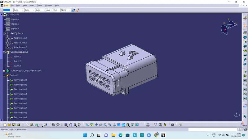
These are the connectors used for the harness design. For defining connector connection point and bundle connection point, points and axis systems are created. After that in electrical part design workbench, these are then defined as connectors. After that these are then added to connector catalogue.
Mounting Equipments Used:
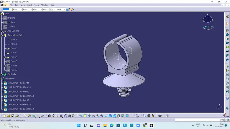
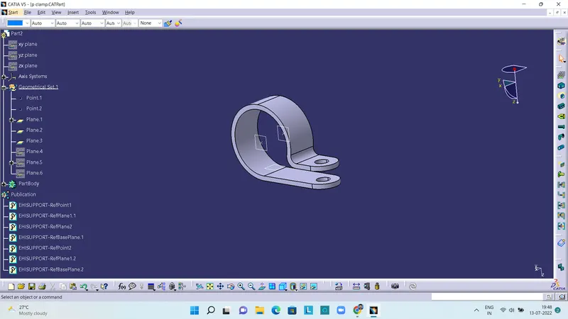
The above picture shows a Fir tree clip and a P-clamp. Here three planes and two points are created for bundle entry and exit. Then they are defined as support part.
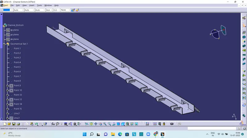
The above picture shows a channel for the bundle. For defining it as an equipment, points and line are created. The line is the guiding curve for the bundle.
Position of Connectors & Mounting Equipments
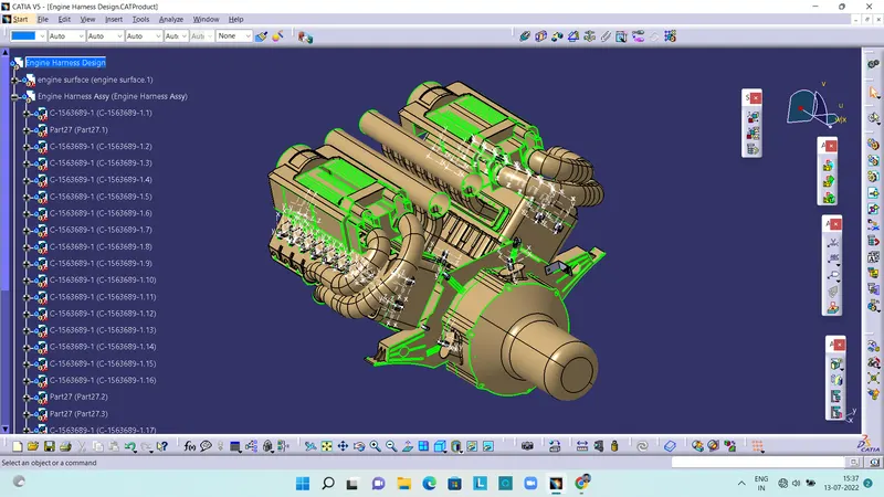
After defining the connectors and mounting equipments, they are then positioned on the engine. P-clamps and fir tree clip are positioned on the suitable position.
Bundle Creation
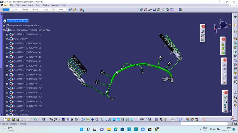
After the positioning the connectors and equipments, harness bundle is created accordingly for the connectors, through the mounting equipments.
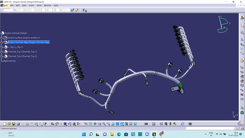
After the bundle creation, the harness is protected from the heating of engine with the help of corrugated tubes of 20mm and 10mm diameter.
Final Assembly
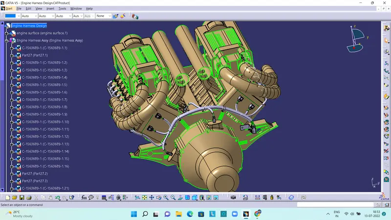
The above figure shows the final assembly of engine harness.
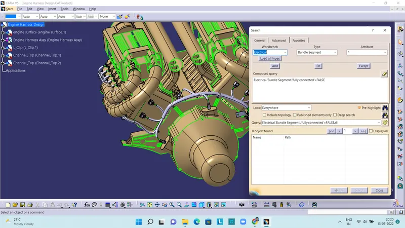
The above figure shows checking of Harness continuity using search command. There are 0 branches found which are not continuous. Therefore the design is practicable.
Connector catalogue, Corrugatted tubes catalogue, Part files and the assembly files are attached as .zip folder.