Project 1
Aim: To create a stateflow or simulink model for the following flowchart.
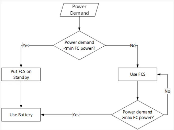
As shown in above flowchart, there are two power sources mention as fuel cell(FC) and battery.
The logic which is required in this is that if the power demand from the vehicle is less than the minimum FC power than the FC must go on standby and the power should be supplied from the battery storage system and if the power demand is greater than the min FC power than the FC should be used and if the power demand of vehicle is more than the max power of FC than the battery should supply the power.
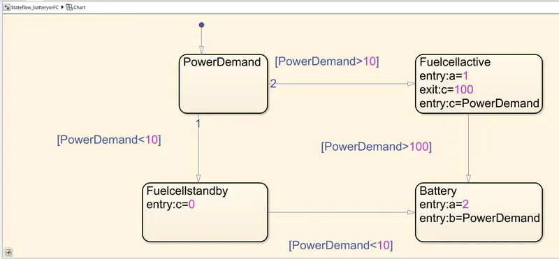
The state flow chart is been developed for this as shown below,
operating region of FC is 10 to 100
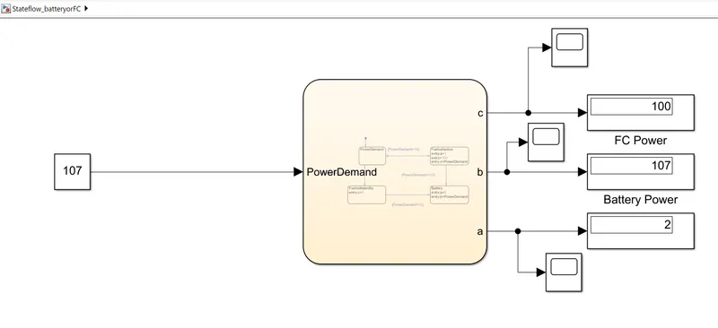
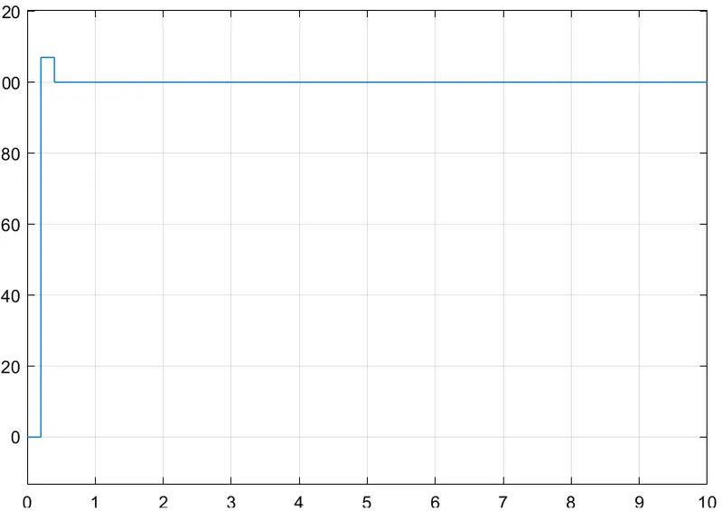
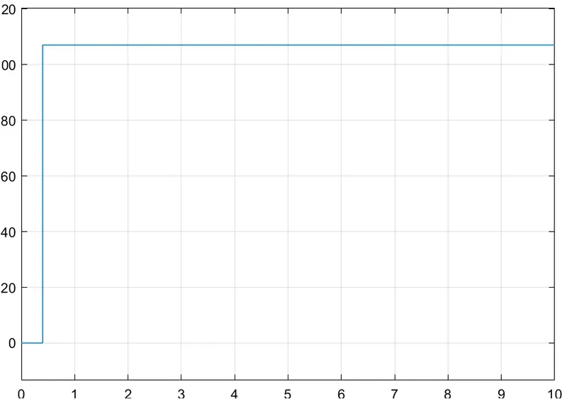
Constant block is used as the input to give the power demand required by the vehicle, the simulation is been run for 10 sec and the output such as FC power, battery power and FC status are been studied by connecting it to scope.
If we look inside the stateflow chart it is as shown below.
From the result it is clear that the logic which is been developed is full proof and working proper as per the logic defined.
For FC Power:
For battery power:
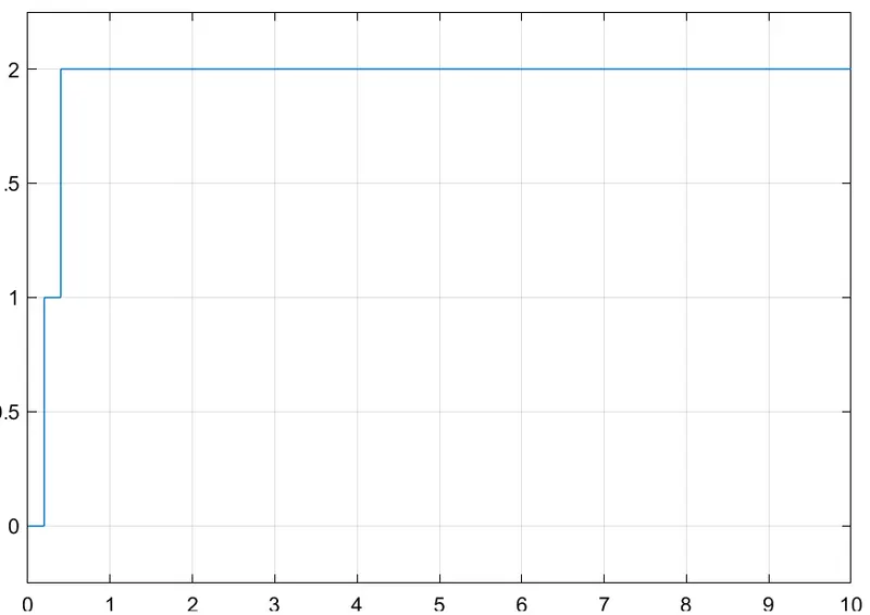
Selection of battery or FC(Here 1 is for FC and 2 is for battery)