Project 1
FINAL PROJECT CAD CHALLENGE
For this project, a CAD file of a 16-cylinder engine was provided.
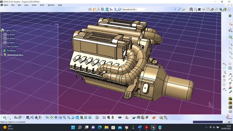
Certain tasks were performed before routing the wire harness which includes:
- harness assembly components were identified
- CAD files of components such as clips, and connectors, were downloaded from a third-party website, TE
- the CAD files were electrically defined
- harness assembly was defined and the components were placed in appropriate locations
- the assembly was electrically defined
- certain parameters and tools settings were changed
- routing of the bundles considering some management such as thermal management
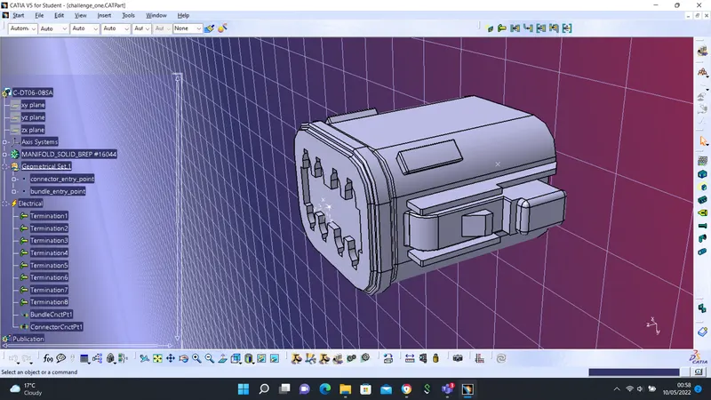
step 1 - CONNECTORS DEFINITION
Some of the components used such as connectors were electrically defined. The process includes:
- CAD files downloaded
- geometrical parameters created
- part defined as a connector
- connector bundle point defined
- connection connector point defined
Sample Connector Definition
Step 2 - PLACING COMPONENTS
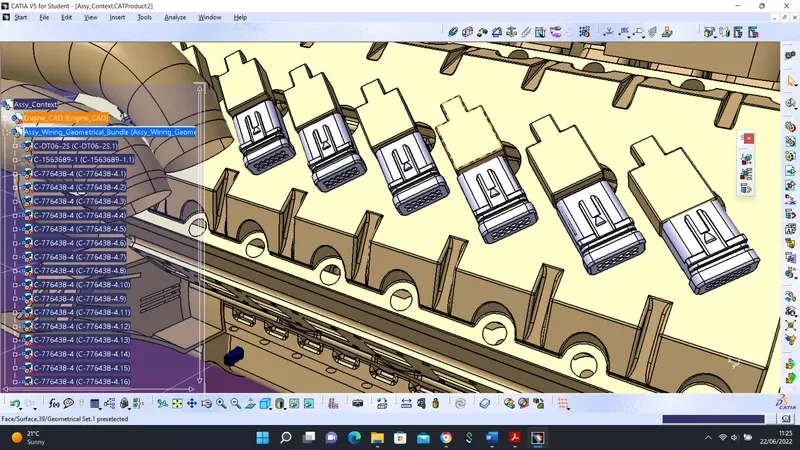
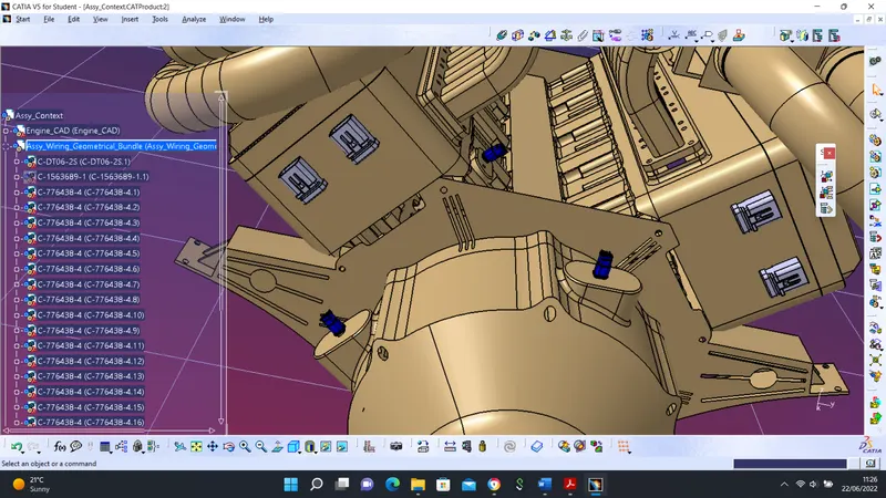
After the components were electrically defined, the components such as connectors, clips, and clamps, were all placed at appropriate locations on the engine.
Sample Connectors Placement
Step 3 - HARNESS ROUTING
Following some routing rules and standards. Certain geometrical bundle warnings were resolved by adding slack to the harness.
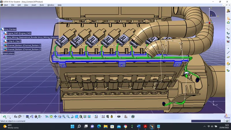
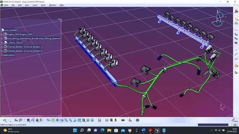
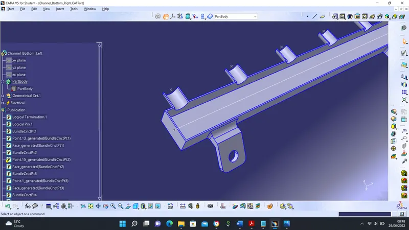
Routing with external curve
This operation allows routing to be done around curves. The image below shows routing performed on a channel.
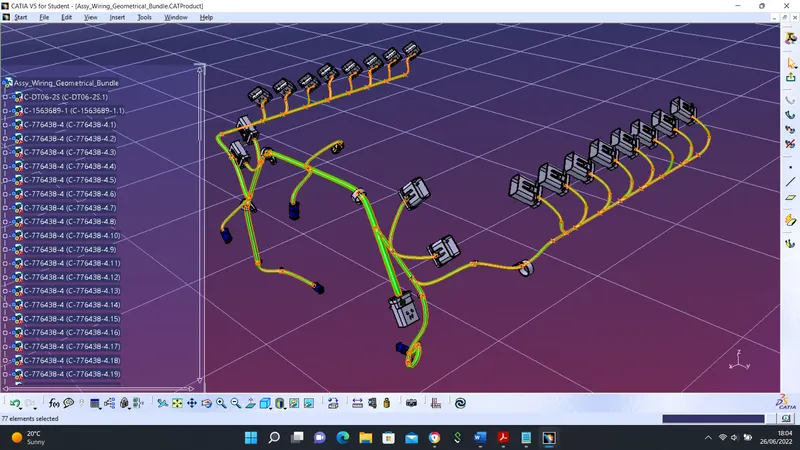
Step 4 - CONNECTIVITY CHECK
Certain operations were performed to check if the bundles are fully connected. The orange coloration indicates full connectivity.
THERMAL MANAGEMENT
Routing management is vital, especially in high-temperature zones like the engine zones. In ideal situations, Thermal Mapping Data of the vehicle is needed to route the harness. Some of the practices used include:
- Corrugated tubes
- Chaffing protection
Corrugated Tubes
Flattening