Project 1
1. Defining all connecters
STEPS FOR HARNESS ROUTING.
- Next step is defining all the connectors and Bundles in Electrical Part Design [EPD] using points and Axis for connector.
- Generate branches according to the dimensions given in the question and save it as CATPart.
- Import Branch file into the product file in Electrical Assembly Design [EAD].
- Use Snap option from Move Toolbar available in the Assembly Design Workbench [general] to align the components according to the question.
- Use compass to define the orientation of the components according to the diagram given in the question.
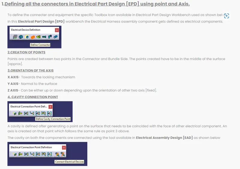
DEFINING THE COMPONENT AS CONNECTOR IN ELECTRICAL PART WORKBENCH [EPD]
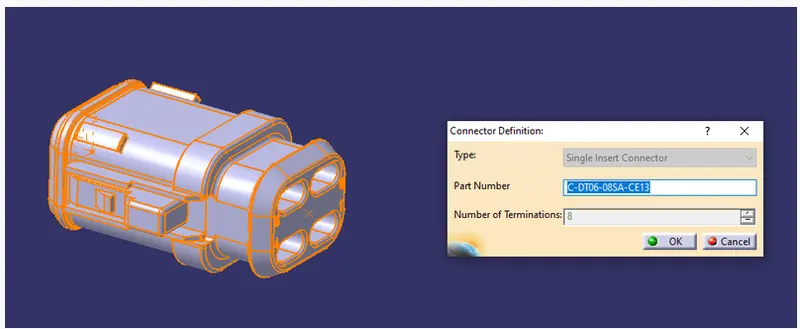
GENERATION OF POINTS ON BUNDLE AND CONNECTION SIDE
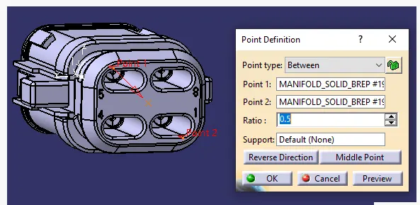
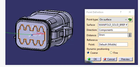
DEFINING THE CONNECTING CONNECTION AND BUNDLE CONNECTION POINT IN EPD
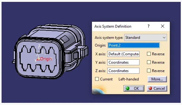
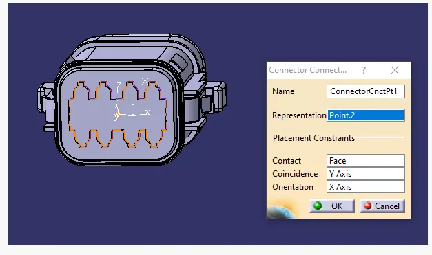
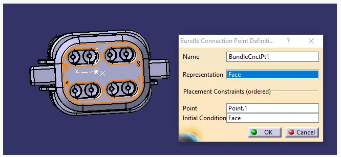
Defining the Cavity and Generating the Axis
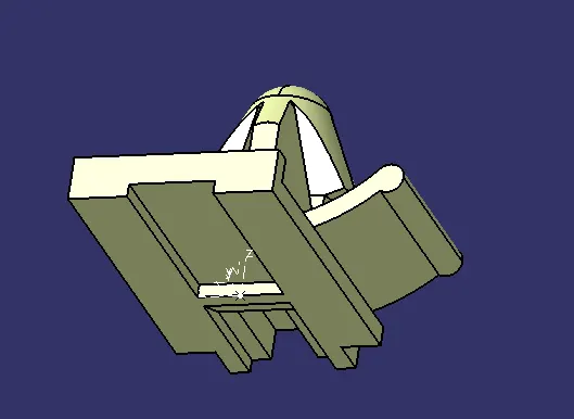
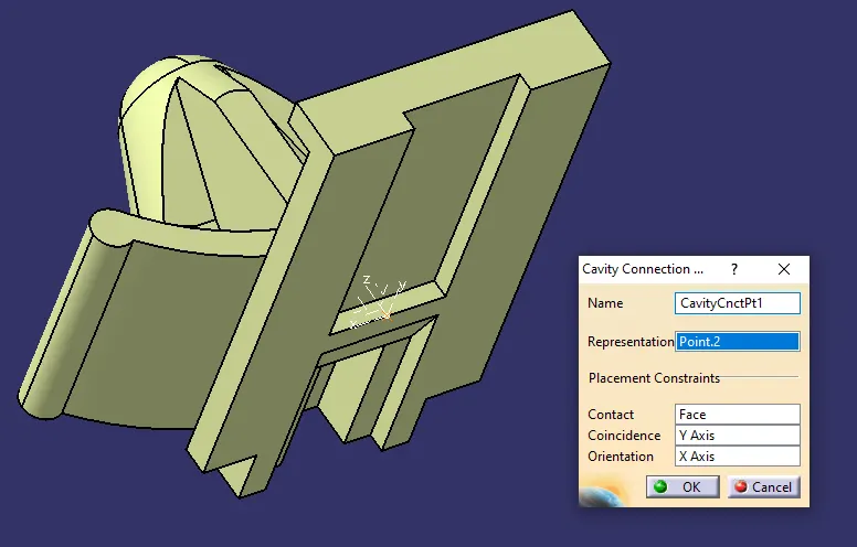
Defining Cavity Connection Point
ASSEMBLING IN ELECTRICAL ASSEMBLY DESIGN
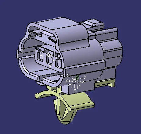
This Assembly product file gets snapped on the L clip using the tools available in Assembly workbench as shown below. Snapping of L clip in appropriate position as shown below.
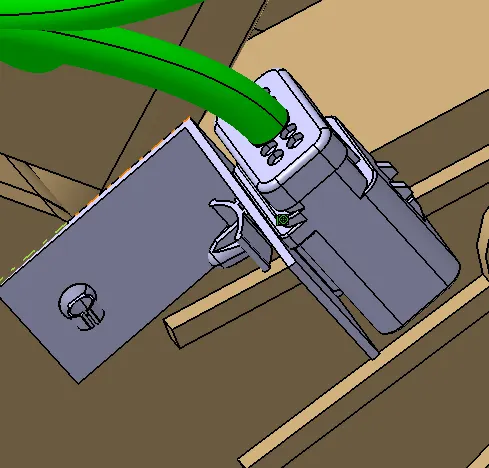
Guiding Channel definition as shown below
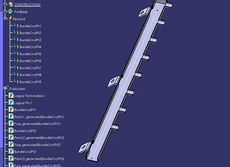
Placement of Guiding Channel in appropriate position using snap option available in Assembly Workbench
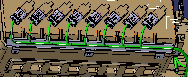
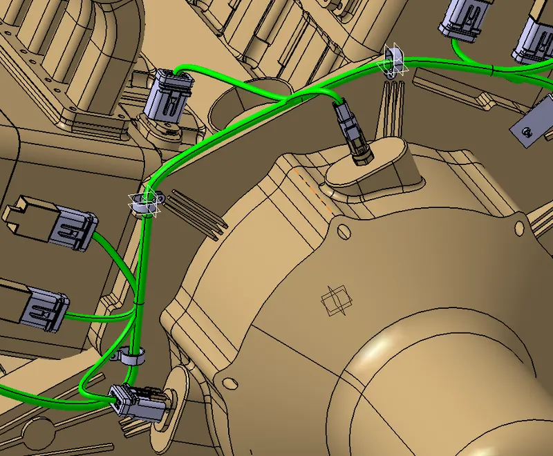
P clamp is defined as a support part and placed in such a manner according to the wiring harness direction like Entry point towards the wiring entry direction and exit on the other side.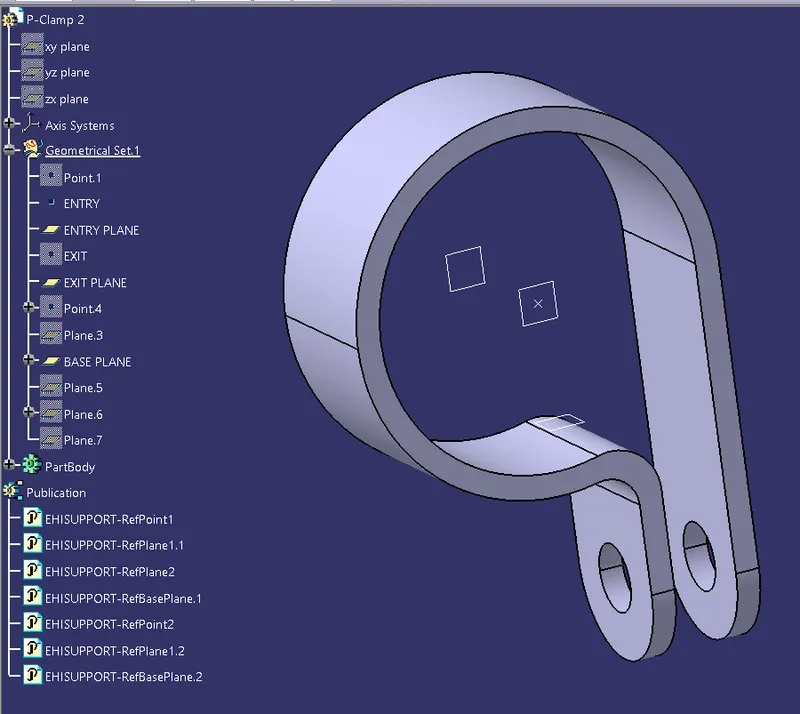 The placement of P clamp in appropriate position on the V-8 Engine as shown below.
G
Electrically component is defined in Electrical Part Workbench [EPW] and harness is generated using Electrical Harness Assembly and Electrical Harness Installation Workbenches and final component is shown below with its tree structure.
//The connecters are snapped to the Engine using snap option available in Assembly Workbench//
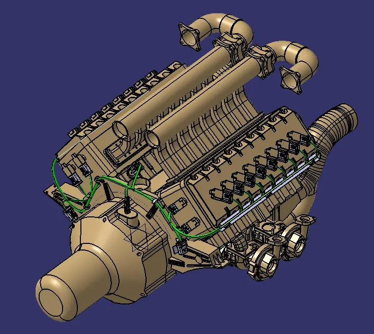
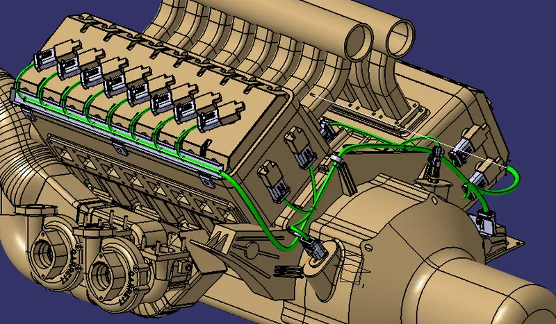
Harness Assembly was flattened using Electrical Harness Flattening [EHF] Workbench.
Harness parameters are set before proceeding to the EHF Workbench.
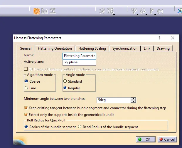
The Assembly Harness is extracted in the Flattening workbench using Extract option and flattened using Flatten tool as shown below. The file is saved with extension .ehf file
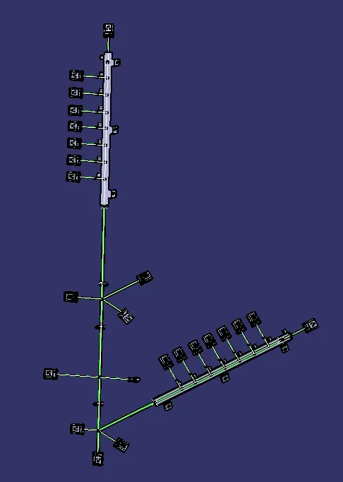
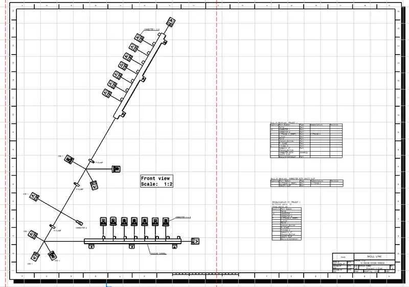
Drawing Workbench is used to generate 2D drawings and it is opened using Files option available in main toolbar. The 2D drawing is generated using front view option and annotated is added using Text Tool with Title and Frame box and Bill of Materials [BOM] as shown below.