Project 1
Question:
Simulate the starting behaviour of a 5 horsepower(3.75kW), 3-phase 3-wire, 230V, 60Hz, 4-pole squirrel cage induction machine with parameters:
rs=0.531Ω,">rs=0.531Ω,rs=0.531Ω, Lls=Llr=2.52mH">Lls=Llr=2.52mHLls=Llr=2.52mH
rf=0.408Ω">rf=0.408Ωrf=0.408Ω, Lm=84.7mH">Lm=84.7mHLm=84.7mH
J=0.1kgm2">J=0.1kgm2J=0.1kgm2
The machine is suddenly connected to a balanced three-phase 230V rms sinusoidal supply voltage at frequency 60Hz. After reaching rated speed the motor is loaded to 0.83 times rated torque at 0.7secs. The load is removed after 0.1sec.
a) Simulate the start-up behaviour of the induction motor represented in the stationary d-q reference frame. Provide simulation plots of vqs(t),iqs(t),ids(t),iqr(t),idr(t),Te(t),Tl(t)andωr(t).
b) Simulate the start-up behaviour of the induction motor represented in the synchronous reference frame. Provide simulation plots of vqse(t),iqse(t),iqre(t),Te(t),Tl(t)andωr(t).
c) Simulate the start-up behaviour of the induction motor represented in the rotor reference frame. Provide simulation plots of vqsr(t),iqsr(t),iqrr(t),Te(t),Tl(t)andωr(t).
d) Simulate the start-up behaviour of the induction motor represented in the rotor flux reference frame. Provide simulation plots of vqsrf(t),iqsrf(t),iqrrf(t),Te(t),Tl(t)andωr(t).The simulations must show both the free acceleration period and the transient load peroid.
Aime:
The aim for this project is to simualte an nduction motor with above leasted parameters then us the motor model to observe the above listed test cases and evaluate the outcome or the result of this simualtion.
Block Diagram:
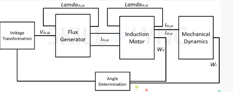
As shown above, i will be simulating an induction motor as above where first we will be having a voltage transformation block with 3-Phase voltage which will be converted to ( dq ) volatge supply. This dq voltage will be used to generate flux in the next block. the flux is going to be having Lamdads and Lamdaqs as stator complements. The current produced from the flux generator will then flow through the motor rotor and then flux will be generated in the motors rotor (Lamdadr and Lamdaqr). All these will the power the dynamics to produce torgue and speed. This then gives us a close loop control of the induction motor since from rotor rotation speed and torgue is obtained, angle of rotation in calculted from rated speed and reference speed and given to the volatge supply (Rotor angle determines the voltage transformation).
Simulation:
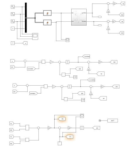
The model is as show above. first we have the voltage transformation and flux generation part.
Voltage Transformation for flux generation:
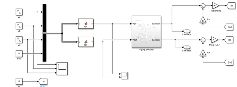
The 3 phase voltage input is given by the three sine waves with the angle thete. Using a buscreator it then given to function block which then transform the three phase votage to dq voltage using the following formulars.
(2/3)*(u(1)*cos(u(4))+u(2)*cos(u(4)-(2*pi/3))+u(3)*cos(u(4)+(2*pi/3)))
(2/3)*(u(1)*sin(u(4))+u(2)*sin(u(4)-(2*pi/3))+u(3)*sin(u(4)+(2*pi/3)))
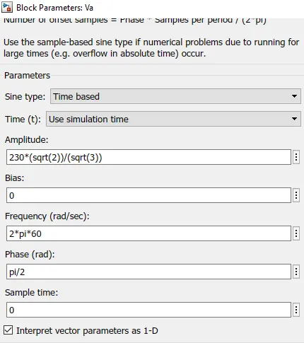
The input voltages are given as below
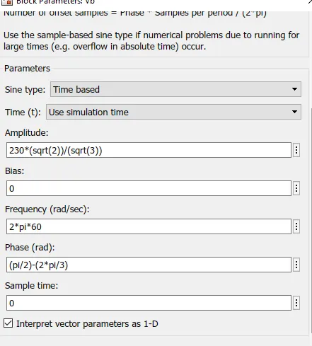
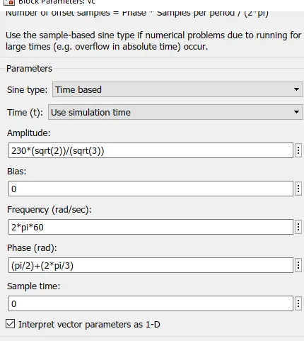
The output of the flux generator subsystem block is Lamdaqs and Lamdads. After subtracting the self magnetizing inductance and rotor current (which are juslt the losses on copper coil). we will have the q axsis and d axsis current respectively.
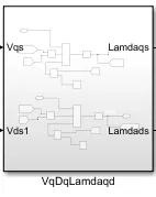
In the flux generation block system, Lamdaqs and Lamdads is calculated as such.
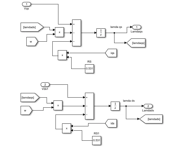
In this block was simply happens is flux is calculated in reference to rotor speed. we have dq voltage suply as input, to generate flux. rotor speed w is multiplyed by previous flux value and subtracted from incoming dq suply. The voltage loss which is simply stator curren multilyed by stator resistance is also subtracted. then intergrated to give the new motor flux.
So its a loop system were the flux, speed and current calculated will be given back for the next calculation.
Induction Motor:
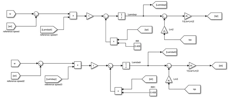
The next part is the induction motor part. The speed is been compared to reference speed and then multiplyed to the rotor flux lincage. Rotor resistance is multilyed by the rotor current to calculate rotor loss by subtraction.
Mechanical Dynamics:
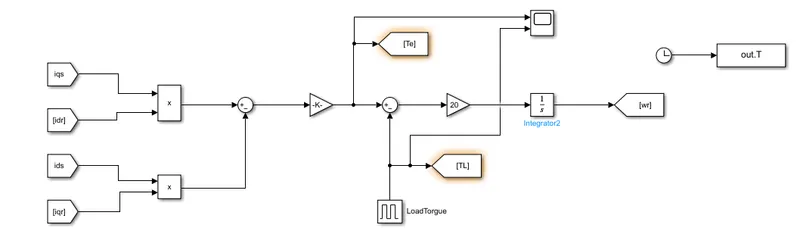
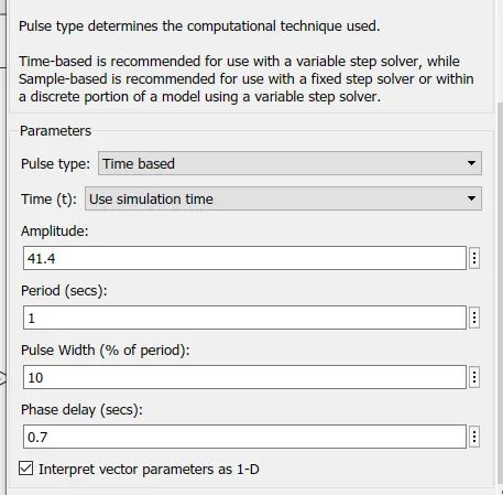
Here stator and rotor current are given as input, then subtracted and multiplyed by torgue constant to get the motor torgue or electromagnectic torgue. The load torgue for this example is given by a pulse generator. This means we will be aplying load to the motor just at some particular time intervals to see how it affects the motor torgue. This is then multiplyed and intergrated to get the actual rotor speed. which is later compared and given to the induction motor.
Recomendations:
For this simulations we are required to have the motor get the blow parameters.
-Motor power. 5 horsepower(3.75kW),
-3-phase 3-wire,
230V, 60Hz, 4-pole
rs=0.531Ω,">rs=0.531Ω, Lls=Llr=2.52mH">Lls=Llr=2.52mH
rf=0.408Ω">rf=0.408Ω Lm=84.7mH
J=0.1kgm2
-From the above inputvoltage images we could see that the motor is powered by a 230V 3-phase suply with 60Hz and 120° phase difference.
-Sator resistance is set to 0.531ohms
-Rotor resistance is set to 0.0408ohms
-Stator and Rotor inductance is set to 2.52mH
-Moot mutual inductance is also set as 84.7mH
-Moment of inertia is given as 0.1kgm^2 which is 1Nm^2
The motor torgue is 50Nm hence aplying a load torgue of 0.83 times motor torgue makes it 41Nm.
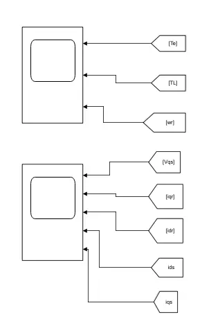
With the help of the scope the required signals to be ploted with be ploted in two separate scpes for more identification of the individual signals.
a) Simulate the start-up behaviour of the induction motor represented in the stationary d-q reference frame. Provide simulation plots of vqs(t),iqs(t),ids(t),iqr(t),idr(t),Te(t),Tl(t)andωr(t).">vqs(t),iqs(t),ids(t),iqr(t),
idr(t),Te(t),Tl(t)andωr(t).
vqs(t),iqs(t),ids(t),iqr(t),idr(t),Te(t),Tl(t)andωr(t).">-For this simulation
theta and Speed (w) are kept 0.
*At stationatry d-q reference theta is 0.
Results:
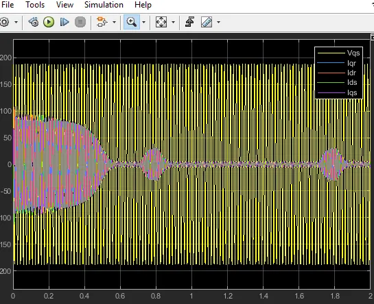
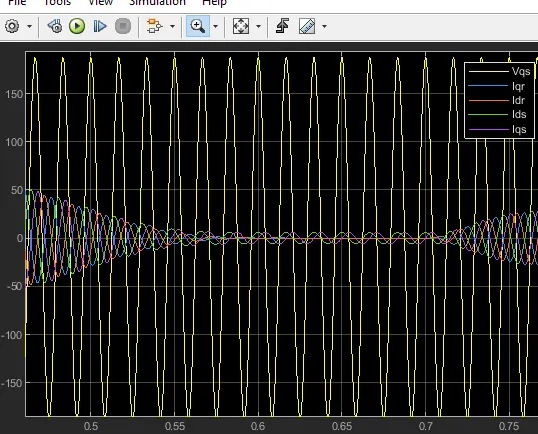
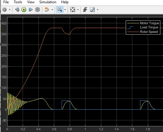
For this simulation we could notice that the rotor runs to almost 380 and
stops when torgue gets to breakdown torgue. the load torgue is aplyed to 83%
of load torgue and rotor speeds slows down while motor torgue trys to catchup
with load torgue. When motor torgue catches load torgue speed stays constant
and only accelerates again when load is taken of the motor. During rhis time
rotor and stator current renduces and lated increases when speed increases.
hence more current is neede by stator and rotor to speed up the rotor.
b) Simulate the start-up behaviour of the induction motor represented in the
synchronous reference frame. Provide simulation plots of veqs(t),ieqs(t),
ieqr(t),Te(t),Tl(t)andωr(t).
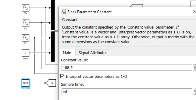
*In the synchronous reference fram the rotor rotates with the speed of the
magnetic field. `Ns = (120F)/(P)`
`Ns = (120*60)/(4)` = 1800 rpm = 188.5rad/s
Resluts:
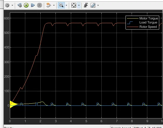
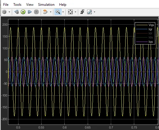
At Synchronous reference the same senarior happens just that the rotor
turns at synchronous speed which is very high since there is very little or no
slipp. For this simulation we could notice that the rotor runs to almost 380 and
stops when torgue gets to breakdown torgue. the load torgue is aplyed to 83%
of load torgue and rotor speeds slows down while motor torgue trys to catchup
with load torgue. When motor torgue catches load torgue speed stays constant
and only accelerates again when load is taken of the motor. During load adding
on the motor very little effect is observed on the current. This is because more
current is need to keep rotor running at higher speeds.
c) Simulate the start-up behaviour of the induction motor represented in the rotor reference frame. Provide simulation plots of vrqs(t),irqs(t),irqr(t),Te(t),Tl(t)andωr(t).
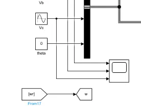
* For this simulation the rotor speed will be given as the starting speed (w)
Results:
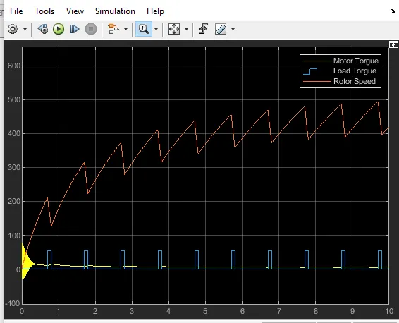
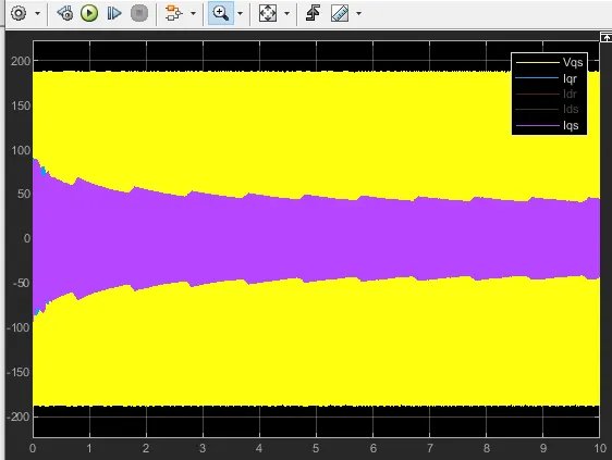
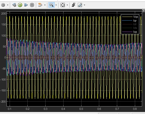
For this simulation we could notice that the rotor runs to almost 380 and
stops when torgue gets to breakdown torgue. the load torgue is aplyed to 83%
of load torgue and rotor speeds slows down while motor torgue trys to catchup
with load torgue. When motor torgue catches load torgue speed stays constant
and only accelerates again when load is taken of the motor. During rhis time
rotor and stator current renduces and lated increases when speed increases.
Hence more current is always needed to speed up the rotor.
d) Simulate the start-up behaviour of the induction motor represented in the
rotor flux reference frame. Provide simulation plots of vrfqs(t),irfqs(t),irfqr(t)
,Te(t),Tl(t)andωr(t).
*for this calcultion the motor flux will b calculated and fed to the reference
speed.
`phi = T/I*K`
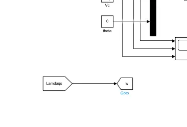
But since we have flux alrady calculated in the flux subsystem. we could use a goto block to give the flux as reference.
Results:
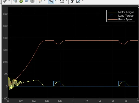
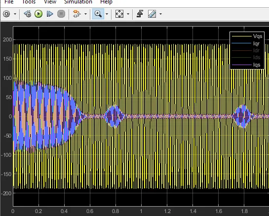
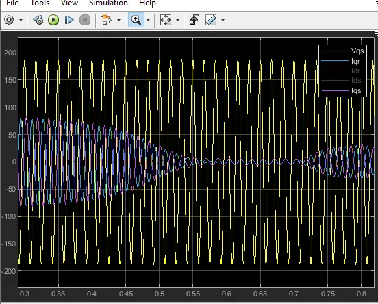
For this simulation we could notice that the rotor runs to almost 380 and
stops when torgue gets to breakdown torgue. the load torgue is aplyed to 83%
of load torgue and rotor speeds slows down while motor torgue trys to catchup
with load torgue. When motor torgue catches load torgue speed stays constant
and only accelerates again when load is taken of the motor. During rhis time
rotor and stator current renduces and lated increases when speed increases.
- Mayur Salunkhevery much helpful to me thank you for your explanation