PROJECT 1 - MESHING IP SUBSTRATE
OBJECTIVE:
To mesh the given CAD model of IP substrate by following the quality criteria given in the data and assigning thickness to it.
Quality criteria:
|
S.No |
Quality Criteria |
Value |
|
1 |
Target/Average length |
4 |
|
2 |
Minimum Length |
2 |
|
3 |
Maximum Length |
6 |
|
4 |
Aspect |
3 |
|
5 |
Warpage |
15 |
|
6 |
Skewness |
45 |
|
7 |
Jacobian |
0.7 |
|
8 |
Minimum Quad Angle |
45 |
|
9 |
Maximum Quad Angle |
135 |
|
10 |
Minimum Tria Angle |
30 |
|
11 |
Maximum Tria Angle |
120 |
|
10 |
Tria Percentage |
15 |
PROCEDURE:
Geometry cleanup and Mid-surface extraction.
- A new .ansa file is opened and the .igs file of the given model is then imported on to the workpage.
- Topology correction is done using Topology module>faces>top. This function automatically creates topological conditions between selected adjacent CONS.
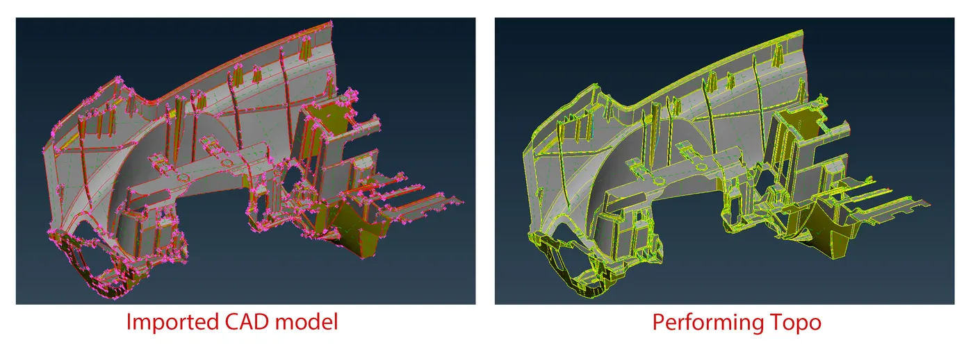
- The model is then viewed in ENT( entity mode) from drawing style to check for any orientiation issues (Top portion should be gray and bottom to be yellow in colour) and if there is any issues its then corrected using Faces>Orient(tool)>visible.
- Turn on the Cross-hatches form Face draw so that surfaces can be selected easily.
- The pixel correction can be done using, Mesh module>Lenght (Perimeter=1, Macro=1). Its can be also done from Topo module using Auxillaries>fine.
- The model is then subjected to geometry check up to find out any missing surfaces, free edges, duplicates etc. Tools tab>Checks>geometry>Execute.
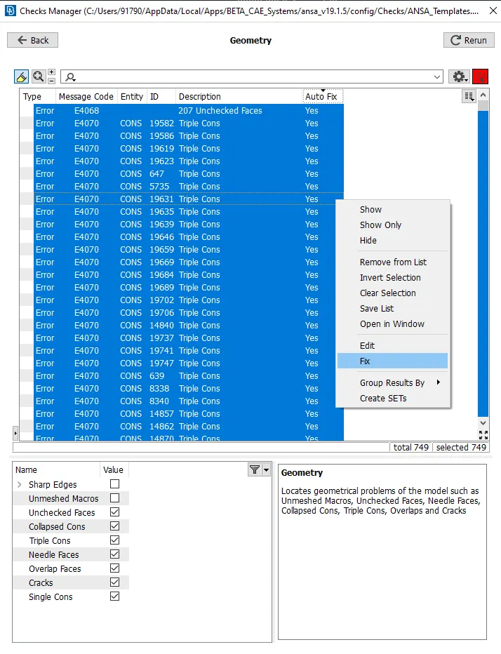
- When check up was carried out, Ansa throwed out error messages, in which some of them can be fixed automatically and others were done manually using other tools.
- After the cleanup the thickness of the model is been measured from different portions.
- Mid-surface of the component is extracted using Faces>Offest or Faces>middle.
- The surfaces can be further modified or created using curves>create, curves>middle, etc. With this mid surface can be captured excately at the middle of the parent gormetry.
- The extracted mid-surface from the part can be seperated out using not, i-not, neighb etc from focus toolbar.
- A new property for extraceted mid-surfaces is then then created using Faces>Set PID>New>P-shell.
- Rename the card and measured thickness is then assigned to it.
- The material is then defined by putting tick mark to the defined box. Other parameters such as youngs modulus, shear modulus, poissons ratio were also enterd, If these values were not entered the software won't consider it as a real object while running simulations.
- Splitting of the surfaces is done accordingly to avoid the failure of elements while meshing and also to get good flow over the mesh.
- These can be done using tools from topology and mesh modules. Join tool from mesh module can be used to toggle off unnecessary single cons.
- If the new surfaces were created using Faces>New>Existing surf, the cons drawn on the surfaces can be removed permanently by using Faces>cut (Right click).
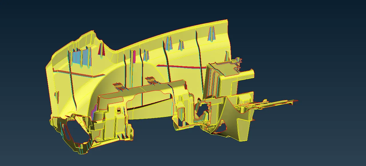
- To check wheather the mid-surface is perfectly captured, The transparency is turned ON for the given model from the property card and then viewing the model in PID (property) mode. Shadow option from drawing mode is also turned on for the better visibility.
Meshing.
- Meshing is done in mesh module and its turned on.

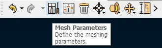
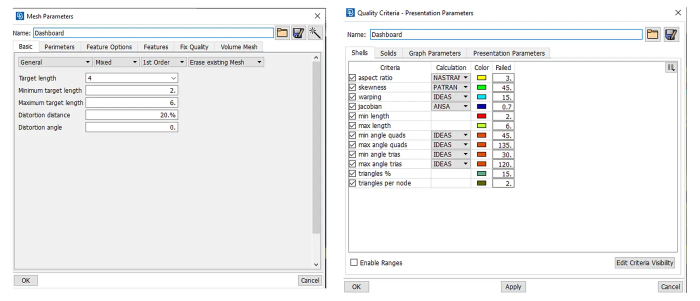
- The mesh parameter from untility is opened to enter the target element size, element type etc.
- Similarly the quality criteria option is also selected from the same toolbar and the values given as per the given data is then entered accordingly. From presentation parameter sub-option, check wheather the percentage element box is ticked also from detailed from demand effect drag the cursor towards all details.
- Along with the given quality criteria, Triangle per node is also turned on. (Two tria elements should not be connected to each other)
- Now each splitted surfaces are meshed seperately using Mesh generation>Batch or Best or spot mesh.
- While meshing its better to capture the surfaces with the given target element size for those in fillet regions it can be meshed with mininum element lenght.
- The surfaces can be again splitted to get good mesh flow using the cut option available in the mesh module and can be toggled after completing the meshing procedure.
- The hole areas can be aligned by controling the positions and number of nodes surrounding it using Mesh module>perimeter>slide or number.
- While meshing it resulted in creation of lots trias and rotational quads which can be again remeshed using Shell mesh> Reconstruct.
- Presence of trias in critical areas such as fillets, cut out regions are not preferable and it can be draged off using split, paste tool,swap etc.
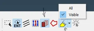
- Swich on the highlight tool to get the visibility while selecting points etc.
- While using split (Mesh module>elements>split), polygonal option from feature selection toolbar can be used to drag off tria to long distance. Show only, highlight option from the same toolbar is further used for the selection as per the need.
- The elements can be arranged uniformly using smooth tool from shell mesh option and while using this tool some of the elements gets displaced from the splitted lines and these can projected on to those line using Grids>origin. Node should lie properly on the surface, no deviation (No kinks).
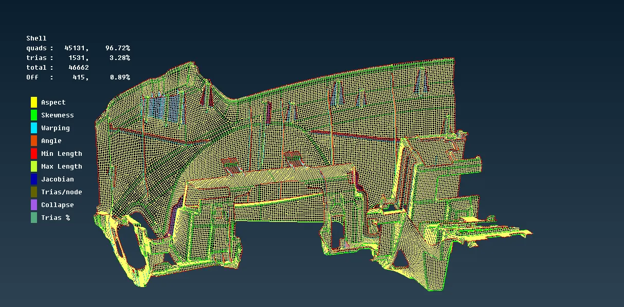
- Quality criteria applied can be viewed using Hidden view> Drawing styles, Where the elements gets highlated in diferent colours indicating the failures to respective criteria and correction has to be made further.
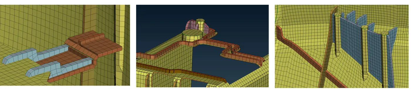
The thickness assigned to the model can be viewed using Utility>Quality criteria>Presentation parameter>Draw shell as solid.
RESULT:
The given CAD model of IP substrate has been mid-surfaced and meshed as per the given element quality criteria and assigned thickness to it.
LEARNING OUTCOMES:
- Geometry clean-up.
- Maunal mid-surfacing using various tools.
- Shell meshing with good mesh flow.
- More knowledge on quality criteria.
- Assigning thickness.
- Time management.
...........................................................................................................................................................................................................................................................................
Files: https://drive.google.com/file/d/1BAT0TD2lToz9KVEioBcRaO-9zxE5oQvI/view?usp=sharing