Project 1
Aim:
To model a double-acting actuator with Simscape Multibody and Simscape. Simscape Multibody is used to model the mechanical system of the cylinder, and Simscape is used to model the hydraulic system. A Translational Multibody Interface block is used to connect the two systems.
Cylinder Model:
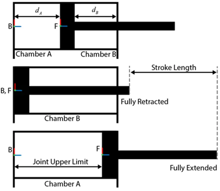
The schematics show the cylinder in three configurations: half-retracted, fully retracted, and fully extended.
The mechanical system of the cylinder is built using Simscape Multibody library components / blocks.
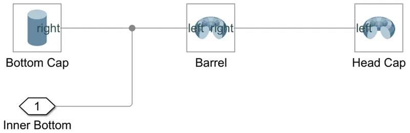
- To model the cylinder and piston, we use the Revolved Solid (Simscape Multibody) and Cylindrical Solid (Simscape Multibody) blocks.
- To provide the translational degree of freedom for the piston, use a Prismatic Joint (Simscape Multibody) block.
- To easily calculate the lengths of the chambers A and B, we can attach the base frame (B) and follower frame (F) of the joint to the centers of the left inner surface of the chamber A and the left surface of the piston, respectively. We need to make sure that the Z-axes of the B and F frames are aligned and both point toward chamber B.
- Using this convention, the length of the chamber A, dA, is the position output of the joint block, and the length of the chamber B, dB, equals the difference of the stroke length and dA. To ensure that the piston does not travel beyond the ends of the cylinder, we can specify the upper and lower position limits of the Prismatic Joint block.
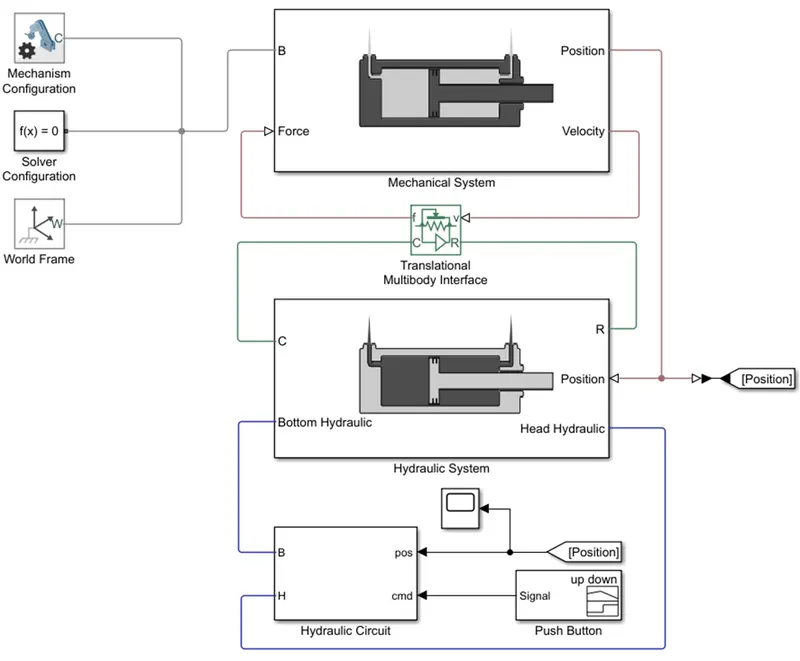
The figure given below shows the block diagram of the double-acting cylinder model which is described above. The model uses two Translational Mechanical Converter (IL) blocks to model the chambers A and B of the cylinder in the Hydraulic System.
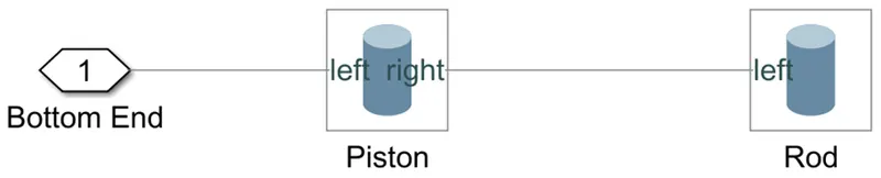
A Translational Multibody Interface block connects the Translational Mechanical Converter (IL) blocks to the Prismatic Joint block.
Mechanical System:

Cylinder assembly:
Piston Assembly:
Hydraulic System:
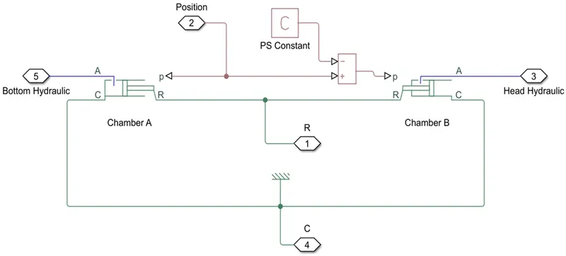
The Prismatic Joint block in the mechanical subsystem provides the position information to the two actuators in the hydraulic subsystem, Chamber B and Bottom Chamber, that have the opposite settings of the Mechanical orientation parameter. The Constant block C provides a position signal offset to the Head Chamber actuator, because when the Bottom Chamber is at dead volume (where position p = 0), the Head Chamber is at maximum stroke.
In chamber A, the pressure at port A moves the piston from 0 to stroke length. The displacement of the piston equals to the position output of the Prismatic Joint block. To model chamber A:
- Connect the ports C and R of the Translational Multibody Interface block to the ports C and R of the upper Translational Mechanical Converter (IL) block, respectively.
- In the Translational Mechanical Converter (IL) block, set Interface displacement to Provide input signal from Multibody joint to enable port p.
- Connect ports p of the Prismatic Joint block and Translational Mechanical Converter (IL) block.
In chamber B, the pressure at port A moves the piston from 0 to negative stroke length. Therefore, we need to change the default orientation and add an offset to the input position signal of the lower Translational Mechanical Converter (IL) block. The offset equals -dB.
- In the lower Translational Mechanical Converter (IL) block, set Mechanical orientationto Pressure at A causes negative displacement of R relative to C.
- Set Interface displacementto Provide input signal from Multibody joint to enable the port p.
- Add a PS Constantblock and specify the constant as the stroke length of the cylinder.
- Add a PS Subtractblock, then connect it to the PS Constant and Prismatic Joint blocks as shown in the diagram. The output of the PS Subtract block equals -dB.
To limit the travel of the piston:
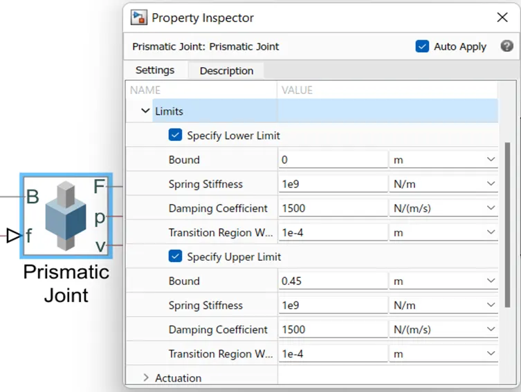
- In the Prismatic Joint block, under the Limitssection, select the Specify Lower Limit and Specify Upper Limit
- Under the Specify Lower Limitsection, the Bound parameter indicates the minimum distance between the frames B and F of the joint block. In this model, we specify the Bound parameter as 0 m.
- Under Specify Upper Limit, the Boundparameter indicates the maximum distance between frames B and F of the Prismatic Joint block. In this model, we specify the Bound parameter as the stroke length of the cylinder.
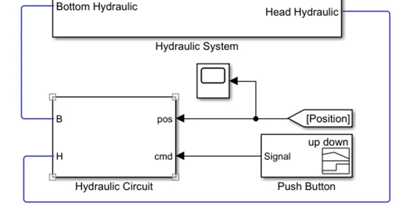
The input command to the hydraulic system is given through a signal builder block and hydraulic circuit.
The hydraulic circuit consists of valve control subsystem and valve subsystem.
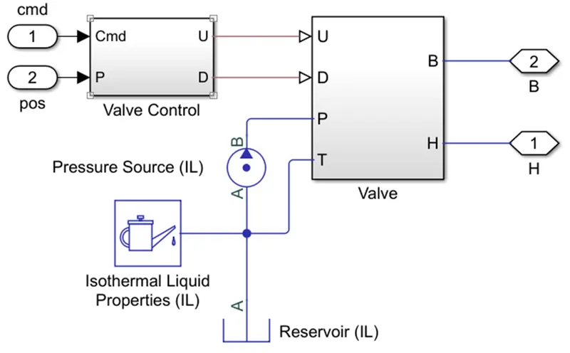
Valve Control Subsystem:
The valve control subsystem has two input signals: command signal specified through a signal builder, and position signal obtained from the prismatic joint in the mechanical system.
The outputs obtained from the valve control subsystem are the restriction areas ‘U’ and ‘D’ for the local restriction (Orifice) in the valve subsystem.
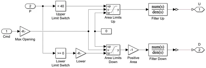
Valve Subsystem:
The valve subsystem contains orifices (Local restriction (IL) block) which models the pressure loss due to a flow area restriction in an isothermal liquid network.
The inputs to the valve subsystem are ‘U’ and ‘D’ which represent the upper and lower restriction areas respectively for the orifice, ‘P’ which represents the input pressure source and ‘T’ which is connected to the Isothermal Liquid properties (IL) and reservoir blocks.
The outputs obtained from the valve subsystem block are ‘B’ and ‘H’ which drives the isothermal liquid conserving port ‘A’ of the bottom (Chamber A) and head (Chamber B) hydraulic chambers respectively in the hydraulic system.
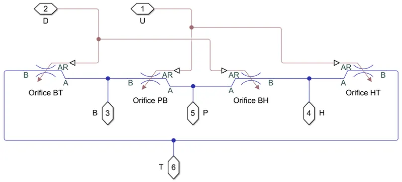
Simulation Results:
The input command defined in the signal builder is as follows:
- 0 from 0 to 1 seconds
- 1 from 1 to 4 seconds
- 0 from 4 to 6 seconds
- -1 from 6 to 9 seconds
- 0 from 9 to 10 seconds
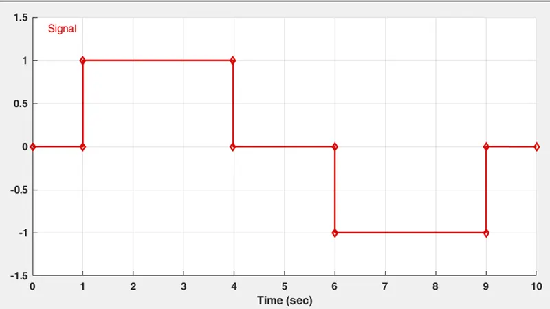
The input command signal is given through the signal builder block to the hydraulic circuit system.
The scope result for position of the piston from the prismatic joint block in the mechanical system is shown below :
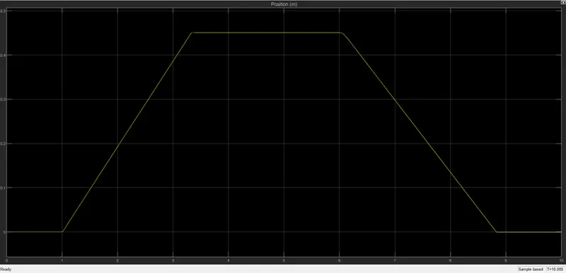
As seen in the results, the piston position:
- Remains at 0 between 0 to 1 seconds.
- Extends from 1 second and reaches the maximum stroke length (0.45m) at 3.3 seconds.
- Remains at maximum stroke length position (0.45m) between 3.3 and 6 seconds.
- Retracts from 6 seconds and falls to fully retracted position (0m) at 8.8 seconds.
- Remains at fully retracted position (0m) between 8.8 to 10 seconds.
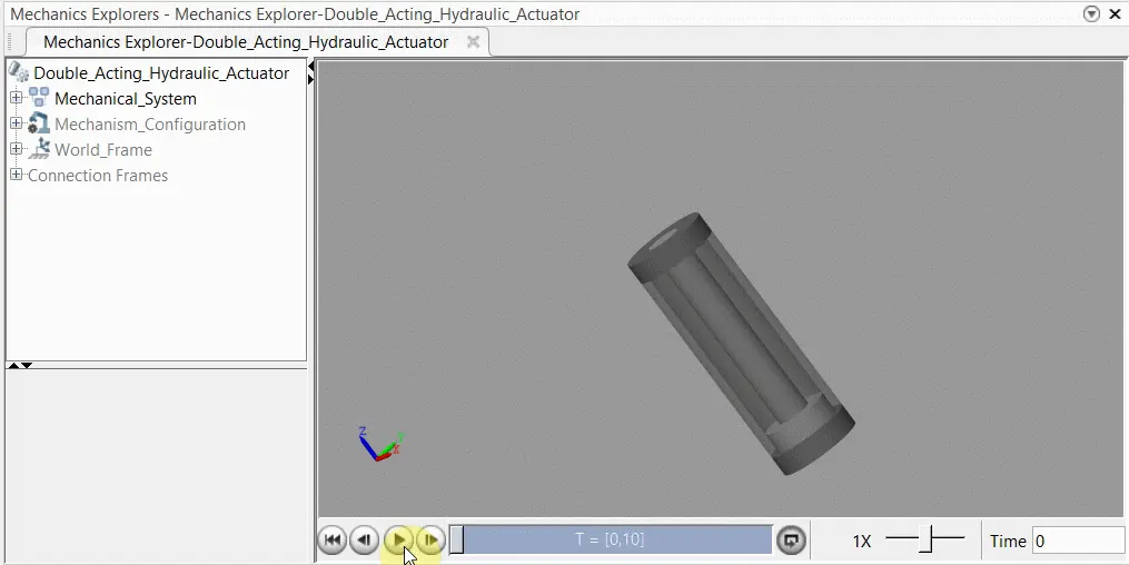
The movement of the piston in the double-acting hydraulic cylinder as seen in the mechanics explorer window is shown below: