Project 1 (Mini Project on Vehicle Direction Detection
MINI PROJECT ON VEHICLE DIRECTION DETECTION
OBJECTIVE:
- The objective of this project is to create a MBD compliant MATLAB Simulink model for vehicle direction detection as per the requirement specified.
- Tag the requirements to the Simulink model, Requirement 1 & Requirement 2 are tagged to their corresponding subsystems.
- Creation of Data Dictionary for the Simulink model, Perform Model In Loop (MIL) test and Software In Loop (SIL) test.
TASK:
- The inputs to the system are the Steering wheel angular input given as yaw rate (Signal name: SteeringWheel_YawDegreeInput) and a input signal from camera (Signal Name: CameraInput_RoadSign), which confirms the occurrence of a road sign.
- A camera reads the road signs & stores into its memory unique values for left turn, right turn & straight drive. Depending on the direction the vehicle takes, a final indication is given to the driver – if he is driving in the recommended direction or not.
- The output of the sytem is a boolean value (Signal Name: Vehicle_Direction_Indicator) which specifies whether the vehicle is turning right, left or going straight.
DEVELOPMENT OF THE SIMULINK MODEL:
The main subsystem 'Vehicle_Direction' along with inputs 'SteeringWheel_YawDegreeInput' , 'CameraInput_RoadSign' and output signal ' Vehicle_Direction_Indicator' is shown below:

Fig 1: 'Vehicle_Direction' subsystem
The main subsystem 'Vehicle_Direction' is further divided into two more subsytems which are 'Requirement1' and 'Requirement2' as shown below:
 Figure 2: 'Requirement1' and 'Requirement2' subsystems
Requirement-1:
- In the 'Requirement1' subsystem, the steering wheel yaw degree (Signal name: SteeringWheel_YawDegreeInput) is fed as input to the subsystem and this value is compared against 3 angular values, one each for left turn, right turn & straight drive (Calibration Values: Right_Turn_AngularLimit, Left_Turn_AngularLimit, Straight_Drive_Steering_Angle) to say which specific direction the steering wheel is turning towards.
- The input signal 'SteeringWheel_YawDegreeInput' is compared against three angular values using the relational operator '==', one each for left turn, right turn & straight drive (Calibration Values: Right_Turn_AngularLimit, Left_Turn_AngularLimit, Straight_Drive_Steering_Angle) to say which specific direction the steering wheel is turning towards. In this case, the output of the relational operator '==' is equal to 1 only when the 'SteeringWheel_YawDegreeInput' matches the calibraton value angular limit specified in Right_Turn_AngularLimit, Left_Turn_AngularLimit, or Straight_Drive_Steering_Angle.
- Three switch blocks are used to implement an if-else logic. The output from each relational operator is given as a condition input (input2) to each switch block. The switch will pass input1 (calibration value) when the condition (input2~=0) condition is satisfied, else input3 (output from the next switch block) is passed as output.
- The signal 'Vehicle_Turn_Status' obtained at the output of the first switch will be a calibration angular value (Right_Turn_AngularLimit OR Left_Turn_AngularLimit, OR Straight_Drive_Steering_Angle). If none of the conditions get satisfied, zero is passed as the output from the last switch. The signal 'Vehicle_Turn_Status' is fed to the outport of subsystem 'Requirement1'.
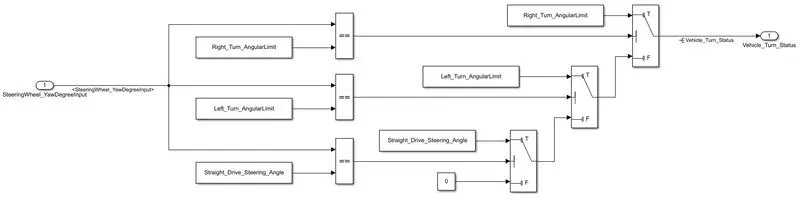 Figure 3: 'Requirement-1' subsystem
Requirement-2:
- In 'Requirement2' subsystem, the local signal 'Vehicle_Turn_Status' fed from 'Requirement1' subsystem is taken as input and is compared against calibration values (RightTurn_RoadSign, LeftTurn_RoadSign, Straight_RoadSign) using the relational operator '=='.
- The boolean value obatined at the output of the realtional operator is compared against a boolean input signal from camera (Signal Name: CameraInput_RoadSign), which confirms the occurrence of a road sign using 'AND' operotor.
- The boolean output signal obtained from each of the three 'AND' blocks are fed to the outport 'Vehicle_Direction_Indicator' to indicate the vehicle direction. The output 'Vehicle_Direction_Indicator' will be a three dimension signal having three boolean elements, with the first element to indicate 'Right Turn', second element to indicate 'Left Turn' and third element to indicate 'Straight Drive'.
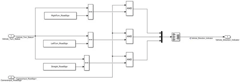 Figure 4: 'Requirement2' subsystem
Requirement Tagging of Simulink Model:
The requirements ‘Requirement-1’ and ‘Requirement-2’ as provided in the Requirements Word document are tagged to their corresponding subsystem in the Simulink Model.
The steps involved in tagging a requirement in the Simulink model is to first highlight the requirement statement in the Word document, then right click on the subsystem in the model that has to be tagged, then select ‘Requirements’ and then ‘Link to Selection in Word’.
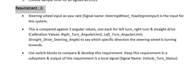
Figure 5: Highlighting the requirement to be tagged in requirement Word document.
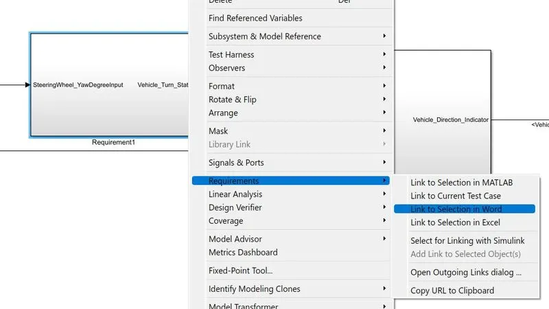
Figure 6: Tagging ‘Requirement1’ subsystem to its requirement in Word document
Creation of Simulink Data Dictionary file (SLDD):
A Simulink Data Dictionary (SLDD) file is created that contains input, output signals and calibration parameters used in the model. SLDD file is created by clicking on Modeling, then ‘Model Properties’, then ‘External Data’ and specifying a file name for the Data Dictionary.
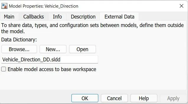
Figure 7: Simulink Data Dictionary Dialog Box
Signals & calibration data list defined in SLDD:
|
Signal / Calibration Name |
Signal Type |
Data Type |
Dimension |
Min |
Max |
Initial Value |
Units |
|
SteeringWheel_YawDegreeInput |
Input |
Int16 |
1 |
-180 |
180 |
- |
Deg |
|
CameraInput_RoadSign |
Input |
Boolean |
1 |
0 |
1 |
- |
- |
|
Vehicle_Turn_Status |
Local |
Int16 |
1 |
-180 |
180 |
- |
Deg |
|
Right_Turn_AngularLimit |
Calibration |
Int16 |
[1 1] |
-180 |
180 |
30 |
Deg |
|
Left_Turn_AngularLimit |
Calibration |
Int16 |
[1 1] |
-180 |
180 |
-120 |
Deg |
|
Straight_Drive_Steering_Angle |
Calibration |
Int16 |
[1 1] |
-180 |
180 |
0 |
Deg |
|
RightTurn_RoadSign |
Calibration |
Int16 |
[1 1] |
-180 |
180 |
30 |
|
|
LeftTurn_RoadSign |
Calibration |
Int16 |
[1 1] |
-180 |
180 |
-120 |
|
|
Straight_RoadSign |
Calibration |
Int16 |
[1 1] |
-180 |
180 |
0 |
|
|
Vehicle_Direction_Indicator |
Output |
Boolean |
3 |
0 |
1 |
- |
- |
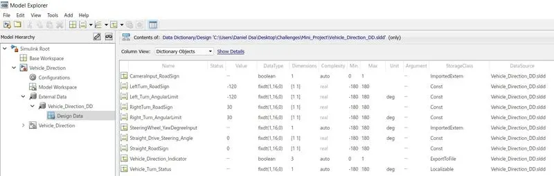
Figure 9: Simulink Data Dictionary Input, Output and Calibration Parameters in Model Explorer
MAAB Guidelines Check in Model Advisor:
A check is performed using ‘Model Advisor’ tool in Simulink to see whether the developed model meets the modeling standards for MAAB.
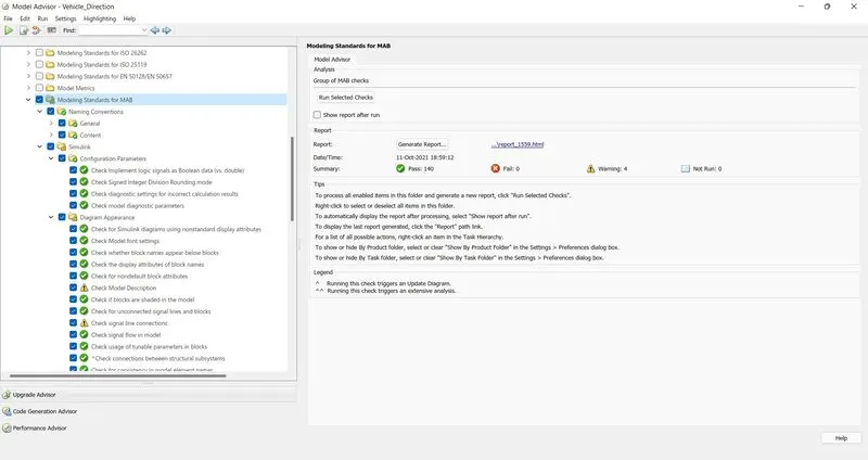
Figure 10: MAAB Guidelines Check in Model Advisor
Creation of Model In Loop Test Harness:
A harness for Model In Loop test is created by right clicking on the main ‘Vehicle_Direction’ subsystem, then selecting ‘Test Harness’ and then ‘Create for Vehicle_Direction’.
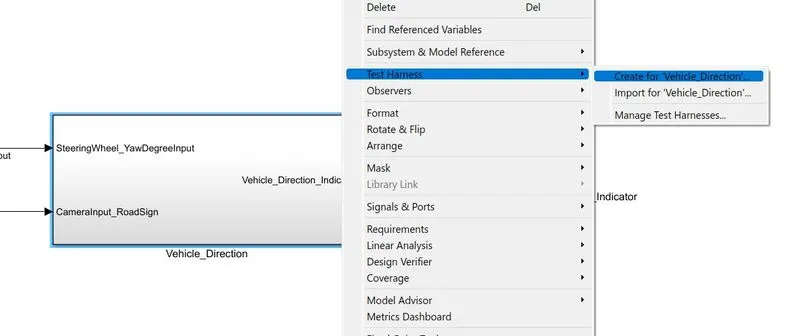
Figure 11: Creation of MIL Test Harness from Main Subsystem ‘Vehicle_Direction’
The input signal of the MIL test harness is a signal builder block and the output signal ‘Vehicle_Direction_Indicator’ is given to a workspace.
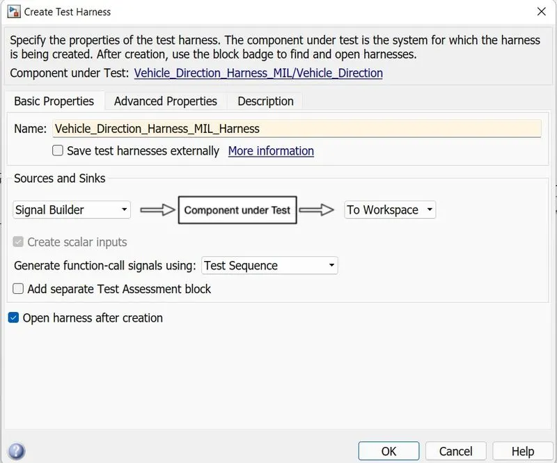
Figure 12: Create Test Harness Dialog Box

Figure 13: Model In Loop Test Harness
The test signals are 'SteeringWheel_YawDegreeInput' and ‘CameraInput_RoadSign’ whose values at different time are specified in an excel sheet and then imported into the signal builder block.
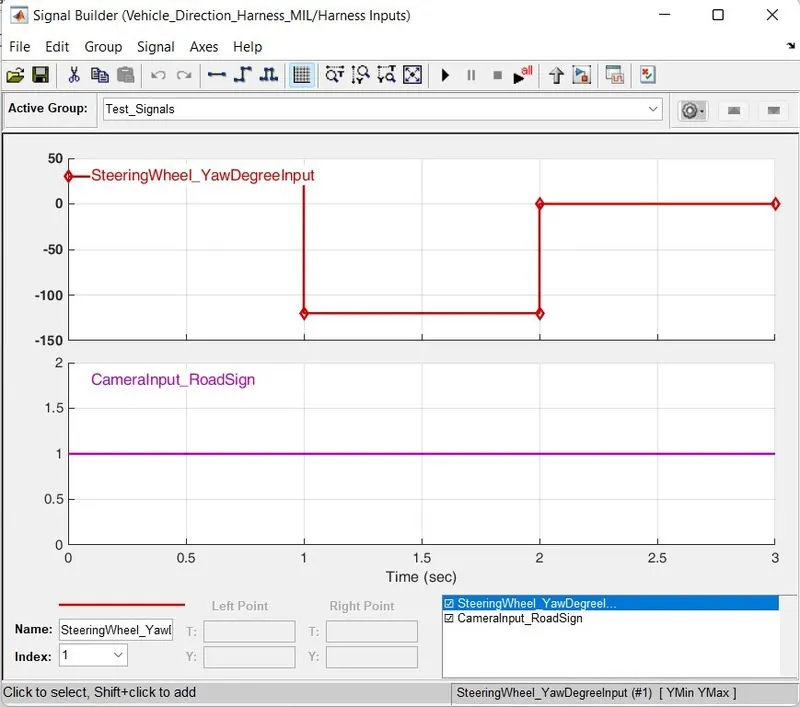
Figure 14: Signal Builder block test signals for 'SteeringWheel_YawDegreeInput' and ‘CameraInput_RoadSign’
Creation of Software In Loop Test Harness:
In order to create a Software In Loop block from the main ‘Vehicle_Direction’ subsystem, the steps followed is to right click on the subsystem, then select C/C++ code, then ‘Generate S-Function’.
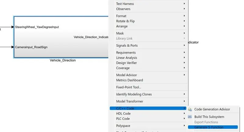
Figure 15: Creation of S-Function block from ‘Vehicle_Direction’ subsystem’
In the ‘Generate S-Function for Subsystem’ dialog box, ‘Create Software-In-the =-Loop (SIL) block’ is checked and build is clicked to create a SIL block for ‘Vehicle_Direction’. The SIL test can be done by replacing the subsystem ‘Vehicle_Direction’ in the MIL test with the SIL block.
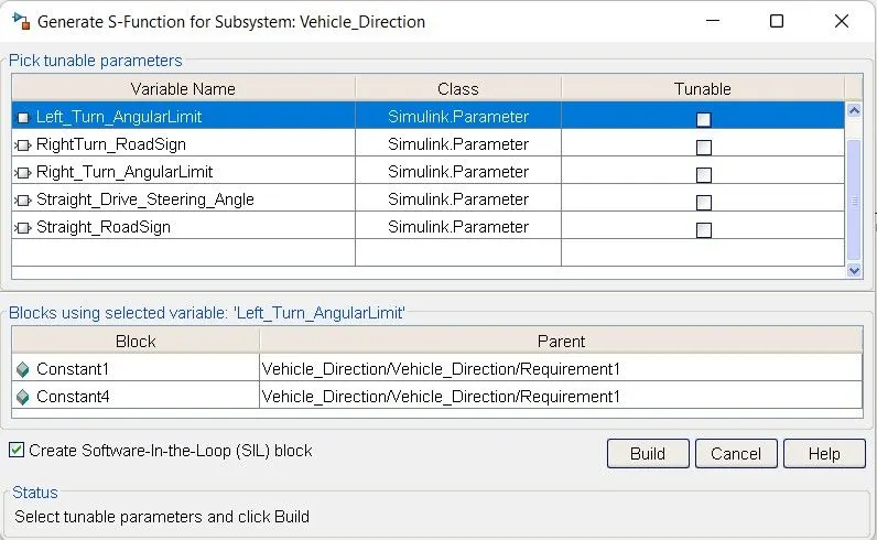
Fig 16: Generate S-Function for Subsystem Dialog Box

Fig 17: SIL test harness for Vehicle_Direction
RESULTS:
Test is performed for the developed model using Model In Loop (MIL) and then Simulation In Loop (SIL) test. The test is carried out for three seconds duration with step time for all signals set as 0.01s.
The input signal ‘CameraInput_RoadSign’ value is set as ‘1’ between 0 and 3 seconds to confirm the occurrence of a road sign.
The input signal ‘SteeringWheel_YawDegreeInput’ is value is set as:
- ‘30’ between 0 to 1 seconds which matches with the value of the calibration parameter ‘Right_Turn_AngularLimit’ in ‘Requirement1’ subsystem and parameter ‘RightTurn_RoadSign’ in ‘Requirement2’ subsystem. The output signal ‘Vehicle_Direction_Indicator’ whose dimension is ‘3’ will have a boolean value [1 0 0] to indicate Right Turn between 0 and 1 second.
- ‘-120’ between 1 to 2 seconds which matches with the value of the calibration parameter ‘Left_Turn_AngularLimit’ in ‘Requirement1’ subsystem and parameter ‘LeftTurn_RoadSign’ in ‘Requirement2’ subsystem. The output signal ‘Vehicle_Direction_Indicator’ whose dimension is ‘3’ will have a boolean value [0 1 0] to indicate Left Turn between 1 and 2 second.
- ‘0’ between 2 to 3 seconds which matches with the value of the calibration parameter ‘Straight_Drive_Steering_Angle’ in ‘Requirement1’ subsystem and parameter ‘Straight_RoadSign’ in ‘Requirement2’ subsystem. The output signal ‘Vehicle_Direction_Indicator’ whose dimension is ‘3’ will have a boolean value [0 0 1] to indicate Straight Drive between 2 and 3 second.
The simulation is run for three seconds first using the MIL test harness and then SIL test harness and the results for output signal ‘Vehicle_Direction_Indicator’ is copied from the workspace into an excel sheet ‘Test_Report_Data’ to check whether the results match the expected output.
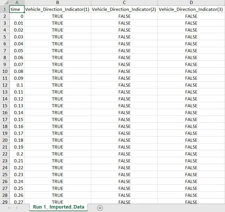
Fig 18: Output signal ‘Vehicle_Direction_Indicator’ values taken from workspace after simulation run.