Rear suspension assembly solid meshing using ANSA
AIM: -
Perform meshing and deploy connection for a suspension system.
OBJECTIVE:
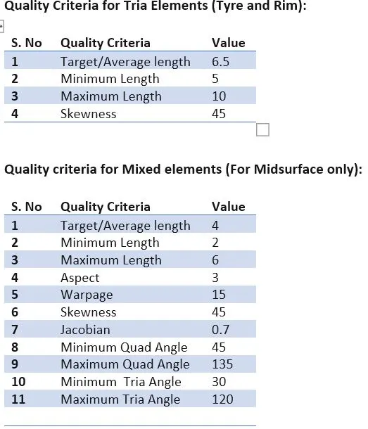
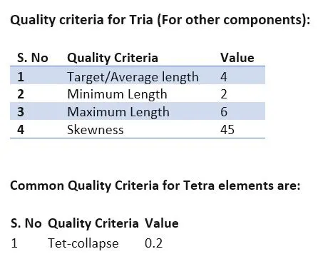
For the given assembly, check for the geometrical errors and mesh with the given element Quality criteria. After meshing the component, the thickness has to be assigned for mid surfaces. Use tetra elements to model non-uniform thickness components. Also, use connections to connect the component.
INTRODUCTION:
What is suspension?
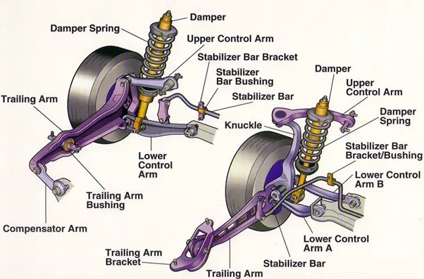
A system of mechanical linkages, springs, dampers that is used to connect the wheels to the chassis is known as a suspension system. It has usually done two works-controlling the vehicle’s handling and braking for safety and keeping the passengers comfortable from bumps, vibrations, etc.
Functions of Suspension System
To prevent the stability of the vehicle in pitching or rolling while in motion.
To safeguard the occupants from road shocks.
A suspension system prevents the road shocks from being transferred to the vehicle frame.
To provide good road holding while driving, cornering, and braking.
To maintain proper steering geometry.
COMPONENTS OF THE SUSPENSION SYSTEM
A suspension system irrespective of its type has some main components in common that are: -
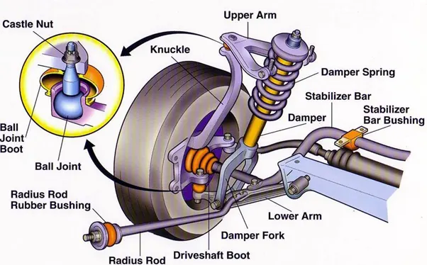
- Knuckle or Upright-
It is the component of the suspension system that is mounted over the wheel’s hub through which the wheels and the suspension of the vehicle connect with each other by the linkages provided.
A knuckle is provided with the king-pin and the caster angles that help the front wheels of the vehicle to steer in a right or left direction which in turn steers the vehicle.
A knuckle provides housing for central bearing over which the wheel’s hub rotates along with the rotation of the wheels.
- Linkages-
linkages are the rigid connections that are used in the suspension system to connect the mainframe of the vehicle with the knuckle of the wheels through mechanical fasteners.
On the basis of the type of suspension used linkages are of 3 types-
- Wishbones or A-arm –
It is the type of mechanical linkage which is in the shape of the alphabet A, the pointy end of the A-arm is fastened to the knuckle and the other 2 ends of the A-arm are fastened to the mainframe of the vehicle.
On the basis of the application of the vehicle, either a single A-arm or double A-arm is used. - Solid axle or live axle-
It is the type of linkage which is used to connect the mainframe of the vehicle with the knuckle on the wheel, this is the solid axle casing that supports the overall weight of the vehicle, this type of linkage can be seen in trucks.
iii. Multiple links-
Instead of using double wishbone or solid axle linkage, various high-end cars are adopting multiple link types of suspension in which multiple solid links are used to connect the mainframe of the vehicle to the knuckle on the wheel.
- Shock absorbers or springs-
They are the flexible mechanical components that are used to absorb shock provided by the road condition and are placed between the linkages (wishbone. Solid axle, multi-links) and the mainframe such that the road shock is minimized before transmitting to the mainframe of a vehicle.
On the basis of the application and type of suspension used shock absorbers are of many types that are-
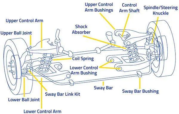
- Spring and damper type shock absorber-
- It is the type of shock absorber in which a pneumatic or hydraulic piston is known as the damper is used that provides damping by absorbing the road shocks.
This damper is surrounded by a compression coil spring which is an elastic mechanical constraint that compresses when force is applied by the bump and recoil back or regains its original shape and size when the force is removed.
It is used to maintain the surface contact of the tires with the road by providing stiffness (resistance to compress), also maintain the damper at its original length after absorbing the shock.
- Leaf spring-
- It is the type of spring in which a number of ductile metal plates called leaf are arranged in a special pattern i.e. one over one in ascending order of their length, leaves of the leaf spring shock absorber are pre-stressed such that when the shock is transferred by the wheels these pre-stressed leaves being ductile tries to regain their original shape i.e. straighten,. Due to which shock is absorbed by the leaves.
This type of shock absorber can be easily seen in trucks on the road in which leaf spring shock absorber is used in between the solid or live axle and the mainframe of the vehicle.
- Air spring-
It is the latest type of shock absorber which can be easily seen in Volvo buses, in air spring shock absorbers the damping of shock is a function of air compression, which means air is used as a shock absorber.
The air needed for different load conditions is controlled and monitored by the Electric control unit of the vehicle.
Struts: -
Another common dampening structure is the strut — basically, a shock absorber mounted inside a coil spring. Struts perform two jobs: They provide a dampening function like shock absorbers, and they provide structural support for the vehicle suspension. That means struts deliver a bit more than shock absorbers, which don't support vehicle weight — they only control the speed at which weight is transferred in a car, not the weight itself.
Because shocks and struts have so much to do with the handling of a car, they can be considered critical safety features. Worn shocks and struts can allow excessive vehicle-weight transfer from side to side and front to back. This reduces the tire's ability to grip the road, as well as handling and braking performance.
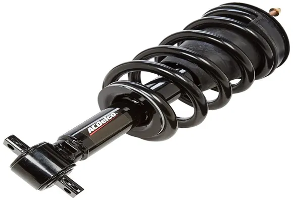
Trailing Control Arm: -
The biggest issue with a solid axle is that there is nothing to stop side to side or forward and backward movement. Leaf springs are used to stop the movements but only the top and bottom ones and it is not good at it either. In comes trailing control arm which can prevent forward motion and side to side motions.
Advantages
- Trailing control arms negate any and all the motion that the solid axle experiences. This includes side to side movement and forward movement by locking down the axle using the control rods.
- Similar to leaf springs trailing control arms are also really strong and durable.
- It can be paired with a Panhard Rod and thus negating one of its disadvantages.
Disadvantages
- It cannot stop lateral movement at all and may cause issues with it. Any vehicle that will go through a more vertical movement cannot use this system.
- Other disadvantages carried over from leaf are a lot of unsprung weight making it unpredictable.
- If a vehicle needs to prevent lateral motion, they employ the use of the next system.
TYPES OF SUSPENSION SYSTEM
1) INDEPENDENT SUSPENSION SYSTEM
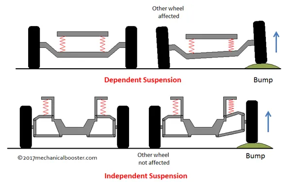
This system means that the suspension is set up in such a way that allows the wheel on the left and right side of the vehicle to move vertically independent up and down while driving on an uneven surface. A force acting on the single wheel does not affect the other as there is no mechanical linkage present between the two hubs of the same vehicle. In most of the vehicles, it is employed in front wheels.
This type of suspension usually offers better ride quality and handling due to less unsprung weight. The main advantage of independent suspension is that they require less space, they provide easier steerability, low weight, etc. Examples of Independent suspension are
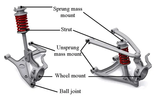
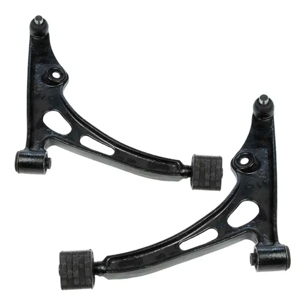
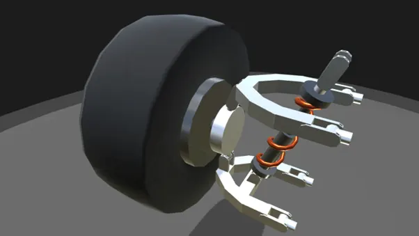
- Double Wishbones:
It is an independent suspension system design using two wishbone-shaped arms (called A-ARM in the USA and WISHBONE in the UNITED KINGDOM) to locate the wheel. Each wishbone or arm has two mounting points to the chassis and one joint at the knuckle. The angle movements of the compressing and rebounding wheels can be managed by using arms of unequal length.
The main advantage of the double-wishbone suspensions is that they allow easy adjustments of camber, toe, and other properties. This type of suspension also provides increasing negative camber gain all the way to full jounce travel. On the other hand, it takes more space and is slightly more complex than the other system like the Macpherson strut. It also offers less design choice.
2.MacPherson Strut:
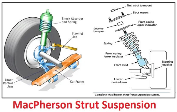
This type of independent suspension got its name from Earle S. McPherson who developed this design. The MacPherson strut is a further development of the double-wishbone suspension. The main advantage of the MacPherson is that all the parts providing the suspension and the wheel control can be combined into one assembly.
It makes it easy to fit in transverse engine. This design is very popular due to its simplicity and low manufacturing cost. The disadvantage is that it is more difficult to insulate against road noise. for this, an upper strut mount is necessary, which should be decoupled as possible. It also requires greater clearance height.
2) DEPENDENT SUSPENSION SYSTEM
IN Dependent Suspension there is a rigid linkage between the two wheels of the same axle. A force acting on one wheel will affect the opposite wheel. For each motion of the wheel caused by road, irregularities affect the coupled wheel as well.
It is mostly employed in heavy vehicles. It can bear shocks with a great capacity than independent suspension. An example of this system is
- Solid Axle.
A solid axle or beam axle is a dependent type of suspension. It is mostly used in rear wheels in which the rear axle is supported and located by two leaf springs. The vertical movement of one wheel influences the other. They are simple and economical to manufacture.
They are so rigid that there is no change in track width, toe-in and camber on a full bump which helps in the low wearing of tires. The main disadvantage is that the mass of the beam is included in the unsprung weight of the vehicle which results in low ride quality. The cornering ability is also poor due to zero camber angle.
3) SEMI-INDEPENDENT SYSTEM
This type of system has both the characteristics of a dependent as well as independent suspension. In semi-independent suspension, the wheel moves relative to one another as in independent suspension but the position of one wheel has some effect on the other wheel. This is done with the help of twisting suspension parts. An example of semi-independent is
- Twist Beam
The twist-beam suspension also known as the torsion-beam axle. These are mostly based on C or H-shaped members. The cross beam of the H-shape holds the two trailing arms together and provides the roll stiffness to the suspension.
It is mostly used in the rear wheel of cars. It is very favorable due to its low cost and it is very durable. It is simple in design and is very light in weight. But on the other side the camber angle is limited and the roll stiffness is also not very easy.
METHODOLOGY: -
- Importing the model into ANSA and checking for geometrical errors
- Dividing the components into small parts and setting different PID
- Giving the quality criteria and mesh parameters
- Performing the Mesh
- Deploying the Connections
- Transforming
PROCEDURE:
Step 1: Importing the model into ANSA and checking for geometrical errors:
First, the CAD-based model of the suspension system is imported into ANSA.
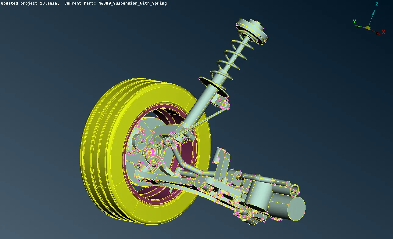
Fig1 – the suspension system mode is imported into ANSA
Checking for geometrical errors: -
It is important to check the model to see if there are no single cons and overlapped surfaces due to triple cons. This is done to avoid any errors in the volumetric mesh as the model has to be closed with no overlapping surfaces
Check Manger > Check >Geometry> Execute
Here the errors we have encountered are
Triple cons
Single cons
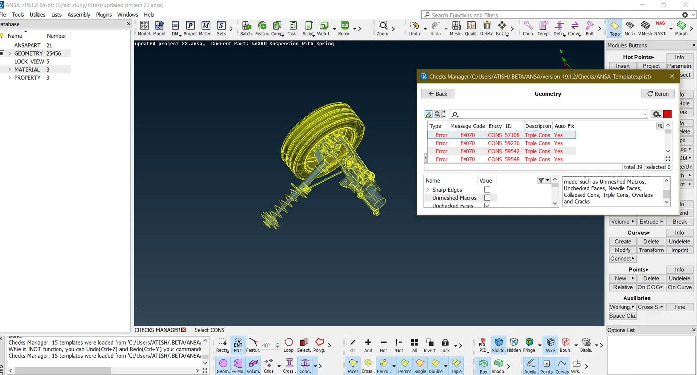
Fig2 – errors encountered in the suspension model
Triple cons can be released to see if there are any additional faces created, then that can be eliminated
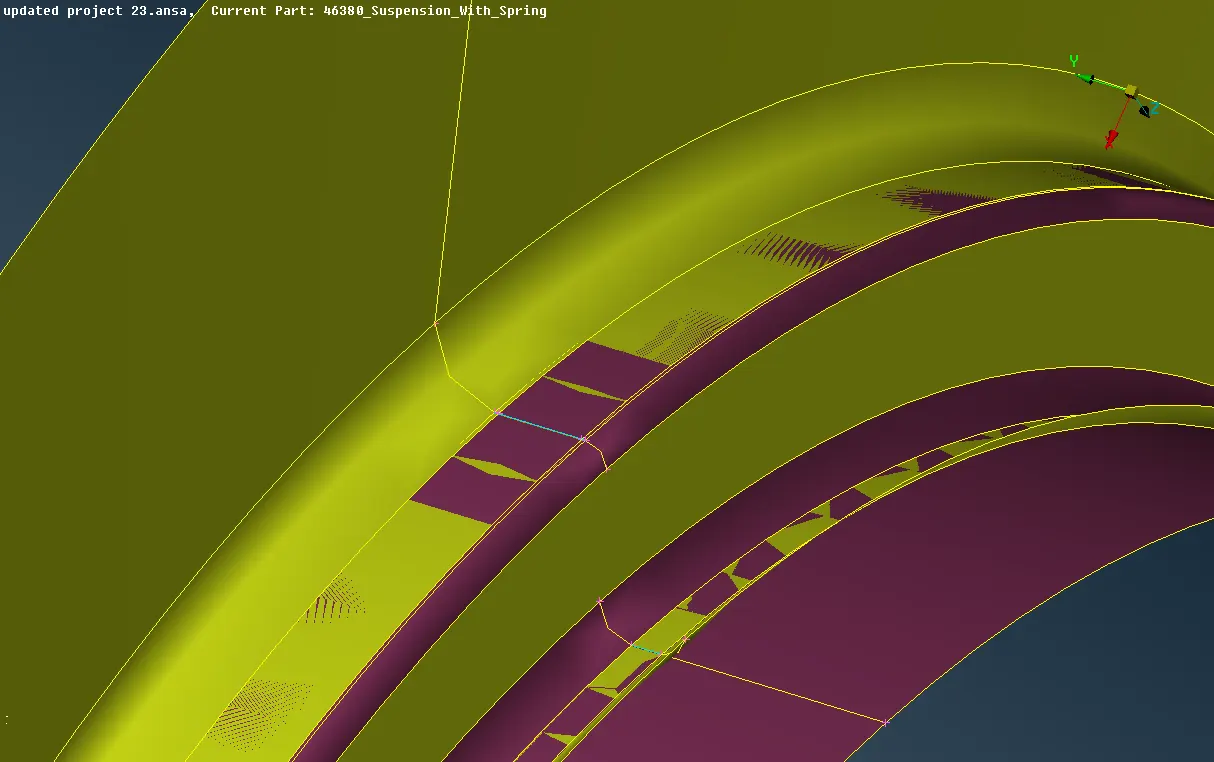
Fig 3- Triple cons due to overlapping of two surfaces
Here the tire and the rim surfaces are overlapping over each other forming triple cons. They can be resolved by simply releasing the joining the cons separately to their specific regions.
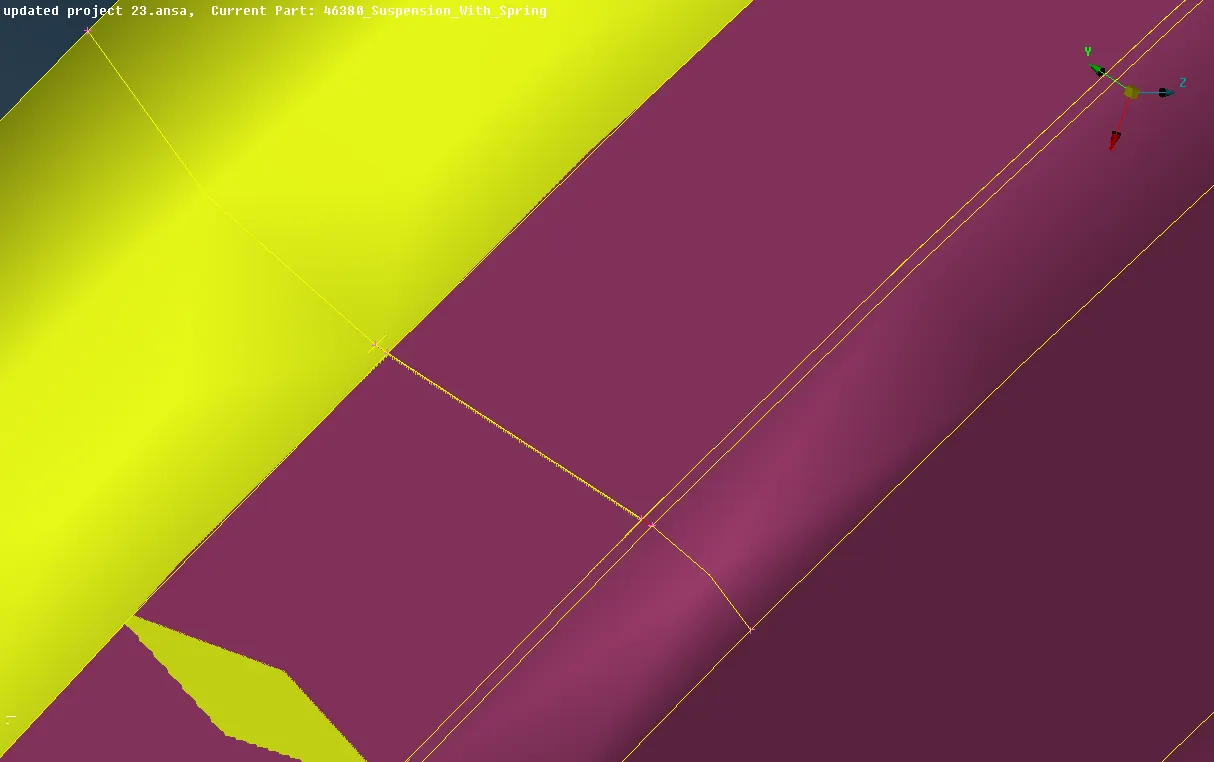
Fig 4- triple cons error is resolved
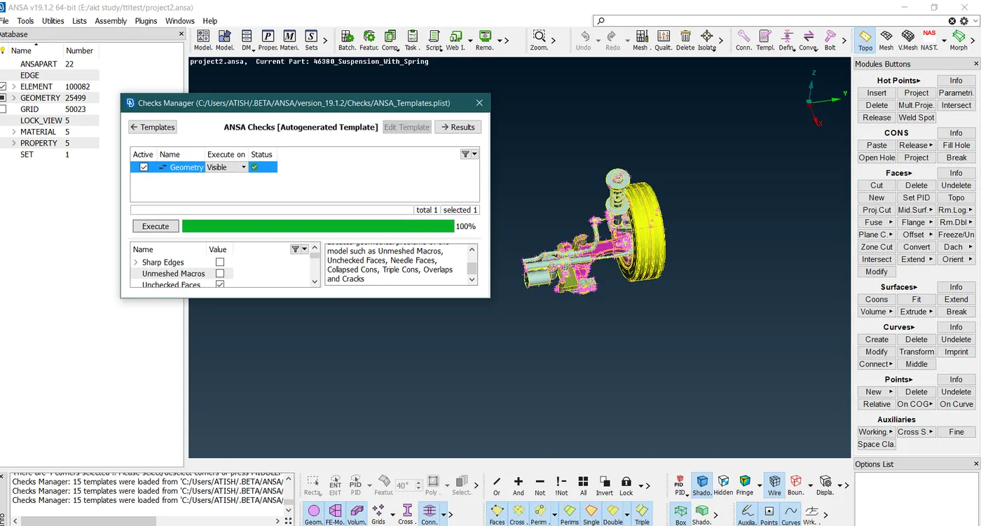
Fig 5- the model is cleaned with no errors
Step 2- Dividing the components into small parts and setting different PID:
The suspension system cannot directly mesh because there are small inside surfaces connected using a joint. So here the whole component is divided into small parts as
- Rim
- Tire
- Brake disc
- Brake kit
- Knuckle
- Sway bar
- Tie rod
- Strut
- Wheel hub
- Trailing rod
- Any many more
Using the!NOT, AND, NOT functions the component is separated. The below picture shows the PID window of the component.
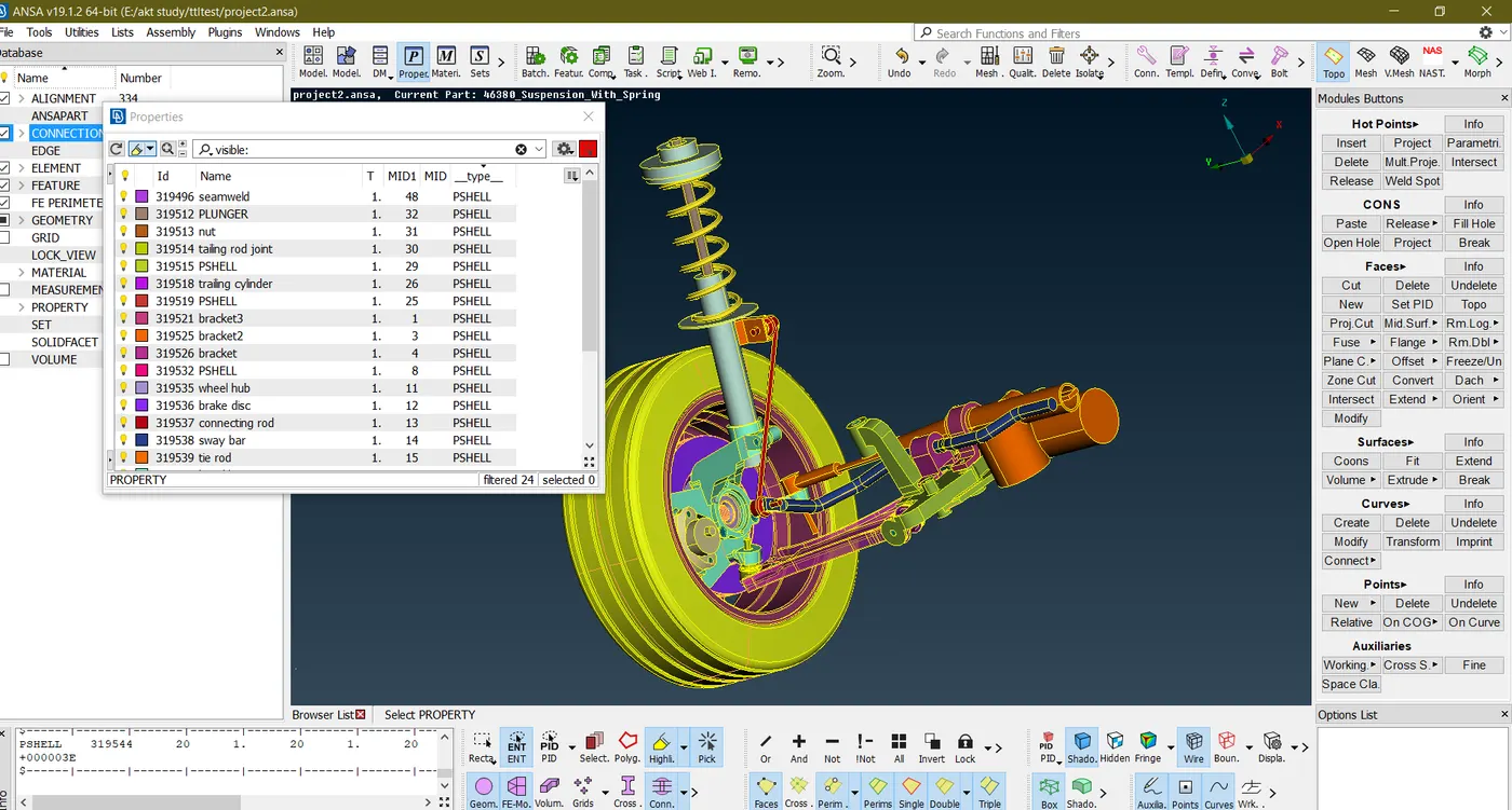
Fig 6- assigning the PID to each component
Step 3 - Giving the quality criteria and mesh parameters: -
Literature on mesh criteria: -
2-D criteria
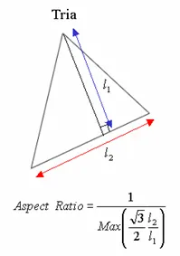
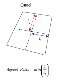
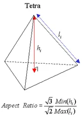
- Aspect Ratio:
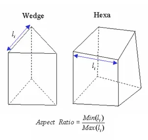
The aspect ratio of 2D element is defined as the ratio of its shortest edge length to its longest edge length. A square has an aspect ratio of 1 since its sides have the same length. As it gets away from the square shape, the aspect ratio becomes smaller than 1.
- Skew Angle
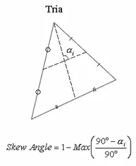
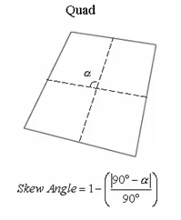
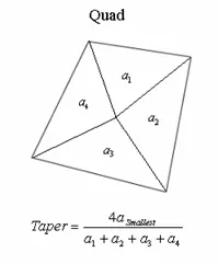
An angle is formed by the two lines which pass through the midpoints of the sides of the quadrilateral. The skew angle represents the absolute value of the difference between the angle and 90 degrees. A rectangle has a skew angle of 0 since the formed angle between lines is 90 degrees. For the triangle and quadrilateral elements, the skew angle is found as shown in the figure. For solid elements (Tetra, Hexa, Wedge), it calculates the skew angle for each element's faces and assigns with the minimum value.
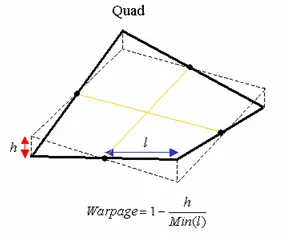
- Warpage
The warpage of the quadrilateral elements is defined as the deviation from a best-fit plane that contains the element. It is not always a case to define a plane with 4 nodes. Therefore, a node of the quadrilateral element may be formed outside of a plane. The warpage is a measurement of how this node has deviated, and as it gets closer to 0, the element becomes more planar. For the quadrilateral elements, the warpage is found as shown in the figure. For solid elements (Hexa, Wedge), it calculates the warpage for each element faces and assigns with the maximum value.
- Jacobian Ratio
The Jacobian calculation is done at the integration points of elements commonly known as Gauss Point. At each integration point, Jacobian Determinant is calculated, and the Jacobian ratio is found by the ratio of the maximum and minimum determinant value. The Jacobian Determinant of 2D elements is calculated after it has been projected onto a plane, and the determinant of 3D elements is found by direct calculation.
If the quadrilateral element is not convex, the negative Jacobian ratio will be obtained, and elements with the negative Jacobian Ratio cannot be solved with the correct result.
3D mesh criteria:
- Tet collapse
Tet collapse is an important criterion that will be dealing with the volumetric mesh also it is only applicable to the tetra elements only. As we know that tetra element is 4 nodded elements having 4 sides and 4 nodes.
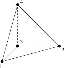
Tet collapse or TET element is the minimum of (h/)÷1.24
Where h is the perpendicular distance from a node to the opposite face of the TET and
A is the area of the opposite face
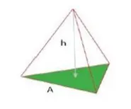
Then if the height of any tetra element falls below the desired height, it will eventually fail for the Tet collapse
There are 2 methods to solve the TET collapse as studied in the article
Article: - skill-lync.freshdesk.com/support/solutions/articles/43000568757-how-to-solve-tet-collapse-in-tetra-unstructured-mesh-
- MV free
- Fix quality
Step 4-Performing the Mesh:
Volume mesh:
The volume mesh is carried out with the meshing of the surface in 2D mode using the tria elements only then they are defined as volume in later stages of the meshing.
Here we are using the SPOT mesh as the algorithm for the spot mesh is quite better than the best and free methods. The quality criteria provided here are different for the whole assembly.
Starting with the tire and rim all the criteria are fitted as they have the same parameters and quality. The average length for the tire and rim is 6.5 that can be set using the LENGTH tool.
LENGTH >PERIMETERS > 6.5
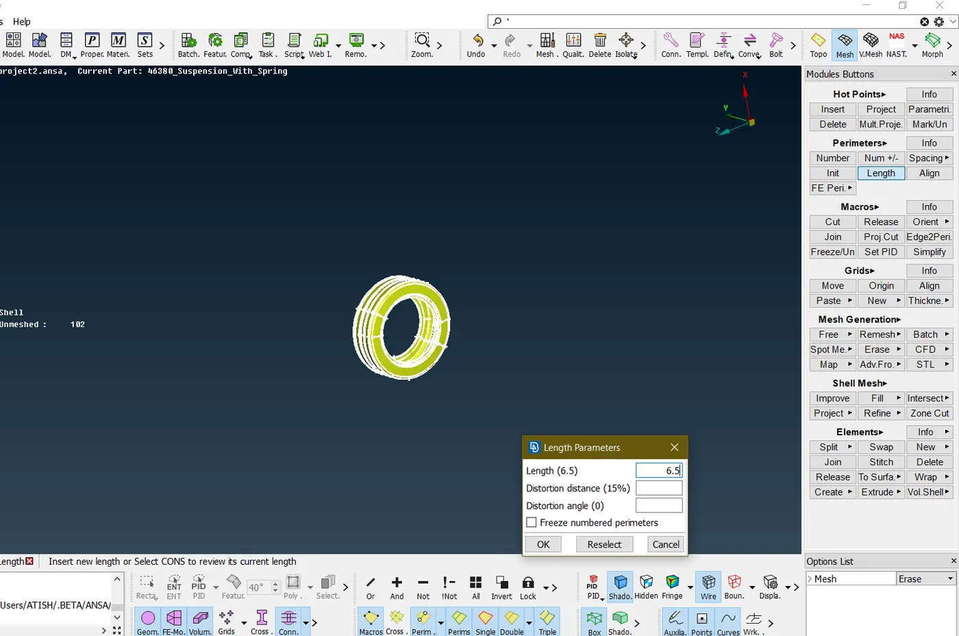
Fig 6- changing the average for the tire to 6.5
Next is to mesh the part using the tria elements and solving the minimum and maximum errors, if generated on the surfaces.
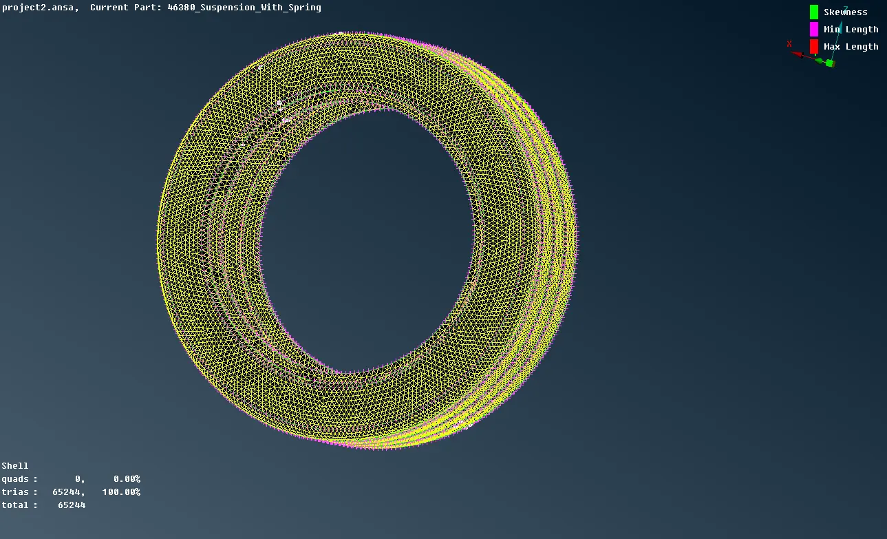
Fig 7- tire shell meshed
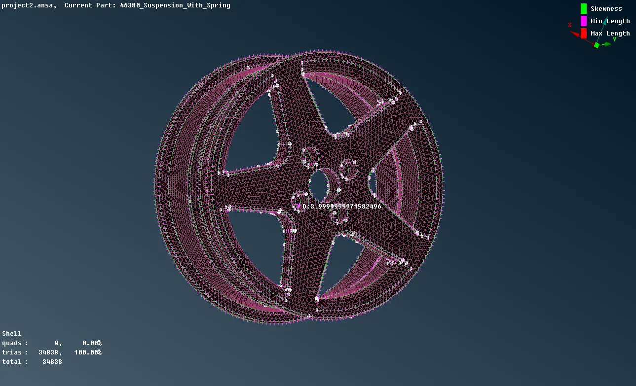
Fig8- rim shell meshed
Proceeding to other regions all the step is followed as mentioned above to perform the shell mesh for the components.
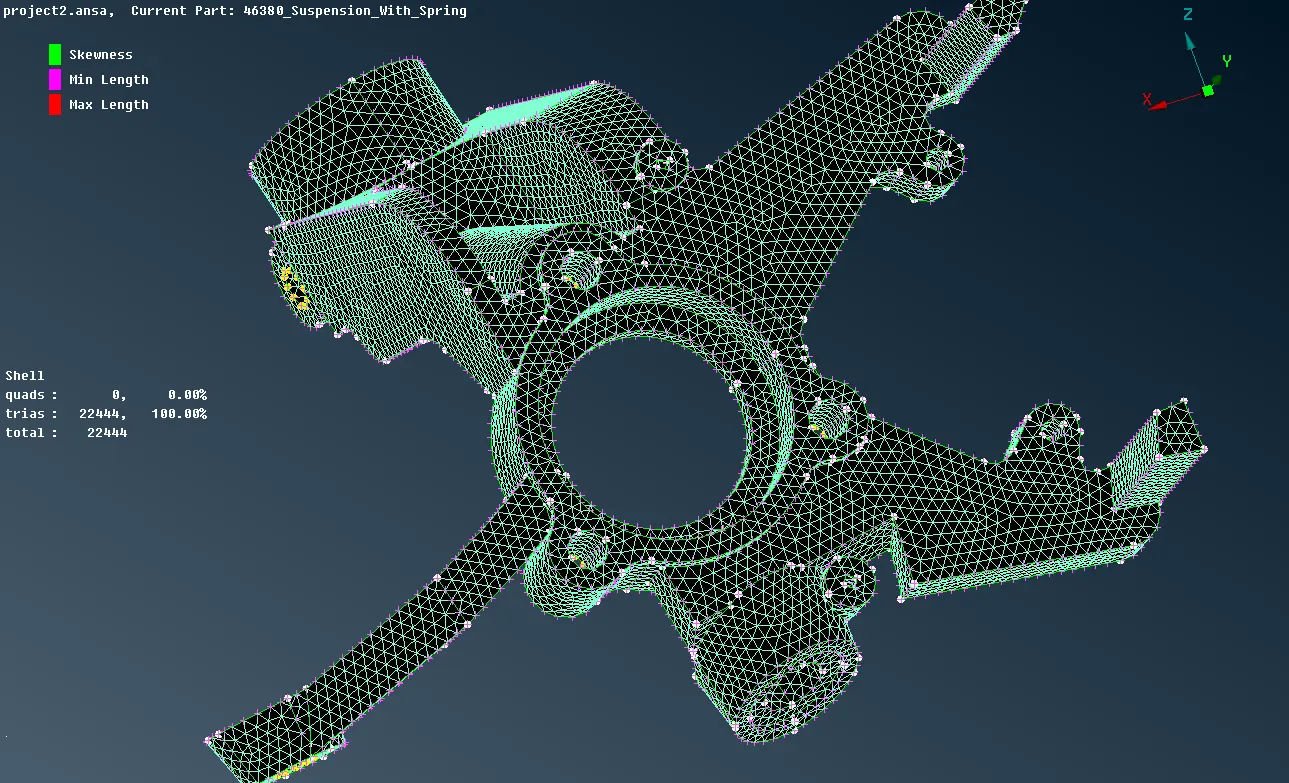
Fig 8- knuckle shell meshed
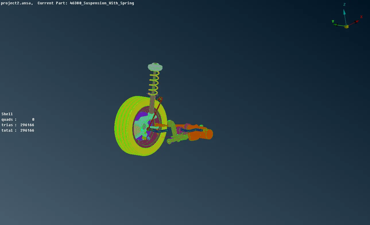
Fig9 – All the tria meshed components
Volume meshing: -
After the component has meshed in a shell, the volume meshing starts with defining these FE or already meshed components as solid (component must be a closed entity).
VOLUME MESH > DEFINE > MANUAL
All the meshed components are defined as volume by creating their PID as solid in the LIST volume. these components are needed to be remeshed as a volume using either of the two methods
- Tetra FEM
- Tetra Rapid
TETRA FEM:
This function automatically creates a Tetrahedral mesh inside selected Volumes. It is to be used mainly for structural applications. Volumes to be meshed with this function must have been defined using the Define (Volumes) function.
TETRA RAPID:
The Tetra Rapid algorithm meshes the Volume with Tetra Elements.
The parameters used during the automatic generation of volume elements are defined in the Options window:
- The maximum growth rate, which is the approximate growth factor of volume element size from layer to layer while the generation moves towards the interior of the Volume.
- Maximum Element Length. Specify the maximum allowable length of the tetra elements to be generated. Useful when specifying a growth rate factor while keeping the length of the elements below a certain value.
Then in the volume list select the component and right-click, remesh using either of the methods.
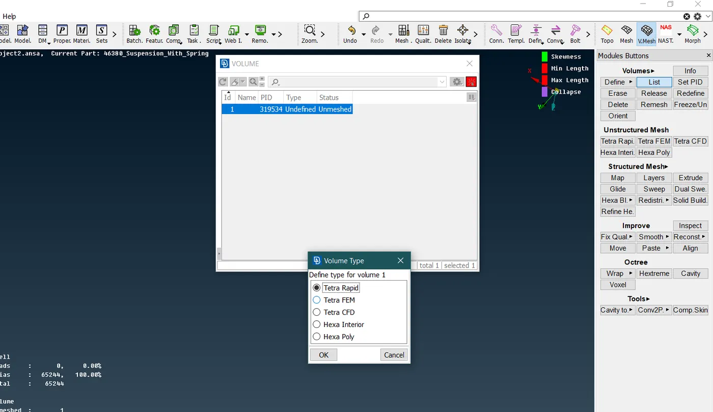
Fig 10- Using tetra rapid for tire
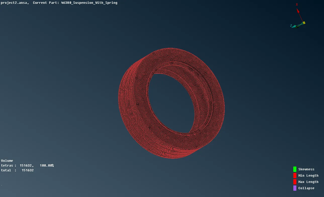
Fig 11- Tyre volume mesh
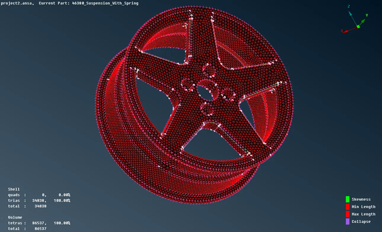
Fig 12 – Rim volume mesh
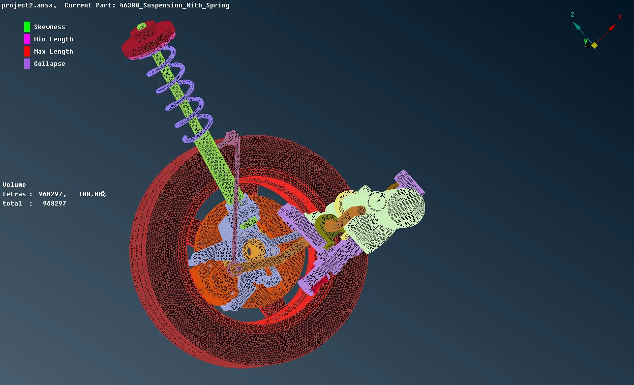
Fig 13- All the components meshed in volume
Errors Solving: -
Split tool:
Most of the errors in the tria meshed can be eliminated using the RECONSTRUCTION TOOL as there are only minimum and maximum length errors are involved. If the errors are not eliminated using the reconstruction tool, we can resolve that individually using the split tool
MESH >ELEMENTS>SPLIT
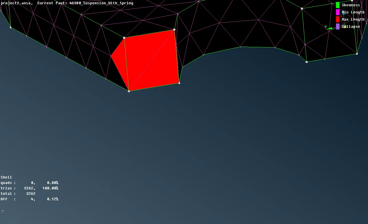
Fig11- elements failing for maximum length
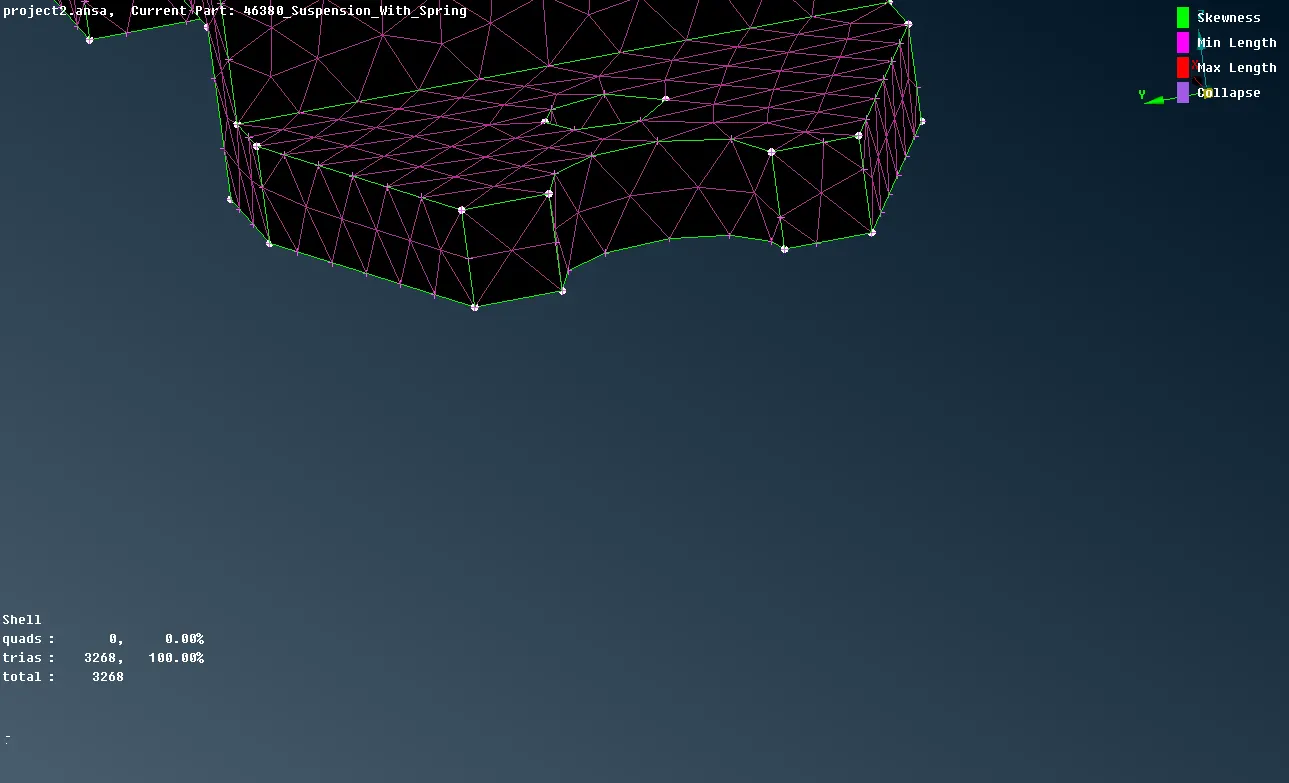
Fig12- elements solved by splitting the trias
In the volume mesh, there is special care taken for the kinks and raised edges. These raised edges are generated either during the reconstruction or during the volume mesh. There tools to remove those raised edges as
- Align
- Move
Align:
Align is quite a handy tool that is used to solve the KINKS and raised edges. These tools simply align all the raised elements to form the continuous smooth streamline pattern.
MESH >GRIDS >ALIGN
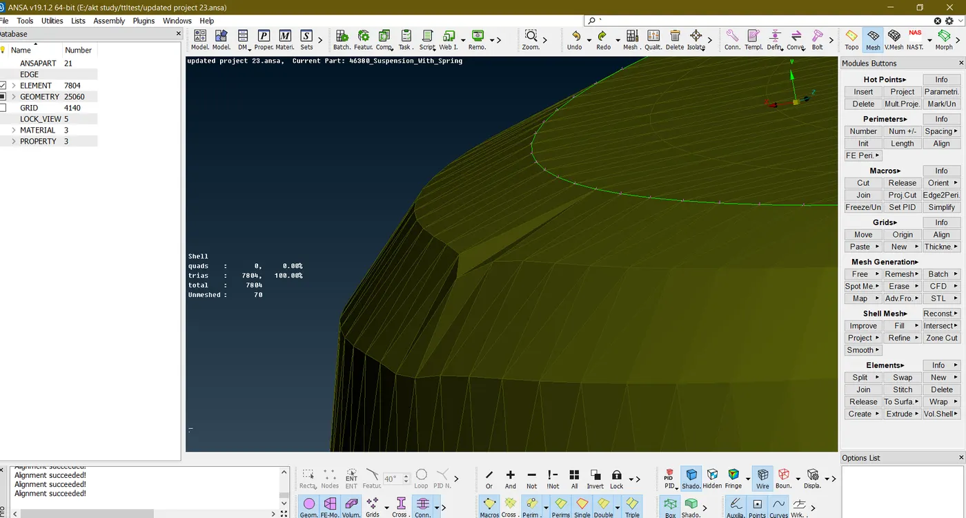
Fig 14- Dips over the surface.
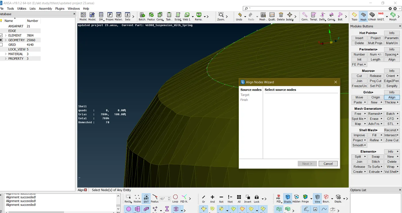
Fig15- Element is aligned
Shell Meshing: -
Since there are some parts in the suspension assembly that are having a uniform thickness, so they can mid surfaced and meshed.
Here the components that are chosen for the shell meshing are quite simple, so they can be easily mid surfaced using the automatic method as CASTING. The reason for using the casting method is that it can extract the mid surface followed by the meshing also it automatically releases the FE from CAD creating its separate PIDs.
Before that, the quality criteria provided for the shell mesh are feed into the ANSA.
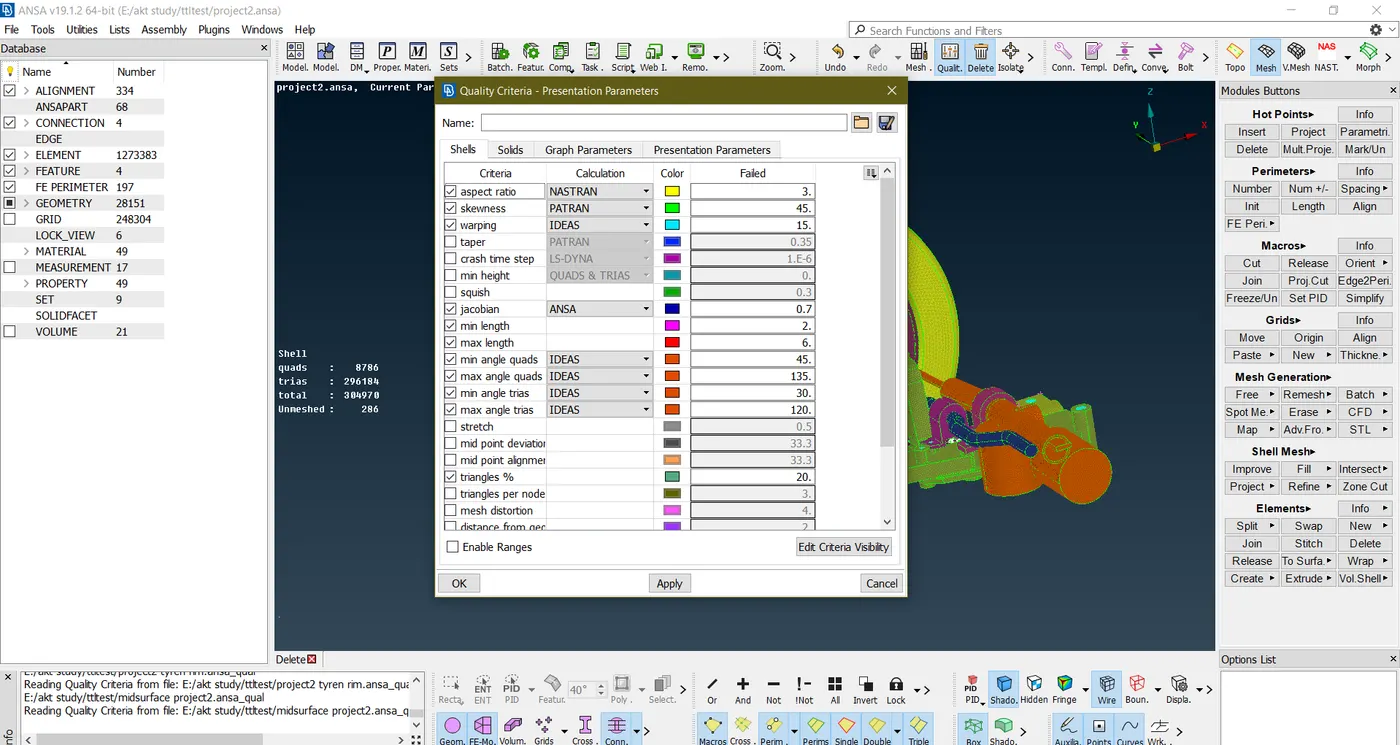
Fig 16- Quality criteria for shell mesh
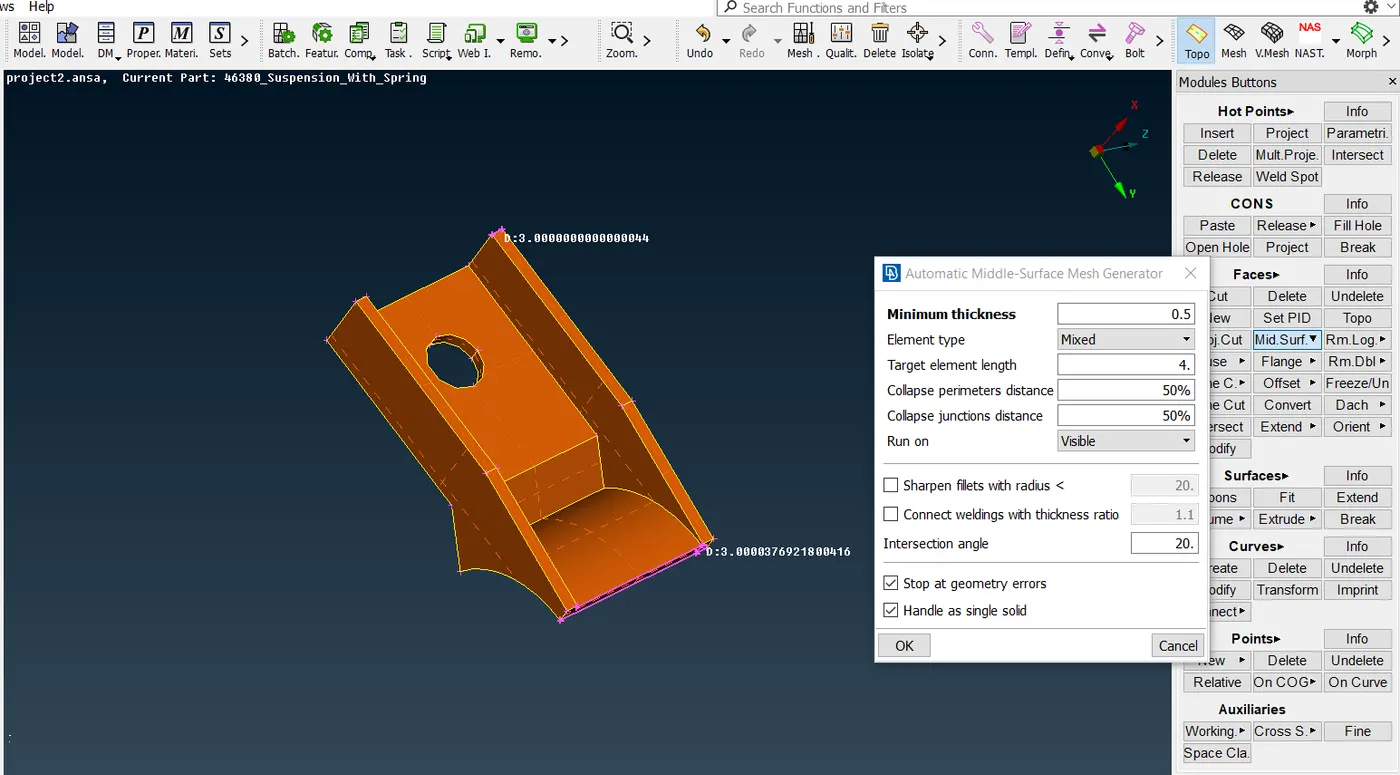
Fig 17- Using the casting method for the bracket.
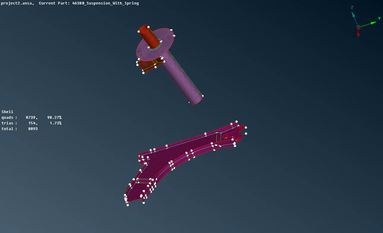
Fig 18 – All the casted components
The errors that are formed in casting can be eliminated using the following tools
- Split
- Cut
- Paste
- Reconstruct
- Smooth
Defining the thickness:
The casting method does most of the work except defining the thickness for the mid surface. That has to do manually in the PID manager so that final mesh can be visualized as solid.
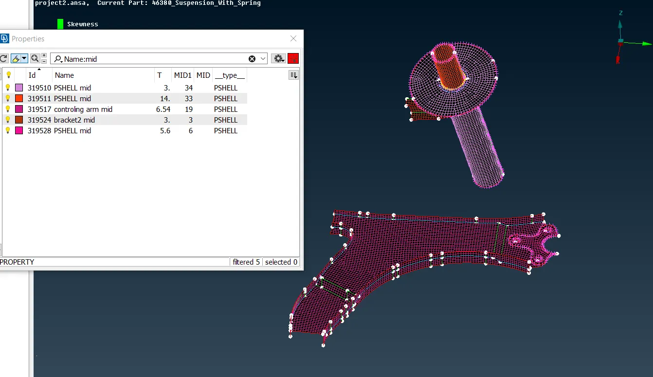
Fig 19- Assigning the PID thickness to mid-surfaced components.
Step 5 – Deploying the Connections:
Why do we need connections?
Rigid body elements are used to create connections such as representing a bolted connection. Modeling a bolt is complicated, and in many cases, it is known from experience that the bolt never fails under conditions we are simulating it for. Therefore, a web of rigid elements is connected to the bolt holes. These elements, in fact, will not deform as they are considered to be infinitely rigid (diamond under atmospheric pressure for example even though it's not infinitely rigid) and the sole purpose of these elements is to transfer the loads between the grid points or nodes.
In the suspension assembly, there are temporary connections i.e. nut and bolts, screw and nut because for the overhauling purpose in case needed.
RBE2 many and 2 nodes:
RBE 2 is a multipoint constraint having a master node (independent node) and several slave nodes (dependent nodes). RBE2 transfers the loads in such a way that all the slave (dependent) nodes have zero relative deformation after the load application. RBE 2 induces stiffness to the joint.
RBE 2 NODES are generally used to rigidize the connection between two components. they are mostly used in nut and bolt connections.
Advantage of RBE2 MANY NODES over RBE2 TWO NODES:
- The RBE2 many nodes are that connection when the load is applied to the master node, this load is then equally distributed to the other nodes (slave nodes). While in the case of RBE2 two nodes load is shared to the particular area or point of connections.
In the suspension assembly hole, regions are rigidized by RBE2 many nodes. While connecting the two parts the RBE2 is used to represent the nut and bolt connections.
Holes area are rigidized by RBE2 many nodes and then the two area master nodes are connected by RBE2 two nodes
RBE2 many nodes – rigid the hole (blue color)
RBE2 two nodes – represent the stem of the bolt (yellow color)
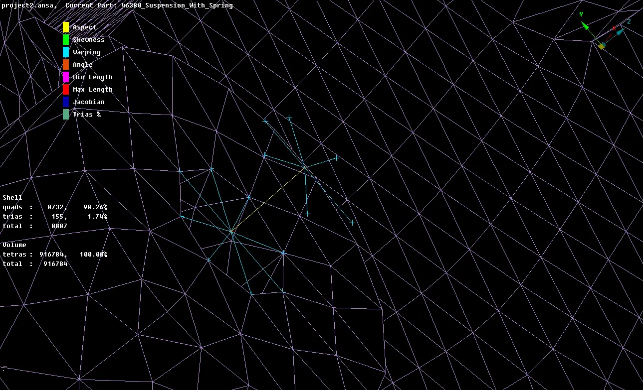
Fig 20 – RBE2 connection to represent the bolt
Automatic bolt connection: -
The ANSA has the provision to deploying the connection automatically
Bolt connections are temporary connection as they can be removed easily anytime without any damage to the component.
To deploy the bolt connection first the COG point is created and it is then realized to BOLT
TOPO > ON COG
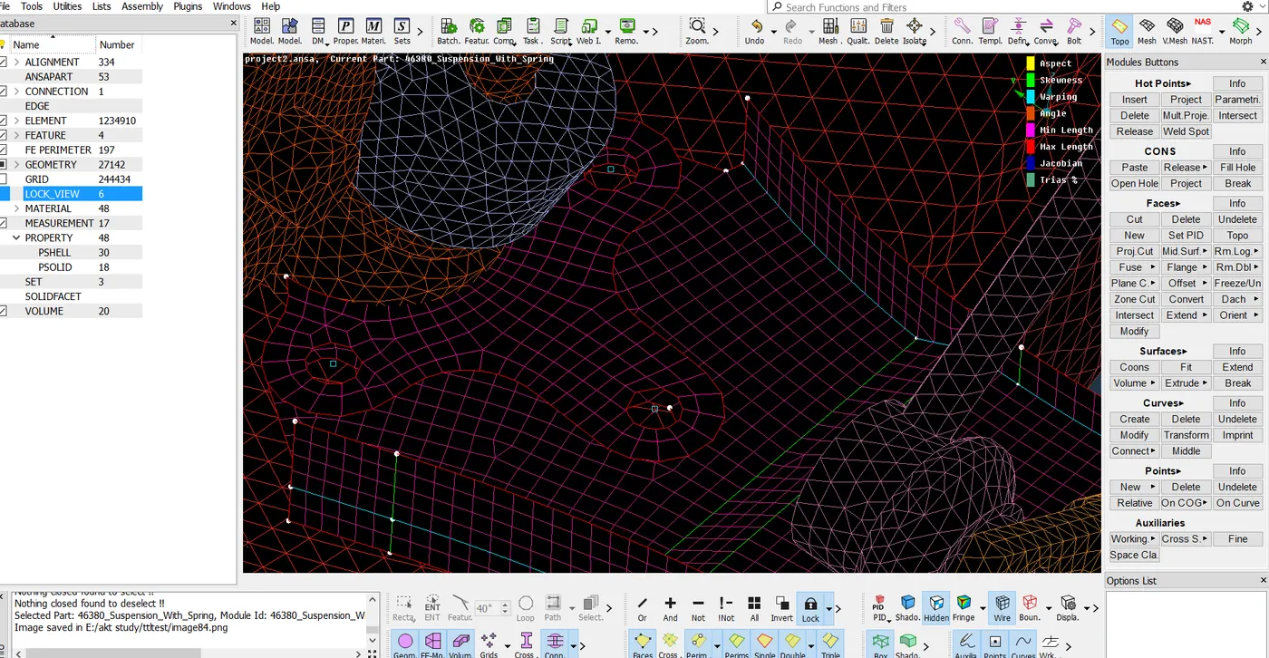
Fig21- COG point is created.
To convert the COG to bolt, go to
CONVERT >3D POINTS >BOLTS
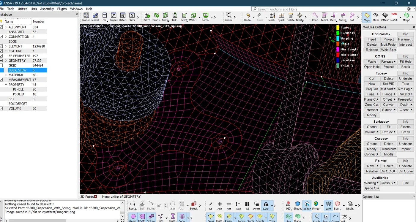
Fig22- COG are converted to bolts
Then the go-to connection manager to deploy the bolt connection. Now the for the positioning of the bolt there are 4 ways
- Inner
- In/out
- In/out x
- Outer
Any of these can be used for positioning, here we are using in/out
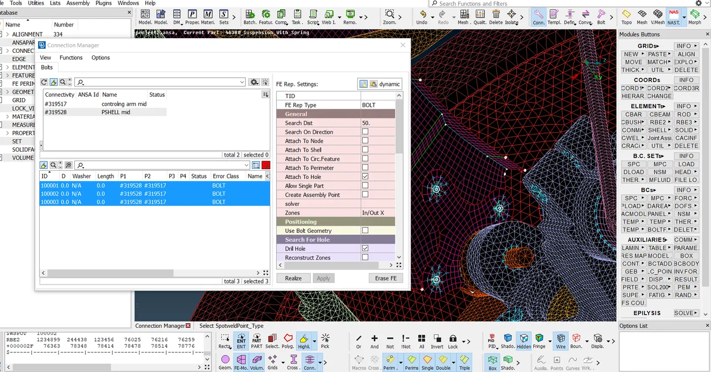
Fig 23- Bolt connection is deployed using IN/OUT X
Like these using all the above-mentioned connection, all connection is deployed to make them rigid.
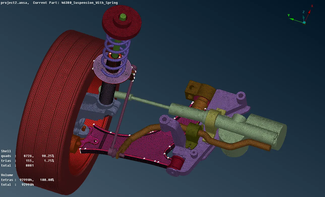
Fig 23- final assembly without connections
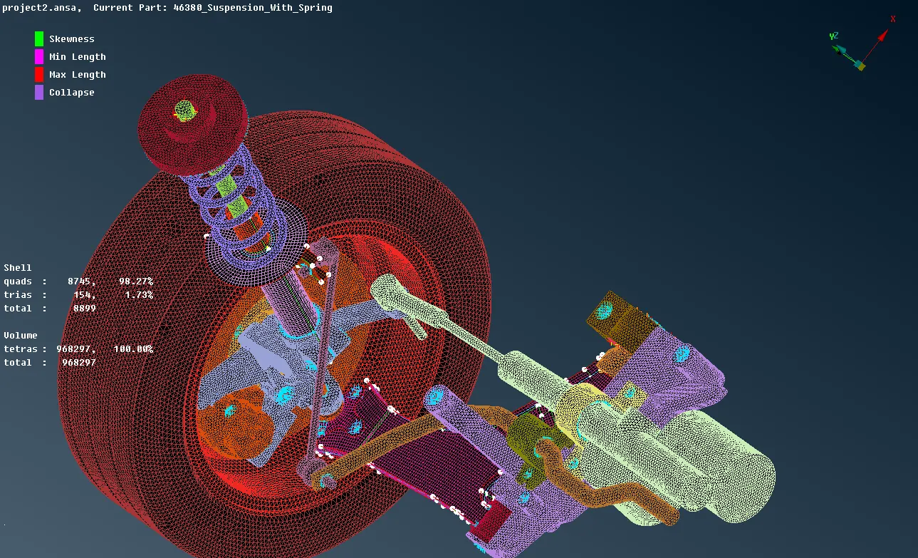
Fig 24- final assembly with connections
Step 6 -TRANSFORMING:
After the meshing is done the available part is only the half portion of the full suspension assembly. In order to have the full assembly, the TRANSFORM tool can be used to mirror the available assembly by symmetry.
TRANSFORM > COPY> ENTITIES > SYMMETRY
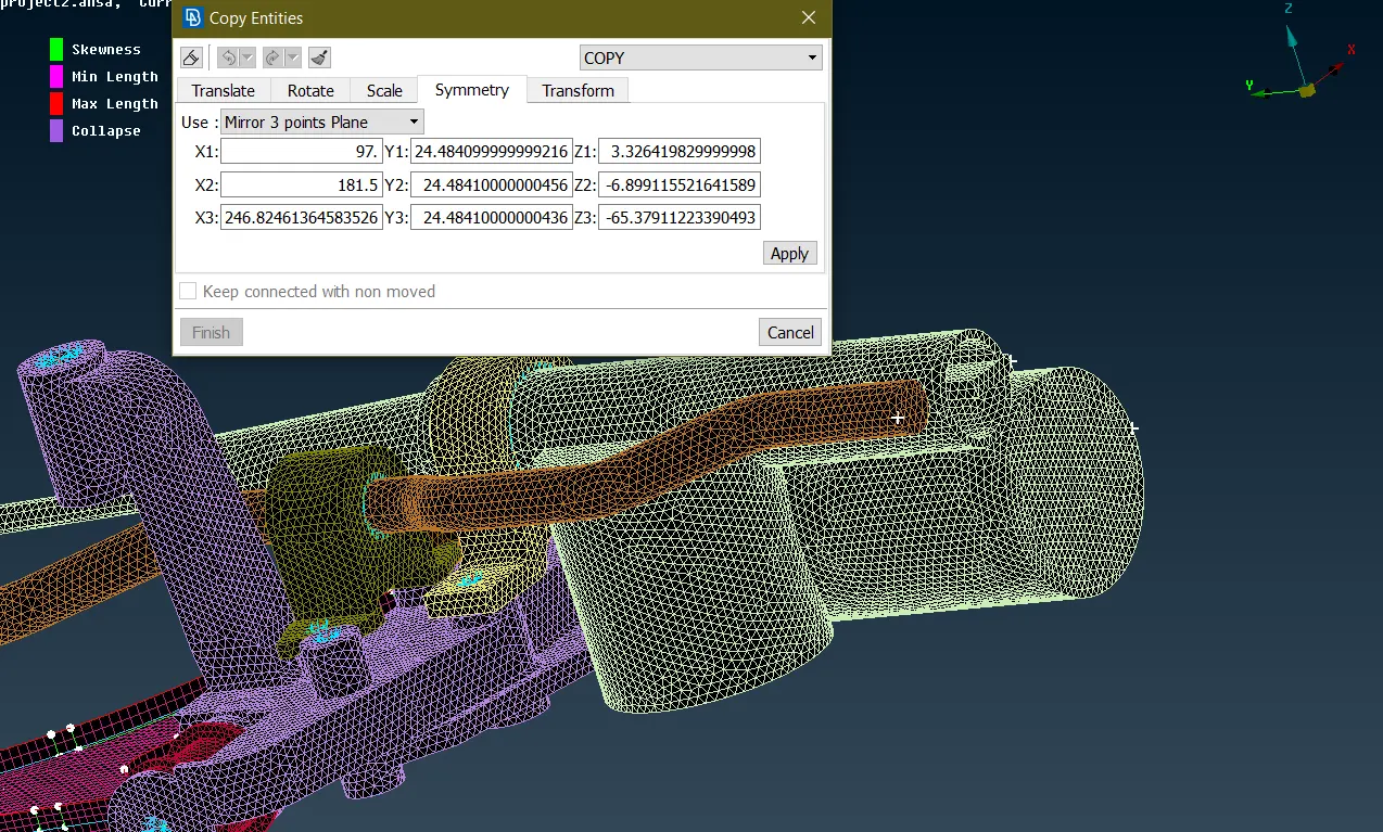
Fig 24- Defining the plane by 3 points.
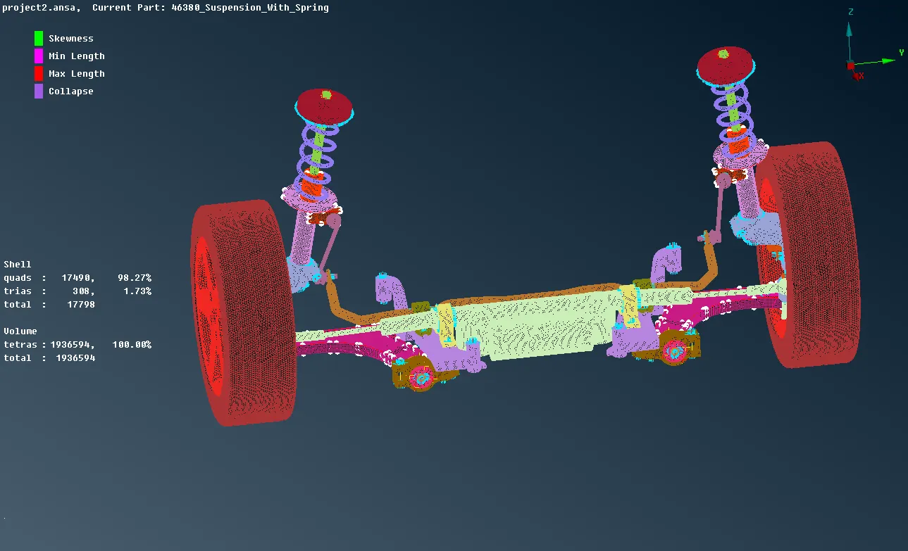
Fig 25- The final suspension assembly after transform
LEARNING OUTCOMES:
- Learned to fix the geometrical errors
- Learned to extract the mid surface for the uniform thickness component by casting and manual methods.
- Learned to perform the tria shell mesh
- Learned to fix the errors in the mesh using various tools.
- Got the idea about the errors in the volume mesh and how to fix them.
- Learned about the TETRA FEM and TETRA rapid.
- Learned to defeature the area in order to avoid errors in meshing.
- Learned to fix the dips and kinks in volume mesh.
- Learned to deploy the connections using the RBE2 many and two nodes.
- Learned to mirror the component using the TRANSFORM tool.
CONCLUSIONS:-
Therefore whole suspension assembly successfully meshed with 2D and 3D elements followed by the connections in the region that needs to the constraint. In this assembly, there were no TET collapse in volume mesh but we have an idea of how to resolve those errors.
Link for the model:- https://drive.google.com/drive/folders/107Lz6dxQ8rhQMKJEXTOoo88sD4kHI4LD?usp=sharing