Project 1 - 2D meshing on the instrumental Panel
Objective:
For the given component, check for the geometrical errors and mesh with the given element Quality criteria. After meshing the component, the thickness has to be assigned.
Write a detailed report on your meshing process and also mention which method you used to extract the mid-surface along with the reason.
|
S.No |
Quality Criteria |
Value |
|
1 |
Target/Average length |
4 |
|
2 |
Minimum Length |
2 |
|
3 |
Maximum Length |
6 |
|
4 |
Aspect |
3 |
|
5 |
Warpage |
15 |
|
6 |
Skewness |
45 |
|
7 |
Jacobian |
0.7 |
|
8 |
Minimum Quad Angle |
45 |
|
9 |
Maximum Quad Angle |
135 |
|
10 |
Minimum Tria Angle |
30 |
|
11 |
Maximum Tria Angle |
120 |
|
12 |
Tria Percentage |
15 |
Procedure:
- Import Model
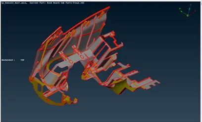
Open the given model (Ip_Console_Half) in ANSA
- Geometry Clean-up
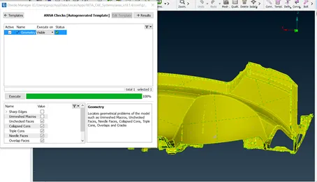
The components are checked for geometry clean-up using Checks > Geometry and clean up the errors using auto fix and use topo tools like new face, delete and topo, etc. to achieve 100%.
- Mid – Surface Extraction
Since the thickness of each part of the component is different, the mid surface of the component is to be extracted manually part by part accordingly.
Below are the tools are used to extract the mid surface
Offset (topo-faces-offset)– parts that have the same thickness for the main substrate (0.6)by offsetting 0.3
Middle -single/multi (topo-faces-middle) – parts that have varying thickness.
For Ribs, we use middle (topo-faces-middle), and then it is extended (topo-faces-extend)
Intersect (topo-faces-intersect) option is also used for the surfaces to intersect accordingly without errors.
Curves – Con2curve & Middle used to extract the curves of the outline of ribs and dog house.
Mid Surface Image :
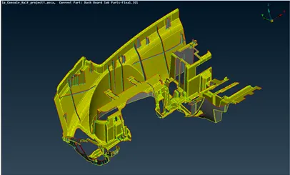
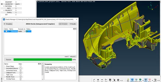
Also, Geometry is checked for errors.
- Assigning Thickness
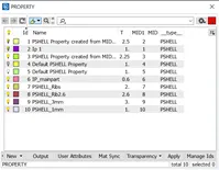
Set thickness (Topo-faces-Set PID) to the mid surface parts accordingly by measuring the thickness of the parent component.
- Meshing
The Mesh parameters and Quality criteria as per requirement are set.
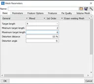
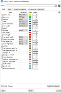
Perimeter and macros are set for 4mm using the length in the perimeter option of the mesh tab.
Each Face(macro) of each component is meshed using the Best option in the Mesh Generation.
Mesh Quality is improved using reconstruct option in Shell mesh.
Further failed elements and trias are removed using Split, Swap, Join (Elements Tab), Smooth (Shell mesh tab), Paste (Grids), and Num +/- (perimeter tab).
We can also use batch meshing.
There might be some Failed elements near Triple CONS or at smaller regions that are bounded by two Triple CONS.
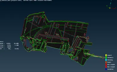
Final Model Image:
Learning Outcome:
To extract Mid Surface of major complex component with varying thickness and meshing it
Conclusion:
The Given Instrumental Panel Substrate component is successfully meshed as per the quality criteria.