Meshing the Plastic Trim Dashboard of the Automobile for FE Analysis using 2D Shell Mesh using ANSA
AIM - To perform 2D meshing on the dashboard Panel for FE Analysis
Objective -
- To check the geometry for the geometrical errors.
- To mesh the instrumental panel.
- To clear the quality errors after meshing the geometry.
Introduction -
#Instrumentation Panel -
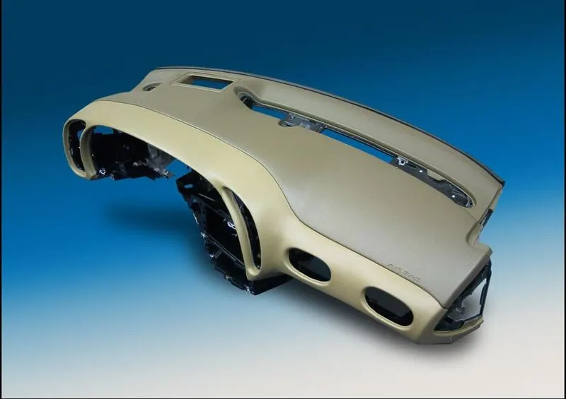
fig - Dashboard Panel in Automobile
Dashboard Panel in automobile is one of the important component made of plastic. The main objective of instrumentation panel is to hold on all the supporting components like Speedometer, Glovebox compartment,, Music system, Windsheild Wiper Control, Airvents, etc.. Dashboard Panel is one of the most complicated structure in automobile. Its design and complexity helps one to understand its need and important of all the features.
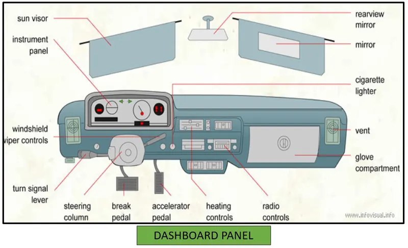
The function of Instrumentation panel or dashbord panel is very critical and therefore it is very important for the analysis engineer to analyze the components of this types. One of the finest analysis which is carried out on the dashboard panel is NVH analysis. As the vehicle has to go through the different road condtions the passeger can feel the vibration of the panel. So to make these vibrations as low as possible and to serve the comfort feeling to the passengers the study and analysis of dashboard panel is very important from industry point of view.
Here the user perorm the 2D meshing on the dashboard panel to show how typical the design of dashboard is and how the FEA Engineer approach it to make it perfectly mesh for analysis purpose.
Stepwise procedure explained below will help to understand the meshing and approach.
Procedure -
Step I - Import the geometry i.e, .ansa file (extension) using the file tab in the ANSA window.
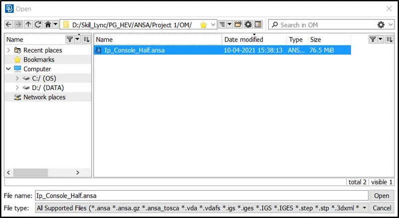
fig - Importing file in ANSA
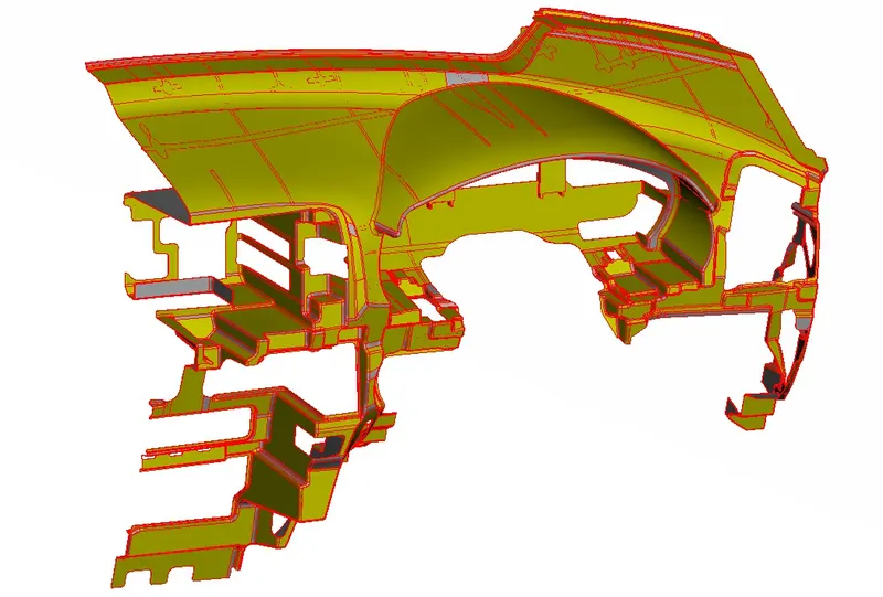
fig - Imported Dashboard Panel
Here we can see the panel with yellow and grey color orientation with red color edges. The red color edges indicates that they are not joined and need to perform topo which will join all the edges as shown below
Step II - Performing the Topo on the Geometry
Before performing the topo operation the user makes sure the egdes remain fine. For the the perimeter and the macros lenght is set to 1 mm.
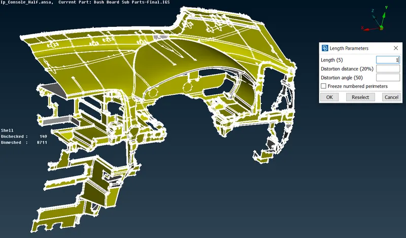
fig - Perimeter Length Change
After changing the length of the perimeter the user user Topo Button in the topo module to join the edges as shown bwlow.
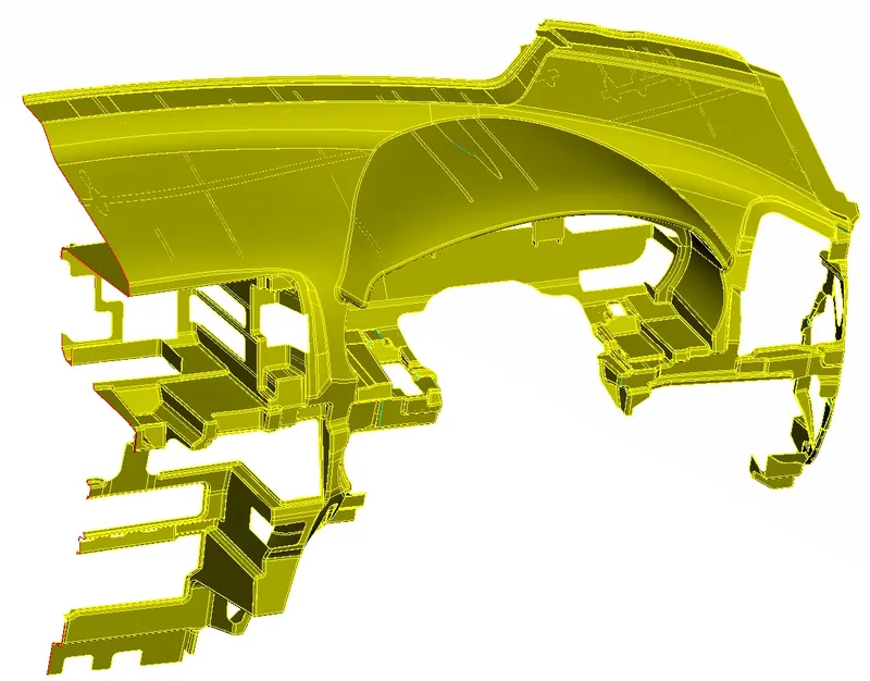
fig - Performing TOPO
Step III - Check the geometrical error using the check manager
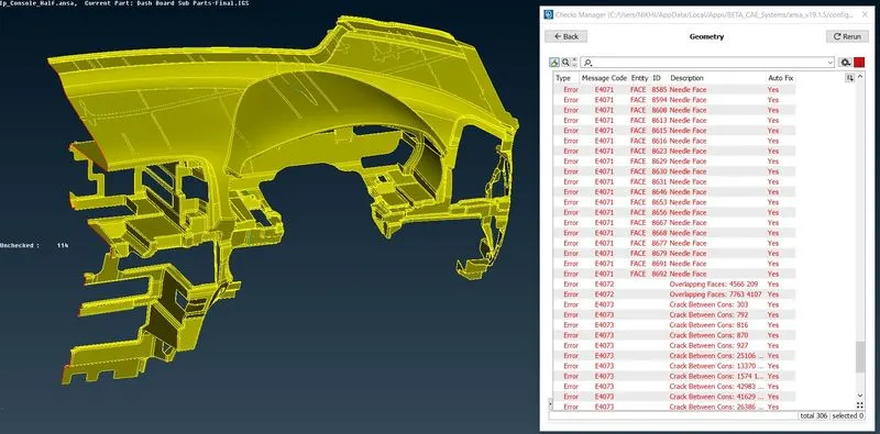
fig - Performing Geometry Check
After checking for geometry, we get the following errors in the geometry. There were needle faces, triple cons and crack errors, Ovalap Surfaces and Unchecked Faces in the geometry. This needle face error is nothing but the unwanted faces in the geometry which needs to be cleaned up. Triple Cons errors are cleaned using releasing the two surfaces and performing proper topo. Crack is fixed by using new a face. Overlap Surfaces are cleaned by removing the overlap surfaces.
After clearing all the errors in the geometry there is no error after performing geometry check-up.
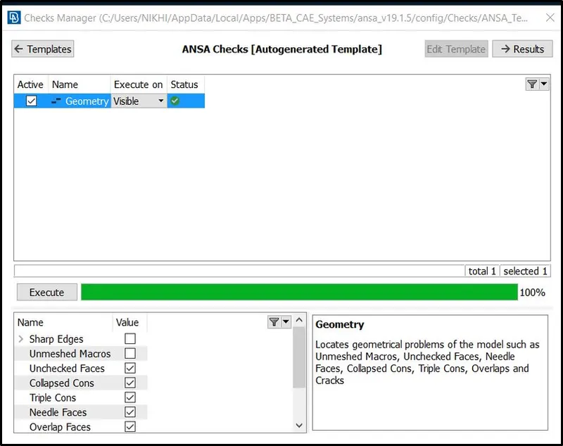
fig - No Error after the geometry topo cleaned up
After geometry clean-up we check for the thickness measurement of the various surfaces and extract the mid surface using various options.
Step IV - Extracts mid surfaces of the components using offset, middle & curve middle command.
Thickness measured for various sections and mid surface is extracted using above command. Some surfaces where it was impossible to extract the mid surface due to unavailability of opposite faces there new surface is created using curve middle command and new faces option also some surface have been extracted using approximate / nearby thickness.
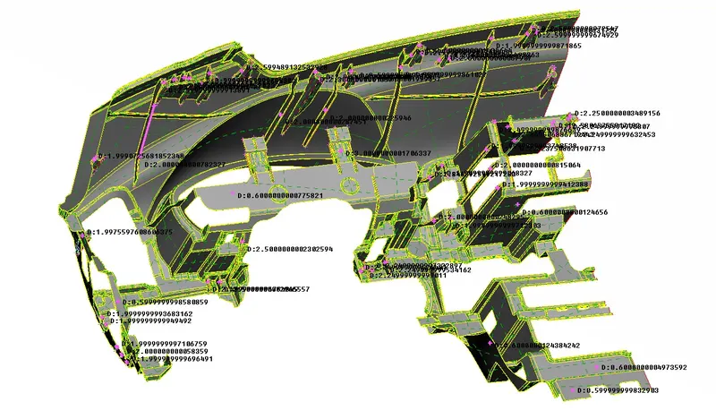
fig - Measurement of thickness for various surfaces
Extractef Midsurfaces
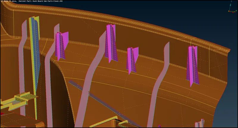
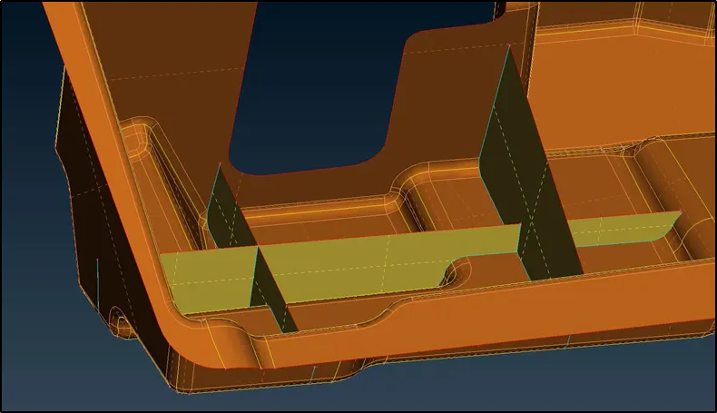
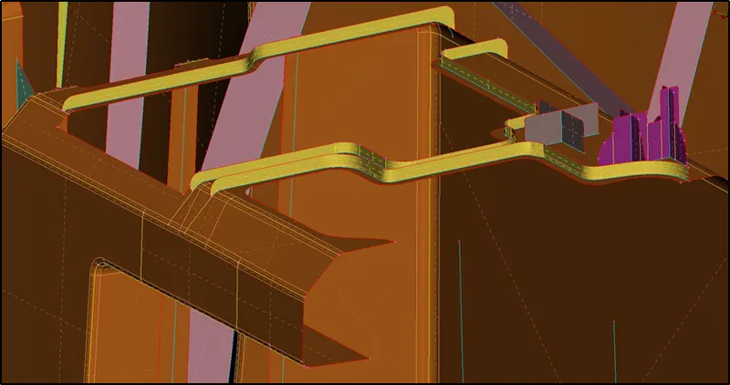
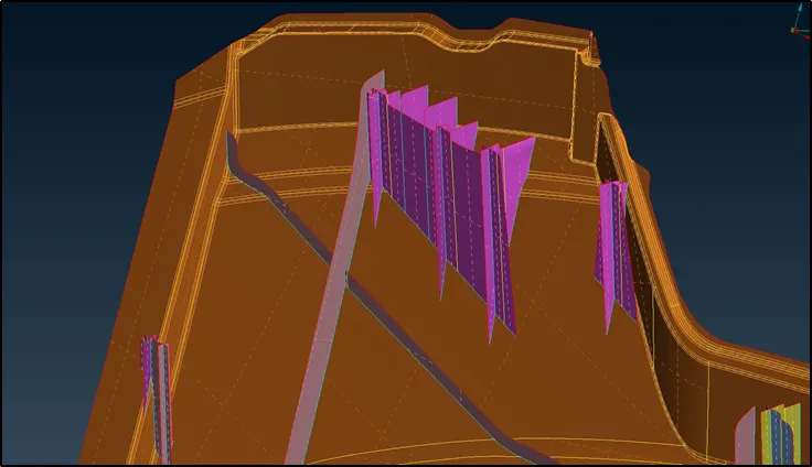
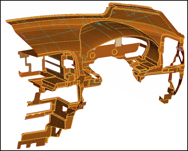
After extracting the mid surfaces each surface had been assigned separate new PID and respective thickness.
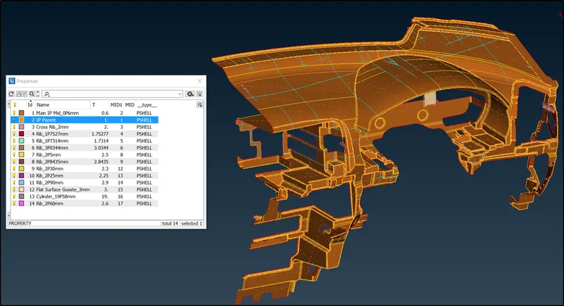
fig - PID's Assignment with respective thickness
Step V - Meshing the geometry using Mesh Module
Before meshing the modules, we assign perimeter & macros length as target length and mesh parameter and quality criteria as below,
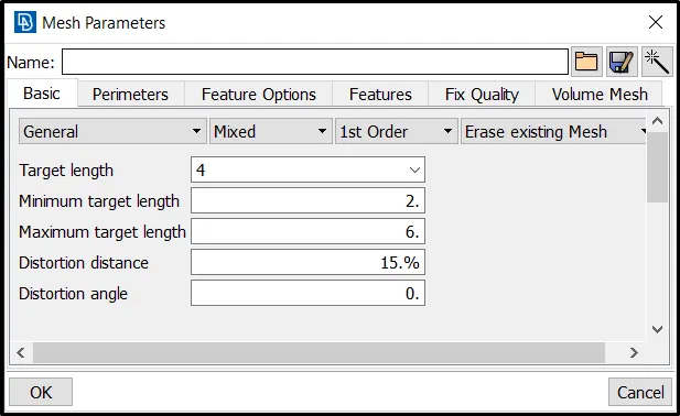
fig - Mesh Parameters
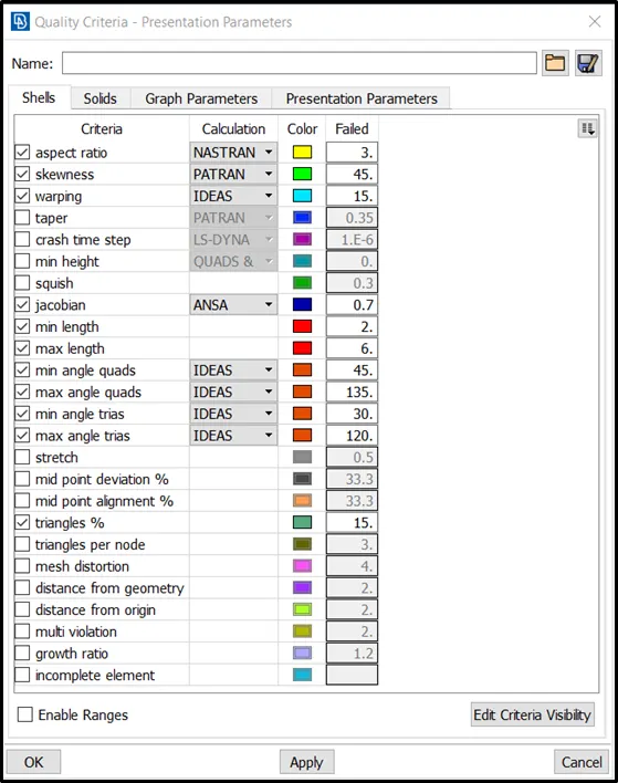
fig - Quality Criteria
After this, geometry is meshed using best command in mesh generation tool and with the help of various others commands like reconstruction, smooth, paste, split, swap, join, etc and mesh is obtained as shown below,
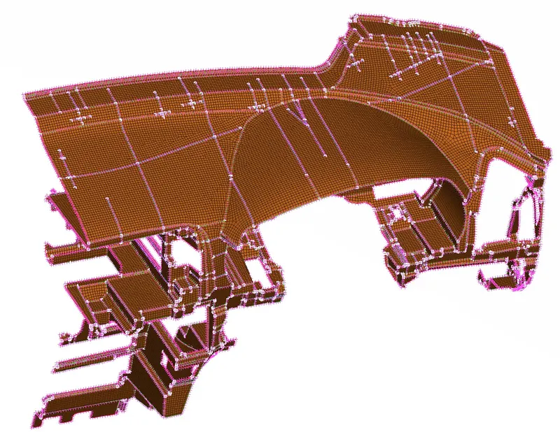
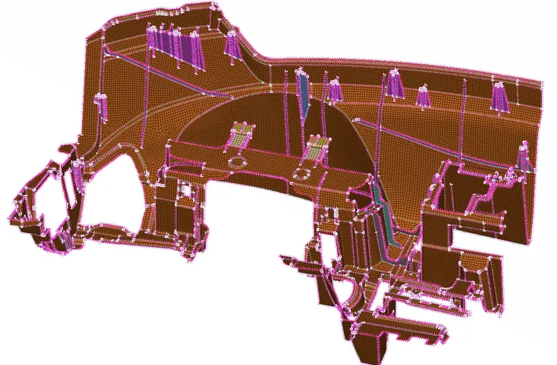
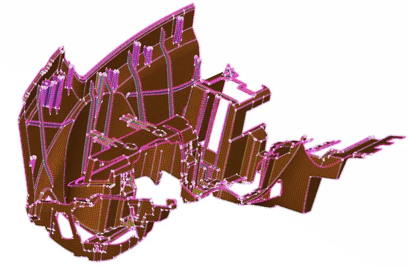
fig - Mesh Generation Complete
After obtaining the mesh for all the PID we draw the shell as solid which can be seen in the below screenshots,
To draw the shells to solid under the presentation parameter in the quality criteria there is option to make the shells as solid as shown,
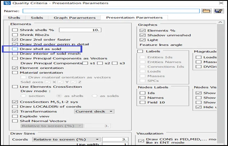
fig - Activating shell to solid option
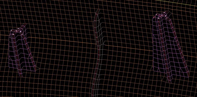
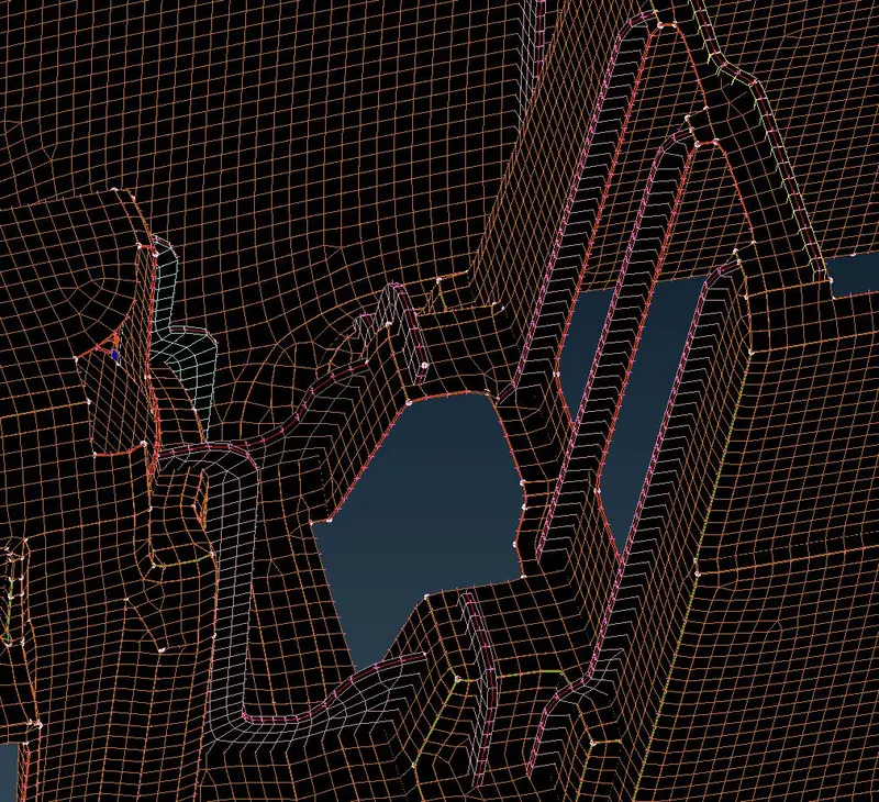
fig - Solid Shell Part
Learning Outcome -
1] Extract the mid surfaces for critical plastic parts.
2] Extraction of mid surfaces for joint ribs.
3] Curve Middle - This command can be used to obtain the middle of the two surfaces and then generate the mid surface.
Conclusion -
Here user can conclude that the Instumentation Pane; is successfully meshed after the geometry topo clean up. Some elements were unable to acquire mesh quality as per given quality criteria and failed to gain the feature due to minimum length, skewness which can be improved at the further stage before final analysis of the model.