Project 1 - 2D meshing on the instrumental Panel
AIM: To extract the mid surface of the Dashboard panel with certain quality criteria with Proper mesh flow.
Objective:
Extracting the mid surface of the Dashboard instrumental panel with proper mesh flow with proper quality criteria file.
Introduction:
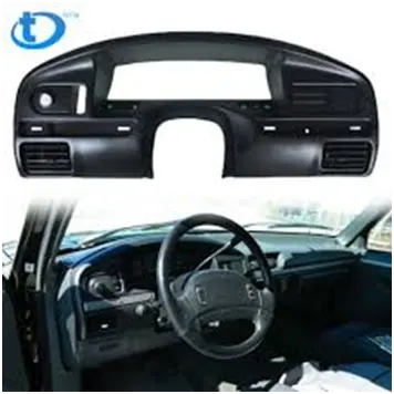
The instrument panel of a vehicle is the panel where the dials and switches are located. The trip computer readout is mounted on the instrument panel of the car. The instrument panel is a cluster of gauges and switches that is mounted on the driver's side of the dashboard.
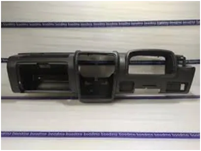
Dashboards may include the speedometer, tachometer, odometer, engine coolant temperature gauge, fuel gauge, turn indicators, gearshift position indicator, seat belt warning light, parking-brake warning light, and engine-malfunction lights.
CAD Model:
Import the model into ANSA GUI
Performing Topo / Geometry clean-up on the given model:
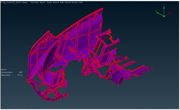
The image shows the isometric view of half portion of the Instrument Panel
- The resolution of the part is defined by the distance between the adjacent hot points on the perimeter and macros. The resolution is low by default. To get a refined view of the part, the resolution is increased using the MESH -> Perimeters -> Lenght function. In the selection window, Perimeters and Macros are selected one by one and in the length field, the value is set to 1 mm.
- When the adjacent faces are not connected to each other, the edges of the face are represented by single cons (red lines). The surfaces are connected using TOPO -> Faces -> Topo function and selecting the whole part. On confirmation, doubles cons (yellow lines) are formed and faces get attached.
GEOMETRY CLEANUP:
Geometry is checked using Menu bar -> Tools -> Checks -> Geometry -> Execute. In the template, all the geometric failures are ticked and the check is executed. The check manager shows all the encountered errors:
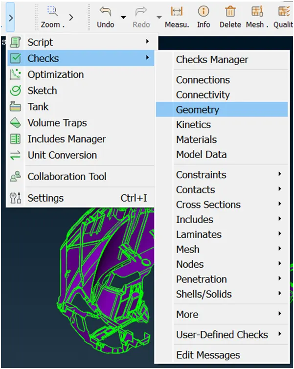
Click Execute to perform the cleanup
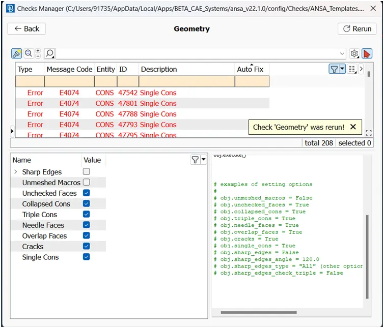
All the errors are selected and fixed automatically using right-click > Fix function
The checks manager is rerun and unchecked faces and collapsed cons appear as errors. Since these errors were not fixed automatically, they are fixed manually. The errors are found by using right-click > Show only. The neighboring entities are made visible using Menu bar > Focus > Neighb
All the unchecked faces are deleted and reconstructed using TOPO > Faces > New function.
After manually clearing out the geometrical issues, the following result is obtained:
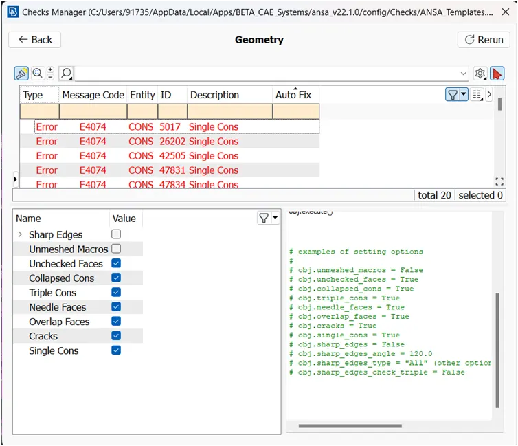
Once doing the geometry cleanup manually, now we have to extract the mid surface for the model
Extracting of Mid surface:
Mid-surface is the representation of the whole CAD model without thickness. It captures the whole component with all the features on it in a single layer surface.
The mid-surface can be automatically generated in a go using the Skin and Casting option available in TOPO > Faces > Mid. Surface
The skin method is used for the whole component and the following result appears:
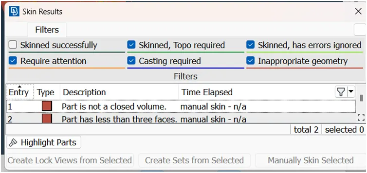
It shows that ANSA could not skin and it suggests the Casting method. It says that geometry is inappropriate since the part is not closed volume. As the part is cut in half, it is not a closed volume, hence it cannot be skinned.
The casting method suits the best plastic parts (having variable thickness). Since the part has complicated geometry (having ribs, fillets, and dog houses) Casting function is not preferred. The casting method fails to capture the complicated geometry and generates a lot of failed elements.
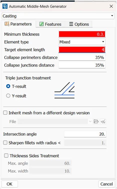
But Still dog houses are also present, we can still go with the Casting method due to ALIGN MANAGER option.
Once extracting the mesh in the model we have to perform quality criteria as per the given criteria file.
|
S.No |
Quality Criteria |
Value |
|
1 |
Target/Average length |
4 |
|
2 |
Minimum Length |
2 |
|
3 |
Maximum Length |
6 |
|
4 |
Aspect |
3 |
|
5 |
Warpage |
15 |
|
6 |
Skewness |
45 |
|
7 |
Jacobian |
0.7 |
|
8 |
Minimum Quad Angle |
45 |
|
9 |
Maximum Quad Angle |
135 |
|
10 |
Minimum Tria Angle |
30 |
|
11 |
Maximum Tria Angle |
120 |
|
10 |
Tria Percentage |
15 |
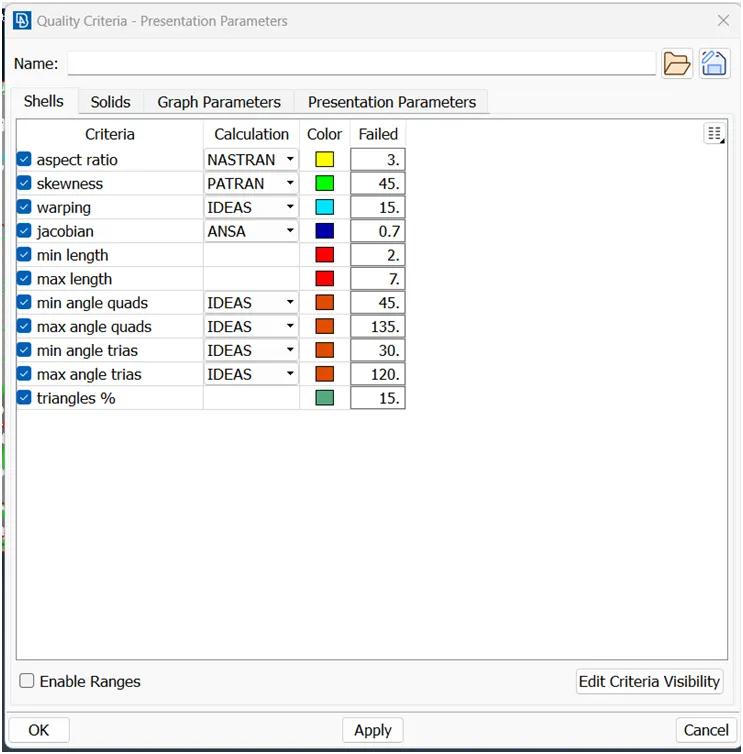
Performing Element cleanup:
The Off elements are the elements that are failing for the quality criteria
These elements are manually tried to be fixed using functions like MESH > Shell Mesh > Reconstruct and Smooth
The trias formed on the free edges and feature lines are removed using the MESH > Elements > Split function.
The opposite trias, the rotating quads, and the adjacent trias are eliminated using the Split function and/or Paste function in MESH > Grids
The quality failures that cannot be cleared using above mentioned functions are tried using the Grids > Move function. this function displaces the grid on the same surface in any direction as cursor movement.
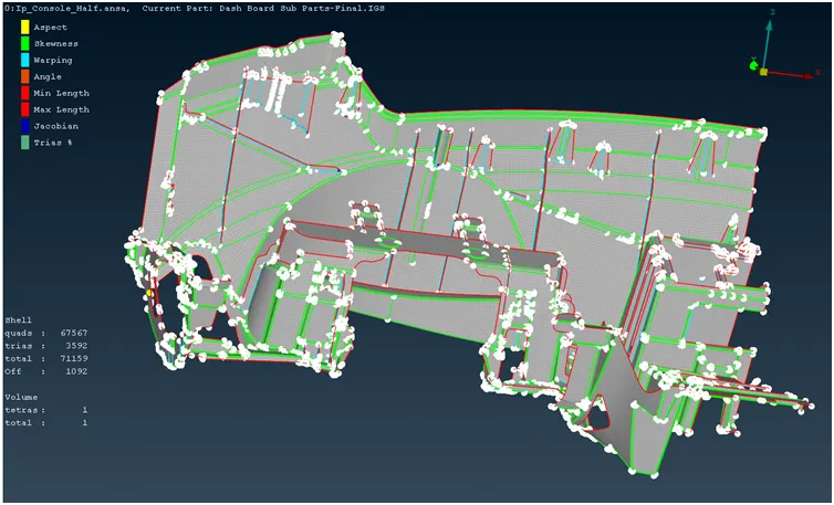
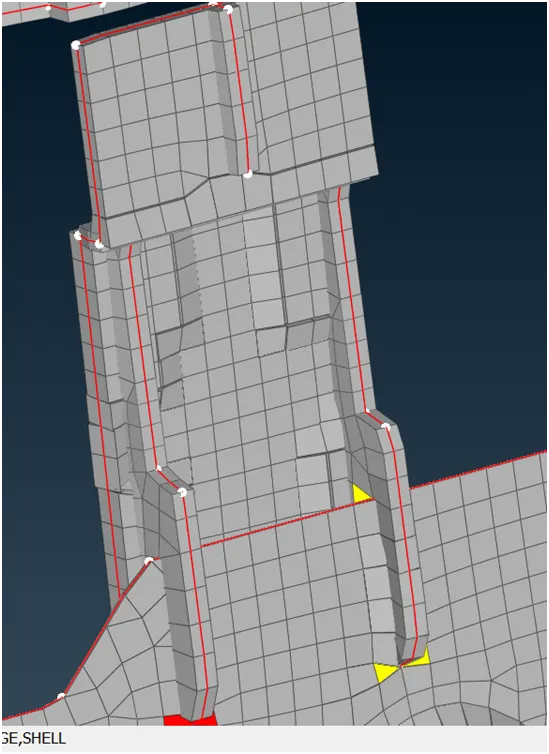
The quality failures are reduced from 2062 to 1092. The off elements could not be removed completely due to the close-lying triple cons and single cons. The triangle percentage is 5.08% which is well below the permissible limit.
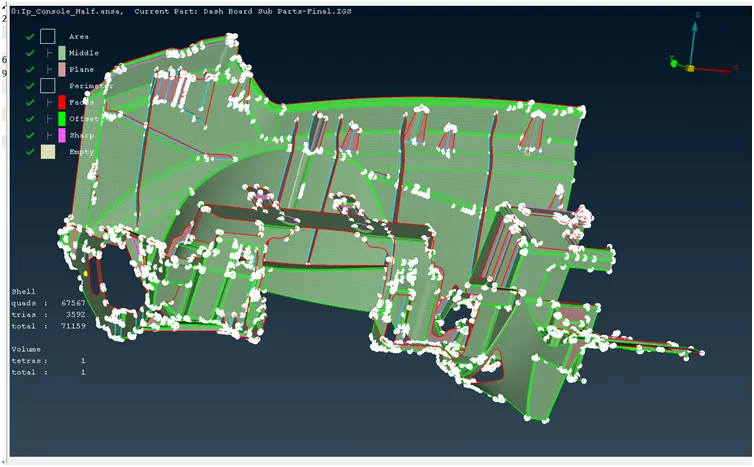
ALIGN MANAGER:
It is a new feature available to perform the mesh flow which is been aligned to the parent geometry, to extract the exact outer structure i of the Parent geometry.
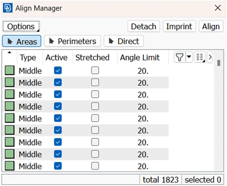
In this align manager we can able to perform with Area, and perimeter, Imprint the parent geometry to the mesh to capture the flow of the mesh.
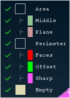
Color is been indicated to sort out the mesh region which comes under different categories.
Capturing all the features in the correct order as per the parent geometry.
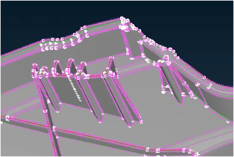
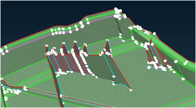
Curves have to capture in proper flow to get as it as:
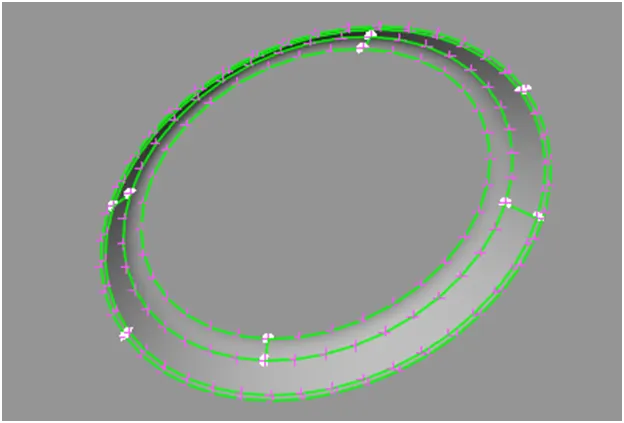
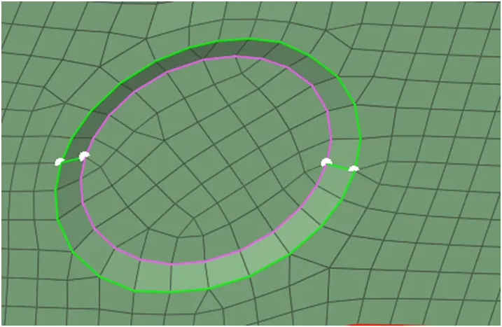
Different areas of the model are mostly captured with the Plane, Middle of the surface
For a plane surface "Middle" option is the best to choose, for the Houses and ribs parts "Plane" option is chosen.
To get a proper alignment as per the parent geometry we have to use imprint, and also we have to rerun the middle or plane option if the surface is been captured unevenly.
To assign Thickness:
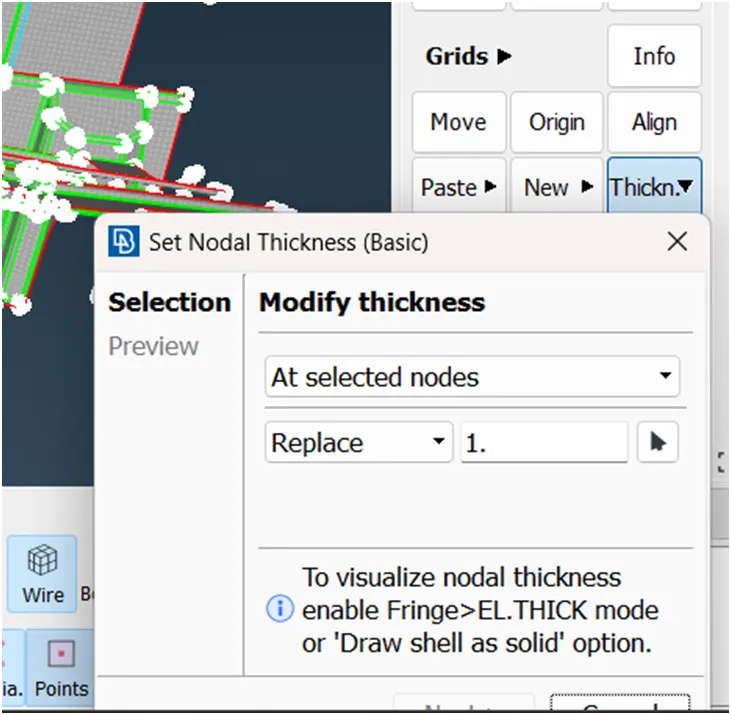
Since we perform Casting methodology to perform the mesh in it, we can able to assign the thickness automatically by following the steps
Classic mesh -> Grids -> Thickness -> Select the entities to assign thickness.
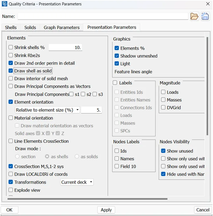
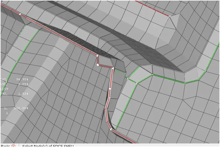
The thickness is enabled for mid-surface FE by enabling Draw Shell as Solid in "Quality Criteria > Presentation Parameters -> Draw shell as solid -> apply".
Outcomes:
When a new face is created using COONs, the adjacent faces do not merge into a single face after suppressing the connecting double con. Whereas when a new face is created using the Existing Surf method, on suppressing the double con, faces merge.
Unchecked faces are usually invisible. Its presence can be determined by turning on the Cross Hatches in the Menu bar -> Faces Draw. Unchecked faces are eliminated by deleting them and recreating new faces.
Conclusion:
As the result, we have performed align manager to get a proper flow of the elements occurring in it, with meeting proper quality criteria limits.