Project 1 - 2D meshing on the instrumental Panel
Aim:- For the given Instrumet panel, we have to perform the 2D meshing by eliminating all the geometrical errors and using the given quality criteria.
Procedure: -
- Basic checks of geometry
- Geometry cleanup
- Mid surface Extraction
- Meshing the Mid surface
- Applying Different PID’s to various thickness regions
- Applying “Draw shell as solid” command
Step 1: -
Basic checks of Geometry: -
- First, we will import the CAD Geometry to ANSA and will check whether the CAD model format is in supportable format or not. Supportable formats are
STEP (*. STEP/ *.step/*.stp/*.STP)
IGES (*.IGES/*.iges/*.IGS/*.igs)
STL (*.stl)
- Second, we have to ensure that the dimensions of all parts in the model, importing in ANSA must be same, and it is recommended to be in mm.
- Most important thing is graphics check. Here we have to ensure that the Hot points and CONS are clearly visible and no problem should be there in visibility. If problem is there, we can put this command “-performance_mode 3”, in the popup box while opening ANSA to get good Graphics.
TIP: - If we need to get Good Resolution of the hot points, do the following
Click F11 >> Go to Presentation parameters >> scroll the bar of “all details” to left >> click on apply
Step 2: -
Geometry cleanup: -
- First, we have to assign the material to the given model without letting any problem to arise further. Here, assigning means nothing but just ticking the box of the created material in MID tab.
- Now, we have to perform checks on the geometry using “checks” Geometry checks are, checking for Single cons, triple cons, cracks, needle faces, collapsed CONS, unchecked faces.
Go to checks >> Geometry >> select checks to be performed >> Execute
- Before Geometry cleanup:
- Errors in Geomentry:
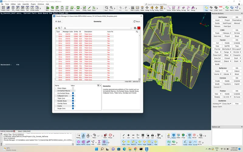
- The above error can be cleared in two ways. Either by going to error by error and dealing with it, or by using the inbuilt ANSA “fix” option for removing all errors at once. I used the “fix” option, as it is easy to use when there are lot of errors and doing manually consumes so much time.
-
Select all the errors using “CTRL+A” >> right mouse click >> click on FIX
-
Sometimes the ANSA might show some errors after some time even after using FIX option, then we have to clear the errors manually. This is the drawback of FIX
-
Manually, most of errors can be cleared using basic release CONS & Hot points, TOPO, paste options etc.
-
After removing Errors In Geomentry:
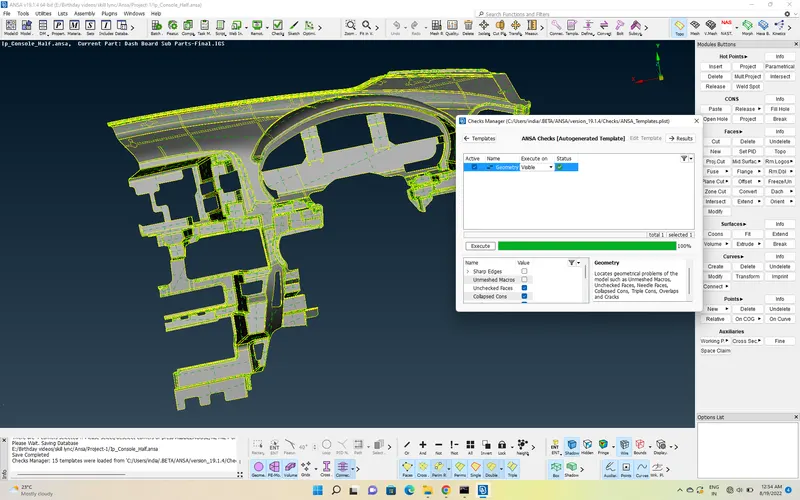
-
Now, we have to do visual check, which means the outer surface or positive surface should be “Grey” and the inner surface or negative surface should be “yellow”.
Using Orient >> visible, we can orient the surfaces.
- we also have to check the entire model, if there are any thickness changes. So, here we will go to feature by feature, surface by surface and randomly measure the thickness.
- Finally, we will check whether the features are correctly placed or not. How we will check?
Go to Auxiliaries >> Fine >> click on the features
Here we will know the true shape and placement of the feature.
Step 3: -
Mid surface Generation:
- Before mid-surface Generation, we have to ensure that we have created different locks for components based on their PID’s. It will be easy for us further, while doing mid surface generation and meshing, component by component.
- We can generate the mid surface in 3 types, either by using “Faces >> offset” or “mid surface >> skin” or "Faces >> Middle ".
- I used all the options together to generate the Mid surface, as it is a Plastic component.
- Mid surface Generation
Faces >> Middle Multi >> Select Multiple faces >> middle click >> ALL(after clicking all we see generated Mid surface)
and
Faces >> Offset >> Give offset value
Mid surface Generated: Here using offset >> select faces option Mid surface is generated
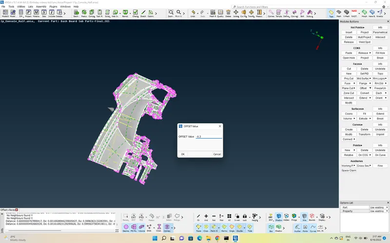
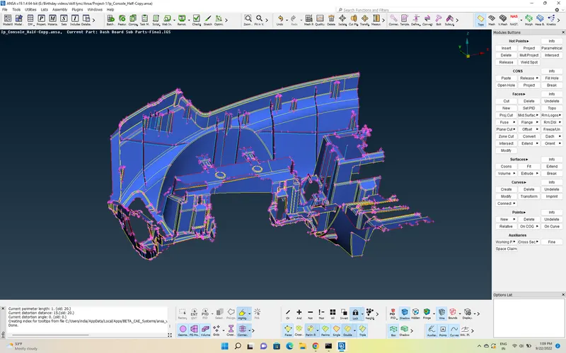
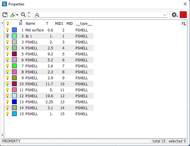
Now, we will assign Different PID's to various features according to their thickness using PSHELL Card.
PID's Created and Thickness assigned:
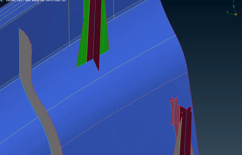
Mid Surface After PID Assignment:
Step 4: -
Meshing: -
- After generating the mid surface and before meshing also, we have to check for the geometrical errors and has to do basic things such as, performing Geometry check, surface orientation. Only after having zero errors, we have to proceed for meshing.
- We will perform meshing on the extracted mid surface components one by one, which already stored in locks.
- Now, before meshing, we have to perform some operations such as creating and removing construction lines on the component, defeaturing of some features, to create a good mesh flow and to avoid the Tria’s in the component.
- We have to follow the Quality criteria given in the question,
|
Quality Criteria |
value |
|
Target / Average Length |
4 |
|
Minimum length |
2 |
|
Maximum length |
6 |
|
Aspect ratio |
3 |
|
Warpage |
15 |
|
Skewness |
45 |
|
Jacobian |
0.7 |
|
Min Quad Angle |
45 |
|
Max Quad Angle |
135 |
|
Min Tria Angle |
30 |
|
Max Tria Angle |
120 |
|
Tria percentage |
15 |
- And after set Quality parameters such as, average length, min length, max length, first order, mixed type, etc.,
- Don’t forget to activate the “element %” in quality criteria >> Performance parameters.
- Now, we can start doing meshing. For meshing,
Go to perimeter >> Length >> select entire component >> set element length to 5
and do the same for macros also.
- Now, Go to Meshing >> Mesh Generation >> Best mesh >> select entire component >> middle click.
- To achieve the good element quality, we can use options such as Reconstruction, split, paste, swap, join, cut, edge2perimeter, Num +/-, Mv surface etc.,
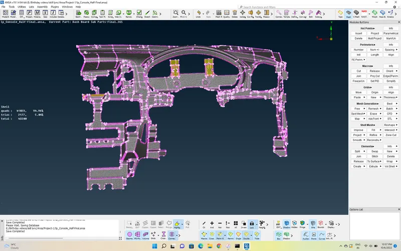
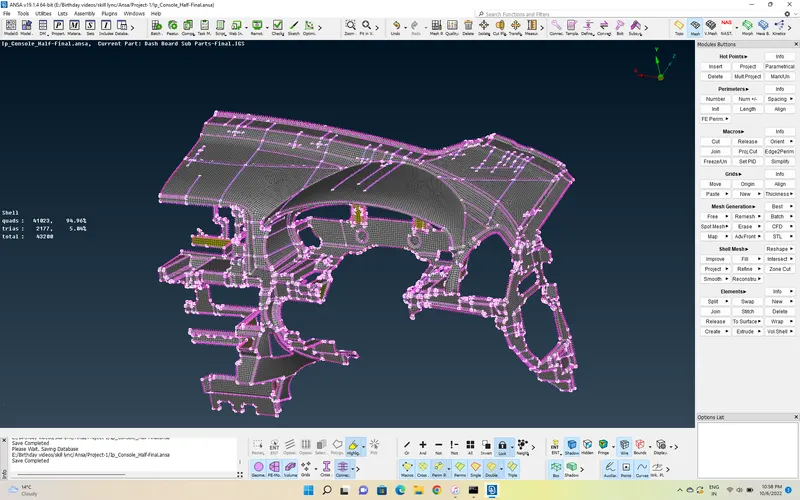
Meshed Model:
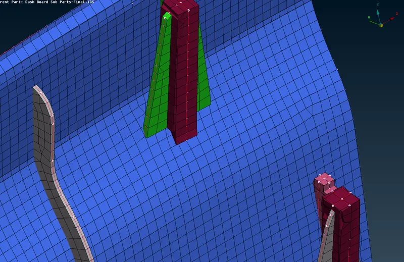
- Now, we have to apply the " Draw shell as solid " command to the meshed model to know, whether the thickness is applied accordingly or not.
Click on F11 >> Goto Presentation Parameters >> Tick the " Draw shell as solid " command box.
Model with " Draw shell as solid " command:
Learning outcomes: -
- Knowing the ANSA GUI and its tips for Better visualization.
- To practice all the commands in TOPO and Mesh Module.
- To know, how to handle the errors in geomentry, both manually and automatically.
- Mid surface extraction of plastic components using different options and some tricks.
- How to obtain a good mesh flow by adjusting construction lines and some defeaturing with lower percentage of traingles.
- Managing the Element quality using different commands in Mesh module.
- Assigning different PID's to different features according to their thicknesses.
Conclusion:
- Proper extraction of Mid surface.
- Generated Good Mesh flow.
- Tria's near Holes and Free edges are eliminated.
Link to the file is attached below.
https://drive.google.com/drive/u/0/folders/1qJwVN14nUUT0c2ES1mKS1sOZRSqTum5N