Project 1 - 2D meshing on the instrumental Panel
Aim:
The aim is for the given component, check for the geometrical errors and mesh with the given element Quality criteria. After meshing the component the thickness has to be assigned.
|
S.No |
Quality Criteria |
Value |
|
1 |
Target/Average length |
4 |
|
2 |
Minimum Length |
2 |
|
3 |
Maximum Length |
6 |
|
4 |
Aspect |
3 |
|
5 |
Warpage |
15 |
|
6 |
Skewness |
45 |
|
7 |
Jacobian |
0.7 |
|
8 |
Minimum Quad Angle |
45 |
|
9 |
Maximum Quad Angle |
135 |
|
10 |
Minimum Tria Angle |
30 |
|
11 |
Maximum Tria Angle |
120 |
|
10 |
Tria Percentage |
15 |
Procedure:
Initially the geometry clean up and the mid surface extraction is done,
then,Imported the given stp file in the ANSA work page.
Checked for the orientation,The issues with orientation are cleared using the topo module-->faces-->topo.
The resolution of the CONS is improved using Auxiliaries--> fine from topo module or perimeters- >length from mesh module.
The model is then subjected to a geometry checkup to check any free edges between the models, duplicate surface, irrelevant CONS using the option tools--> checks-->geometry.
Some geometrical errors are cleared using the Auto fix option and some are manually done using options like release hot points, release cons, topo, faces cut, etc. from the Topo module.
The geometrical errors are fixed and measured the model for different thicknesses using the Utilities- >measure option.
Since the model is varying for thicknesses, using the options faces-->middle-->single, faces-->offset from topo module, the manual mid-surface extraction is done.
Also options like curves-->create, CONS-->project points-->new faces-->new cut, topo etc. for creating the mid-surface.
Geometry check-up is done and a property ID is created, so the mid-surface is organized.
The surfaces are split accordingly to attain good mesh flow and to avoid element failures using the topo module--> faces-->cut option.
To check whether the mid-surface is perfectly captured, the transparency is turned ON to the parent geometry while keeping the Shadow mode ON and draw mode to PID from the drawing styles.
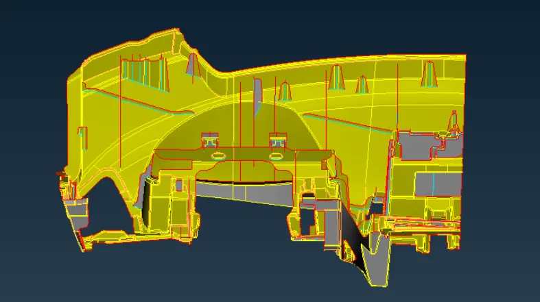
Then the mesh has been generated using the quality criteria given,
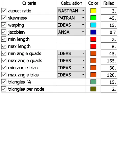
Then, the elements which fail for quality can be viewed by using the Draw mode toolbar --> hidden option and corrections are done for the elements which fail for quality.
Trias present at edges, fillet areas, pattern formation, opposite trias can be avoided using split, swap, reconstruct, edge2 perimeter, Num +/- options.
During meshing the opposite trias, back to back trias, trias present at the edges, rotational quads can be removed using shell mesh--> reconstruct option.
The smooth--shell mesh option is used to attain good mesh flow.
The perimeter elemental length of 4 mm is applied to the model using the mesh module --> perimeter--> length option,The split surfaces are meshed one by one using mesh module--> mesh generation--> Best and spot mesh option.
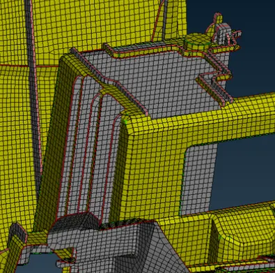
Then the thickness has been assigned and the model draw shell as solid.
Result :
Thus the given model has been completed successfully for the given criteria and has been uploaded.
Google drive link:
https://drive.google.com/file/d/1aY2ercjqnvfUonyhN6BvRBcHbUimhyOO/view?usp=sharing