Project 1 - 2D meshing on the instrumental Panel
Aim:
To check for the geometrical errors, take the Mid surface and mesh the Mid surface of IP console geometry with the given 2D element Quality criteria. After meshing the component the thickness has to be assigned.
Procedure:
Importing CAD model and geometrical error check:
- Import the CAD geometry in ANSA. The faces of the geometry are not stitched and not oriented properly.
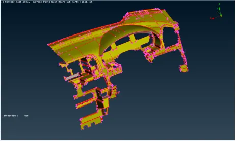
Figure 1 - Imported geometry of IP console model
-
Using Topo --> Faces --> Topo, the faces of the geometry are stitched together
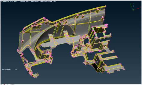
Figure 2 - Stitch the faces using Topo option
- Using Topo --> Orient --> Select/Visible, the faces of the geometry are oriented properly as shown below:
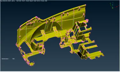
Figure 3 - Faces oriented properly
- Using Tools --> Checks --> Geometry, the geometry of the model are checked for errors in geometry
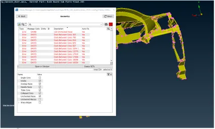
Figure 4 - Checking for errors in geometry
-
Select all the errors, right click and select “Fix” for fixing the errors automatically.
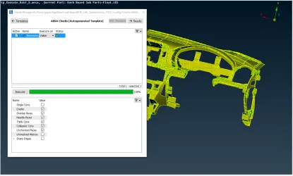
Figure 5 - Automatic Fixing of geometrical errors
- The given “Mesh parameters” and “Quality criteria” are entered and are saved as .mpar and .ansa_qual
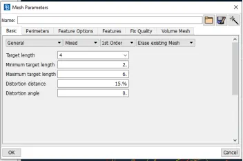
Figure 6 - Mesh parameters
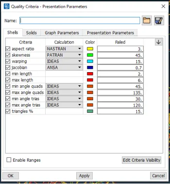
Figure 7 - Quality criteria - Perimeter Length is assigned to the component using Mesh --> Perimeters --> Length. Length is entered as 4.
Mid Surface generation:
The mid surface is generated for the model manually. The steps are explained below:
- Midsurface is generated using Topo --> Faces --> Offset option. By entering appropriate angle in the Feature Area option, multiple faces are selected and an appropriate offset distance is entered
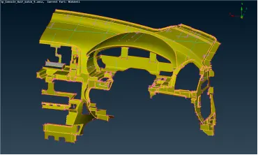
Figure 8 - Mid surface generation using Offset option
- Separate PSHELL properties are created based on the features in the geometry with different thickness
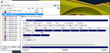
Figure 9 - Property creation
Mesh generation:
The initial defeaturing and meshing of the model was done using Batch mesh manager and is done as follows:
- In the model browser, a new part for the mid surface is created
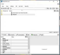
Figure 10 - New part creation in model browser
-
In the Batch mesh manager, a new Meshing scenario is created. Then, Right click on the meshing scenario --> Edit --> Contents. Then the mid surface part is assigned in the meshing scenario as shown below:
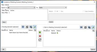
Figure 11 - Assign Contents in Meshing scenario
-
Then, the mesh parameters and quality criteria are checked and the option Run is clicked. Once complete, the status is shown as “Completed”
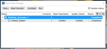
Figure 12 - Batch mesh manager after completion
- The completed mid surface using batch mesh is shown below:
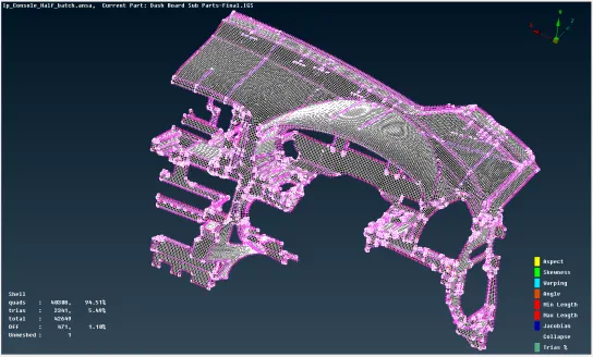
Figure 13 - Mesh generated using batch mesh manager
-
The mesh created using batch mesh still had many OFF elements and also unmeshed elements.
The elements that failed to generate from batch mesh and the elements that are found to be improved are corrected by using one of the below possibilities:
- Shell Mesh --> Reconstruct- to rearrange the mesh.
- Shell Mesh --> Smooth - to smoothen the mesh and arrange it equally
- Elements --> Swap - to rearrange the tria elements and hence better mesh flow
- Mesh --> Macros --> Cut or Topo --> Faces --> Cut - to create feature lines using left click and remove feature lines using right click
- Topo --> Faces --> New - to create new faces on the faces which were found improper in the geometry
The doghouses were captured as “cross pattern” in Mid surface. The radius of the doghouse was assigned as the thickness to this face.
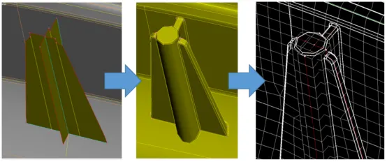
Figure 14 - Feature capturing of doghouses
Several elements in the mesh were not able to solve and these elements are kept in the model. The number of OFF elements in the model is 78.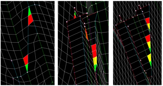
Figure 15 - OFF elements in the model
-
The final mesh of the IP console is shown below:
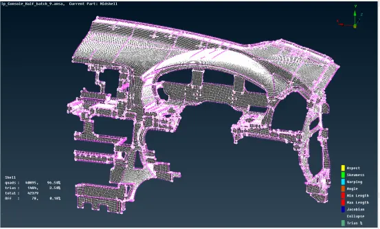
Figure 16 - Final mesh of IP Console
Learning Outcomes:
- Defeaturing and meshing using Batch mesh manager
- Extracting midsurface for solid doghouses and assigning thickness for it
- Creating mesh for a bigger complex model
Conclusion:
Thus, the given IP console model has been checked for the geometrical errors, Mid surface taken and the Mid surface is meshed with the given 2D element Quality criteria. After meshing the component the thickness has been assigned.
Drive Link of the model:
https://drive.google.com/file/d/1s_HTN-VWM4NHEW4GnOmkD9tsftwkSmiJ/view?usp=sharing