Project 1 - 2D meshing on the instrumental Panel
Project 1 - 2D meshing on the half-instrumental Panel
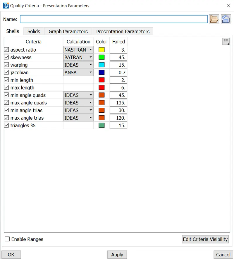
Aim: Checking for the geometrical errors, taking the mid surface, and meshing the given model with given element Quality criteria. (Refer to the table below for the Quality criteria)
Given sheet metal model: Half-instrumental Panel model
Given Quality criteria:
|
S.No |
Quality Criteria |
Value |
|
1 |
Average Length |
4 |
|
2 |
Minimum Length |
2 |
|
3 |
Maximum Length |
6 |
|
4 |
Aspect Ratio |
3 |
|
5 |
Warpage |
15 |
|
6 |
Skewness |
45 |
|
7 |
Jacobian |
0.7 |
|
8 |
Minimum Quad Angle |
45 |
|
9 |
Maximum Quad Angle |
135 |
|
10 |
Minimum Tria Angle |
30 |
|
11 |
Maximum Tria Angel |
120 |
|
12 |
Tria Percentage |
15 |
Procedure steps followed:
- Check for Geometrical errors and fix them.
- Extract mid surfaces manually for all different thicknesses using various mid surface techniques.
- Update the mesh quality criteria with the given Quality criteria and defeaturing the cons for minimum quality
- The meshing of the component mid surfaces
- Assigning different PID to different areas of the component in according to various thickness.
- Switching on Draw Shell as Solid in 'Quality Criteria' Dialog box
Procedure:
- Checking for Geometrical errors and fixing them for all components
After importing the given model into ANSA, checking for geometry cleanup is done from
Tools -> Checks -> Geometry -> Execute
Before Executing Geometry check After Executing the Geometry check
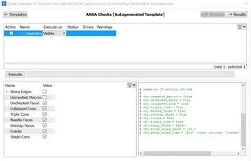
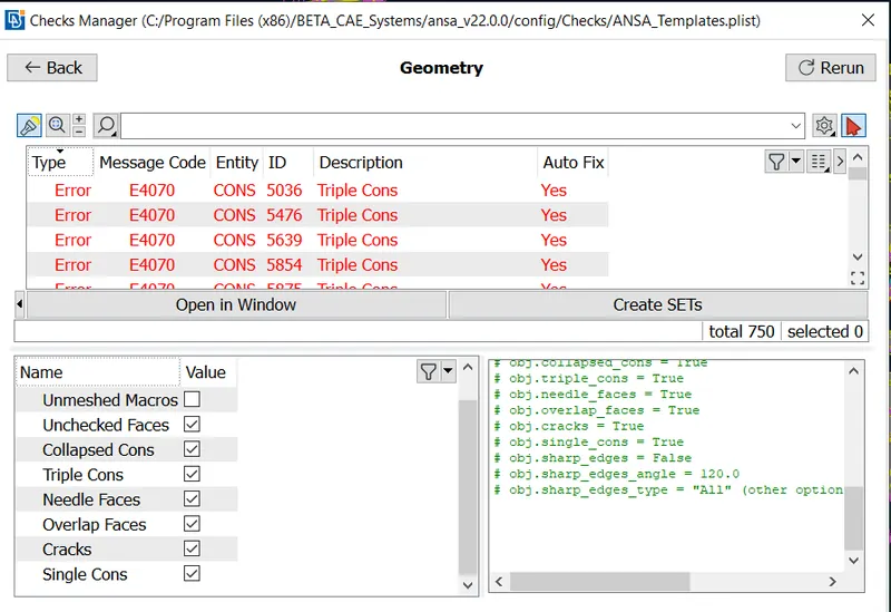
There errors are solved by Auto fixing them through clicking on the actions icon  in after check window -> Fix
Other than autofixing this model has incomplete surfaces due to the half model this is completed by
TOPO -> Faces -> New
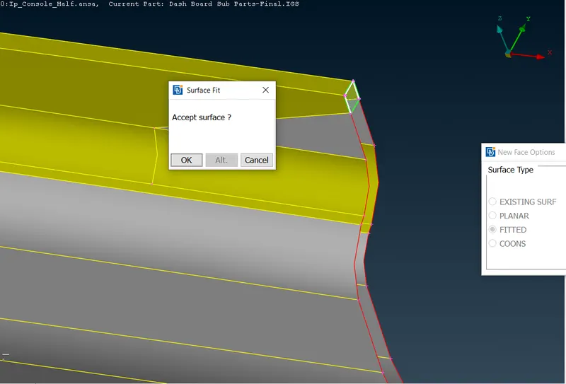
After Geometry cleanup
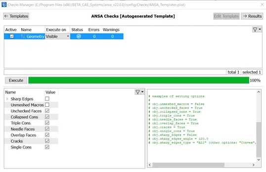
2. Extracting mid surfaces for all components after measuring the thickness of the components
After geometry cleaning is done,
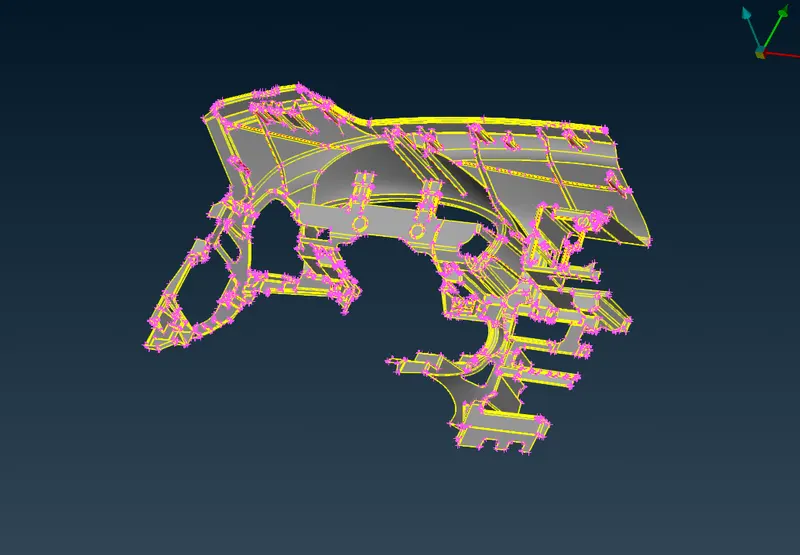
the thickness of different areas of the component is measured and stored for extracting the mid surface.
Since the given model is having varying thickness we use different techniques to extract mid surface.
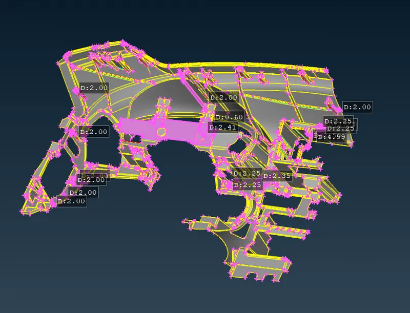
By dividing the whole part and storing it to different store locks we can extract mid surface easily.
The techniques used to extract mid surfaces include
(1) TOPO -> Curves -> Middle and TOPO -> Curves -> Cons2curve
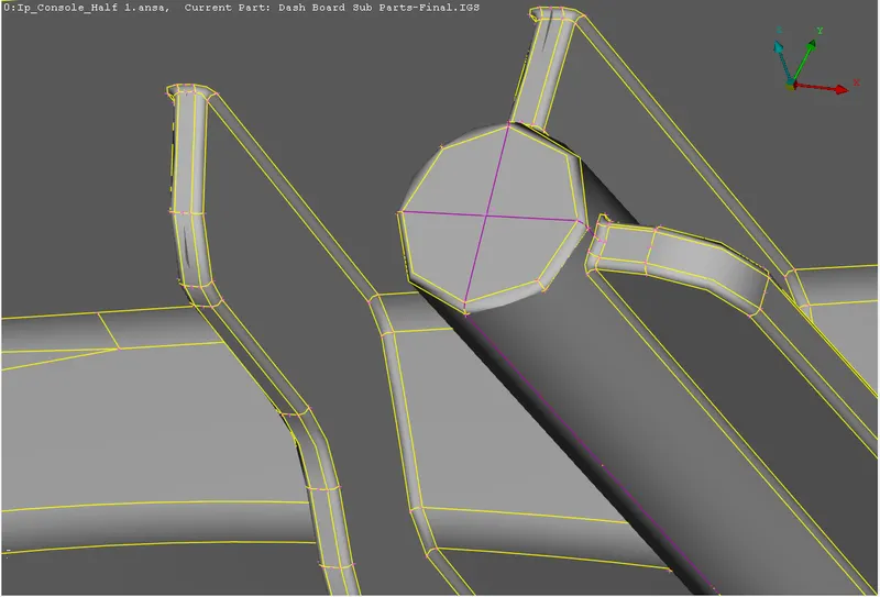
Here we use this by forming curves at middle of the part and using
TOPO -> Faces -> New
we form new surfaces which represents exact middle surfaces and extending it to next surface we get as shown below
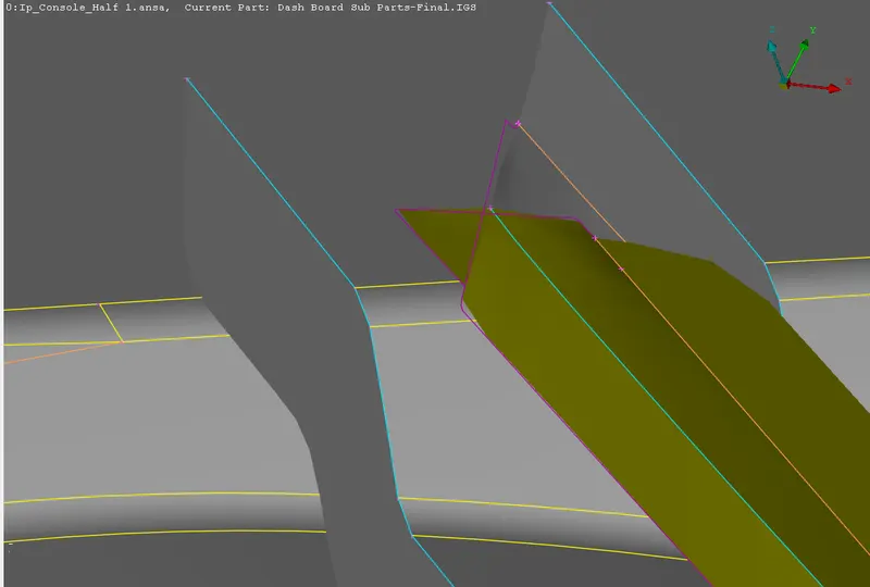
The cyan CON indicates the extended and intersected surfaces.
(2) Using TOPO -> Faces -> Offset -> Faces
We can extract mid sufaces which are having uniform thickness
By giving the offset value of 0.3 we form mid surface of outer surfaace and selecting using feature angle
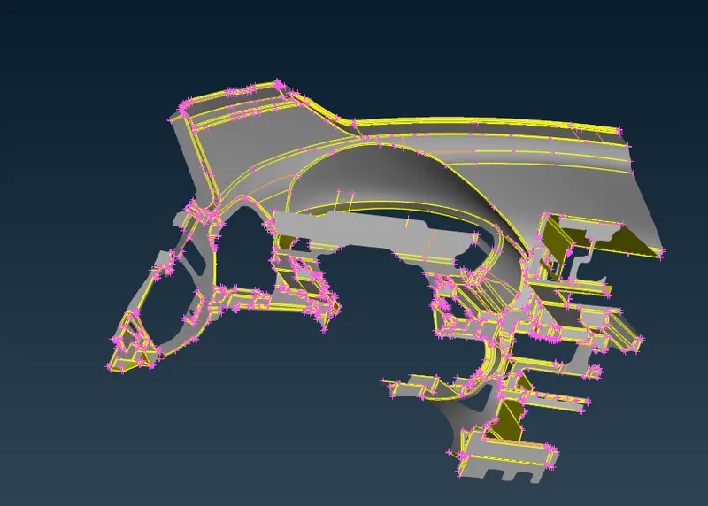
when extracting mid surfaces keeping the same PID makes it easier to mesh
For Dog house we follow the rib extending to the opposite surface of the dog house and giving the thickness of rib to the dog house cross.
The areas where features are only on oneside are taken in middle of that feature and the ens are projected onto the bottom surface.
The complete mid surfaces of the component is shown as below
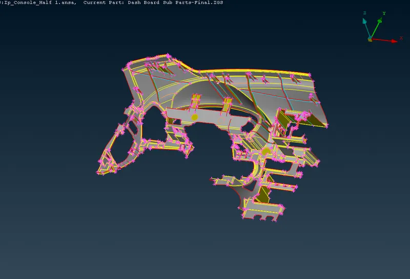
3. Update the mesh quality criteria with the given Quality criteria and defeaturing the cons for minimum quality
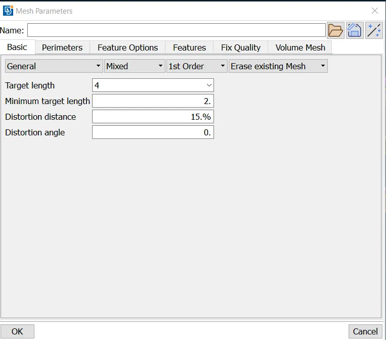
We update the given quality criteria and mesh parameters to further proceed to meshing
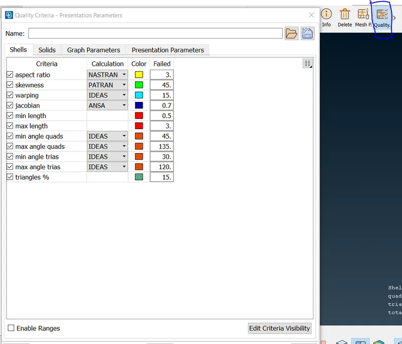
Quality Criteria
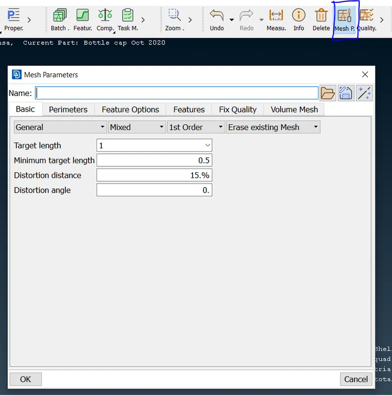
Mesh Parameters
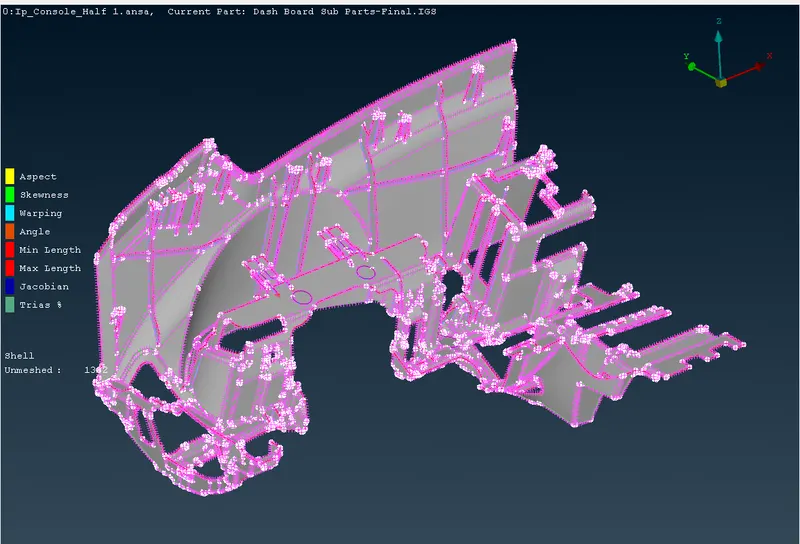
For the minimum quality defeaturing makes meshing time less
Defeatured midsurfaces is shown below
4. The meshing of the component mid surfaces
After updating the quality criteria we can proceed to mesh the component
Using
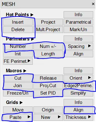
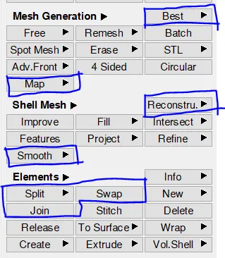
we mesh the component for within given quality criteria
and the other method after defeaturing batch meshing will be done in less time
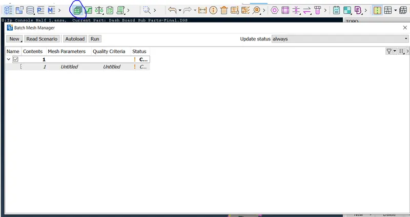
Editing by PID, selecting the mid surface, and running batch meshing, meshing is done
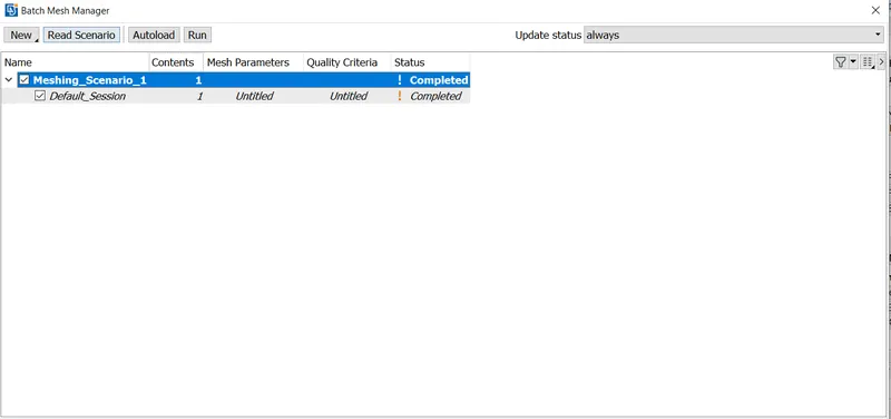
and the off elements are solved
The final meshed component is shown below affter solving off elements
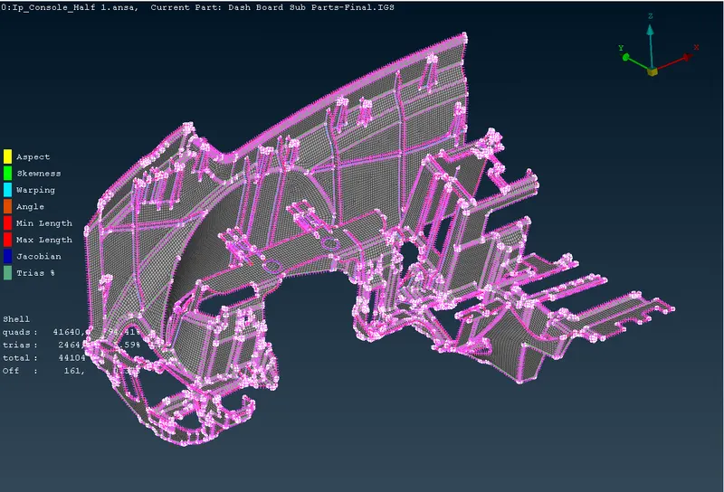
The off elements which are below minimum quality are between two triple cons and for proper feature capturing during meshing theses offf elements are given excepetion.
5. Assigning different PID to different areas of the component in according to various thickness.
After meshing is done, we can now assign PID to areas according to varying thickness
This can be done using MESH -> Macros -> Edge2Perimeter
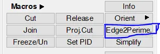
we can divide the mesh into different macros and using 'Set PID' and selecting the faces with same thickness
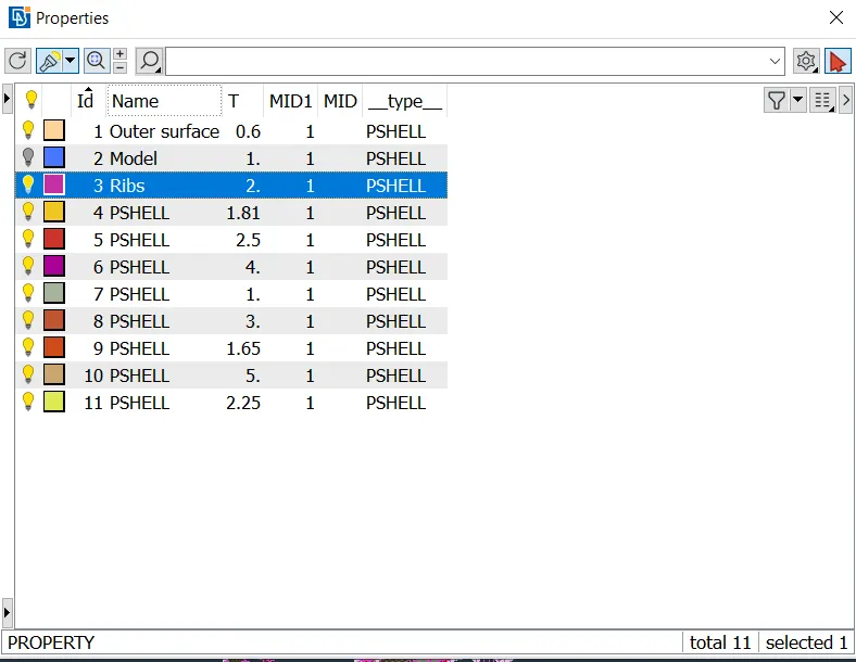
we can assign a differnt PID and the thickness of that area.
After assigning PID to different areas a different color is assigned to differentiate it.
After Assigning different PID according to their thickness
6. Switching on Draw Shell as Solid in 'Quality Criteria' Dialog box
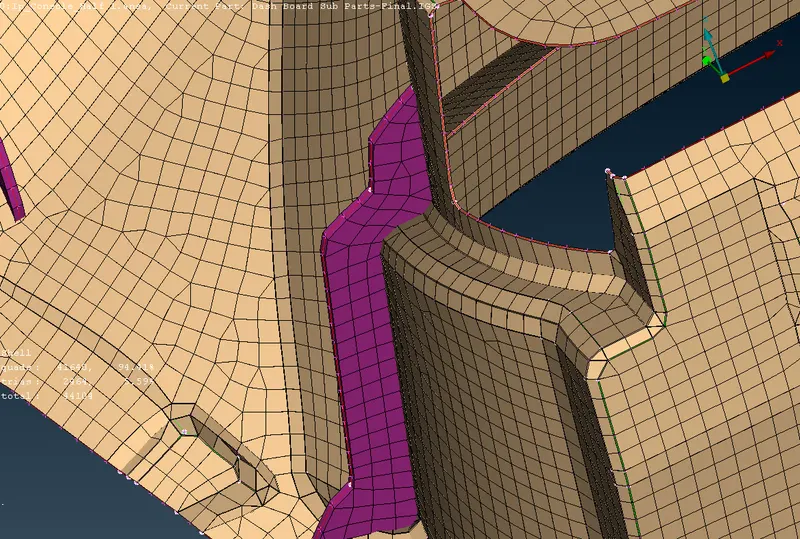
After assigning PID we switch on 'Shell as Solid' in "Quality Criteria -> Presentation Parameters" the component will be shown with the given thickness in mesh
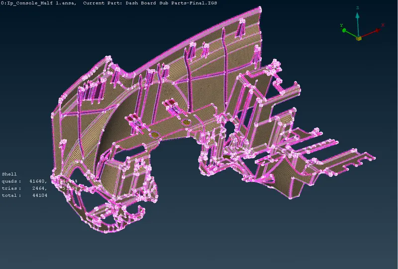
After swithching it on. we can see the final component with thickness switched on
Learning Outcomes:
- Cleaning of Geometry.
- Generating mid surfaces using feature selection, entity selection, Curves, Faces ->New, Extend and other different techniques.
- Meshing of component using different (Best, Map) Algorithms
- How to effectively use split, swap, join, paste commands in Mesh module for removing Trias and
rotating Quads. - Assigning PID using Edge2Perimeter
Conclusion:
Geometry cleanup and 2D meshing of given Bottle Cap model is done using ANSA v22.0