Project 1

Automotive Wiring Harness using CATIA V5
REPORT
Assignment-11
By Ravi Ahuja
Objective:
oute the Wiring harness on Given Engine and Prepare flatten view drawing in CATIA V5. Application of all Packaging rules, Industry best practices studied in this course shall be demonstrated in design. Apply Protection coverings as required.
Available connector 3D data can be used, or you can download the connectors from www.te.com
Prepare & Submit all necessary reports like clearance, Clipping/Clamping selection, Harness fixing requirements, Harness continuity, Assumptions if any along with CATIA 3D data.
Methodology: I started with downloading the step files of engine and electrical components which i was going to use inthe project. I converted them into part format and saved accodingly to prevent the mess.
Then I created a product file with name Context assembly and imported the engine part file for the reference.
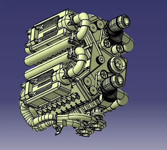
Then i created a product file in the context assembly with name geomectrical bundle and then started importing the connectors. Then I placed the connectors in their respective places but being in the geomectricla bundle assembly.
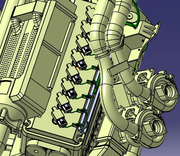
Then i started checking the electrical components before placing them if they are electrically defined.
An electrically defined connector or component has the publications on the feature tree.
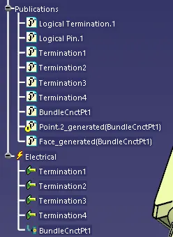
If these are not present then i would define the components one by one and then placed them to their respective positions.
I used 4 different type of connectors. After placing them I placed the wiring channel on each side of the engine to route the wires around the engine.
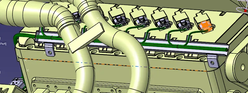
After placing the channel we can start the routing by multibranchable feature. in Electrcical harness assembly. Then I selected the geomectrial bundle feature to make the assembly alectrically defined.
Then I selected multi branchable feature  and then a new workbench appeared for multibranchable and a new part file was created for the same.
I started the routing from the left side from the 12 pin connector to the right most.
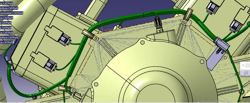
Then i continued to the channel and then routed in the channel by selecting the external curve feature.
Then I routed all the 8 connectors on each side and then finished the routing by connecting the remaining connectors too.
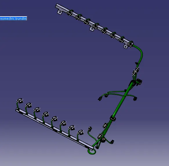
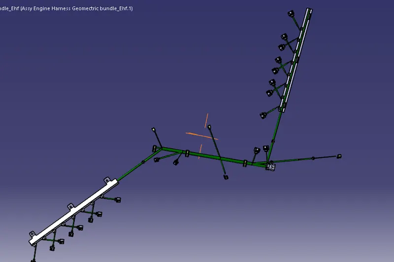
Then I have to use flattening for the same project. I switched to flattening workbench and created new product and named it flattening assembly.
Then I started adding flattening parameters by clicking it in the toolbar.
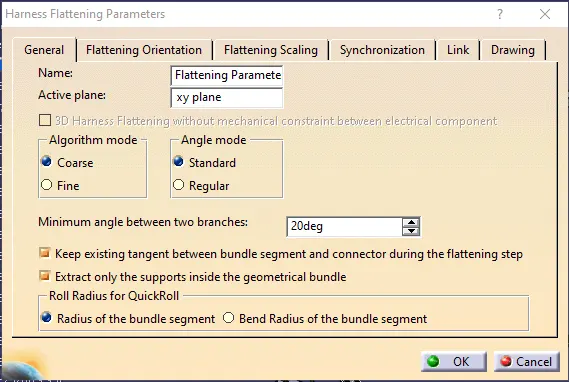
Then I selected flattening fr=eature on the toolbar and resilt appeared like this.
Then I saved all of this in a single folder and uploaded.