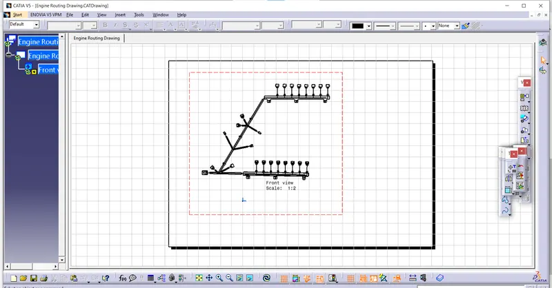
Project 1
Route the Wiring harness on Given Engine and Prepare flatten view drawing in CATIA V5
Harness Routing & packaging process
Wiring harness topology
Wiring harness Topology is strategy to Split the harness between different places to achieve the best manufacturability, Serviceability & cost effective design.
Harness Routing-
Harness routing shows the path of wiring harness into the vehicle. This is representation of the lay out of the wiring harness on the vehicle in geometrical way
Harness packaging-
Harness packaging involves the decisions of harness mountings (Clip & clamp) and Routing management( Use of Brackets, Channels, Guiding Devices)
It also deals with
Thermal management
Manufacturability
Clearance management
Aesthetic requirements etc….
Packaging rules-
1.Routing through small structural holes and openings shall be avoided, to minimize chaffing and handling of the wiring harness during installation.
2.Provide additional slack to the harness according to the surrounding and harness bending requirements. If harness is passing through the closures/ doors or tail gates, The envelope dimension during opening and closing of doors shall be considered to provide the slack.
Check the harness slack requirements with open and close conditions to avoid excess slack.
3.provide additional slack to the harness branch which connects to the loads and covered with enclosures.
4.Avoid routing over the bolts,Near to the joints, It may damage harness or may puncture the harness.
5.Keep the harness away from the panel mounting Bolts and screws.
6.Harness Should be kept away from Engine Lifting hooks
Process -
1.To Define the all the Connecter as a Electrical Component
2.To Define the P-Clamp As A Electrically
3.To Define Mounting Equipment As a Electrical Mounting Equipment
4.Next Preparation of harness assembly
5.Creating the wire harness geometrical bundle
6.Inserting harness components into geometrical bundle
7.Positioning your inserted electrical parts
8.Defining the wiring harness routing
9.Connecting & Disconnecting electrical components
10.Wiring Harness Flattening
1.To Define the all the Connecter as a Electrical Component
An Electrical Connector is an Electro mechanical device used to join Electrical termination and create an electric circuits. Electrical connectors consist of housing , Terminals ,wedge
Connectors are
Plastic molded housing with locking & Retention feature
Terminals are Metal Conductr with plating constructed in specific shape
Connector Definition In Catia V5
Download Connector 3D

Create Required Geometrical Parameters
Define Part as Connector
Define Bundle Connection (or) Entry Point
Define Connector Connection Point
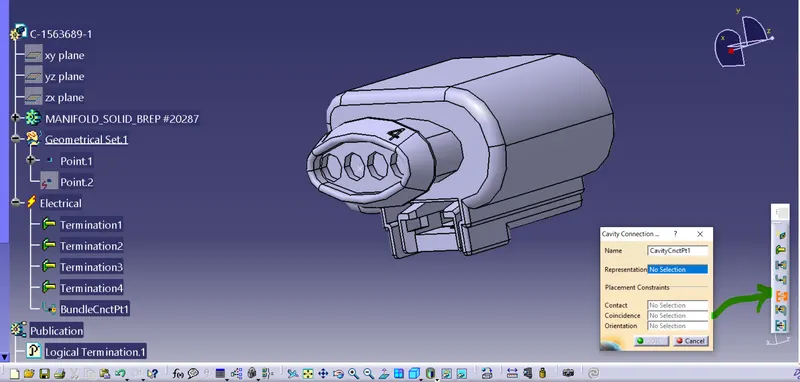
Define Cavity Connection point (optional) -
Download Connector 3D
Create Required Geometrical Parameters – Points & Axis (or) Co-ordinate System ( Working On Mechanical Part Design Work Bench)
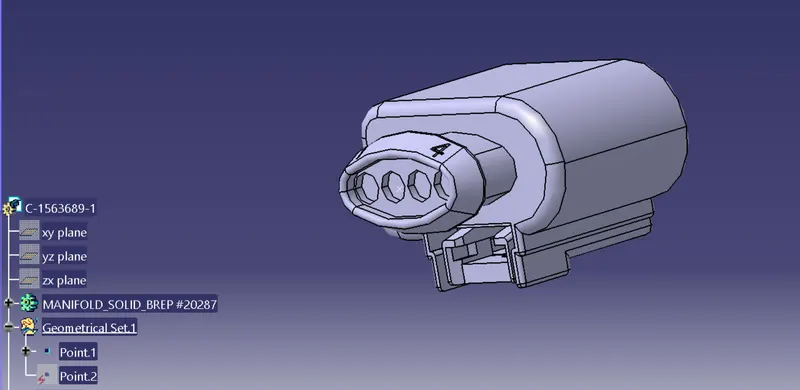
Now Switch to Mechanical Part Design Work Bench To Electrical Part Work Bench
Define Part as Connector - Select the Define Connector Icon
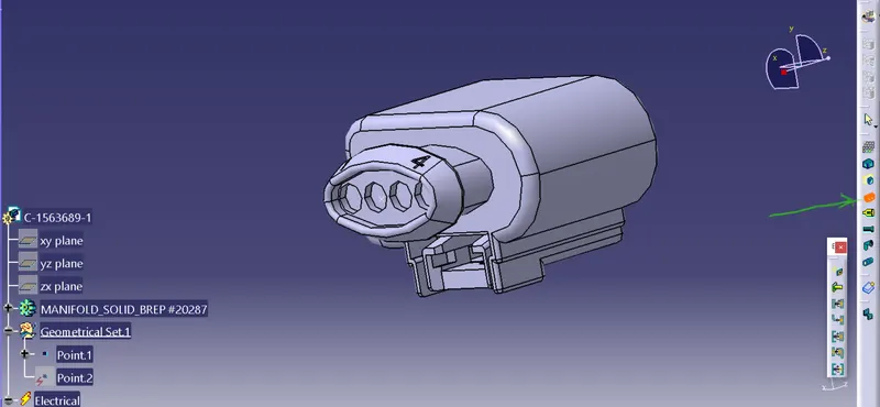
Define Bundle Connection (or) Entry Point – This points define where the harness bundle segments point will end when routed to the electrical connector.

Define Connector Connection Point – this point is used for the connection of one connector to another connector.
Here No need connector connection point,
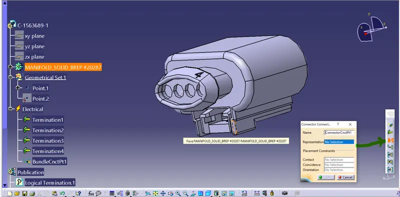
Define Cavity Connection point (optional) -This point is used to define the connection of a connector to a connector clip. This only applies to connectors which have the mounting feature for a connector clip.
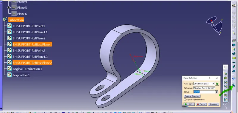
P-Clamp ;-
Get clamp 3Dpart

Define geometrical parameters
Define part as a support
Define Entry Point & Plane
Define Base & Exit Plane
Define part as a support
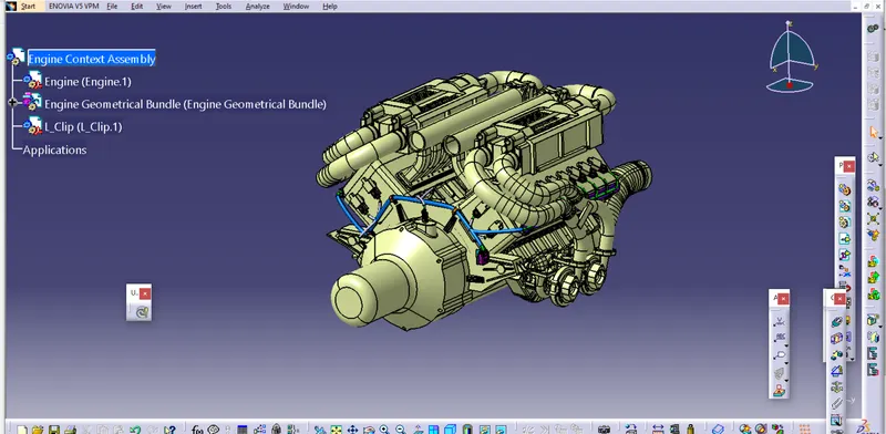
Wiring harness Product assembly Contains –
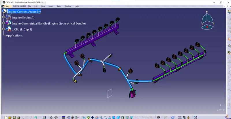
The Harness Context Assembly – This is the top level Product file that contains the harness Geometrical Bundle or Assembly and wire harness electrical bundle.
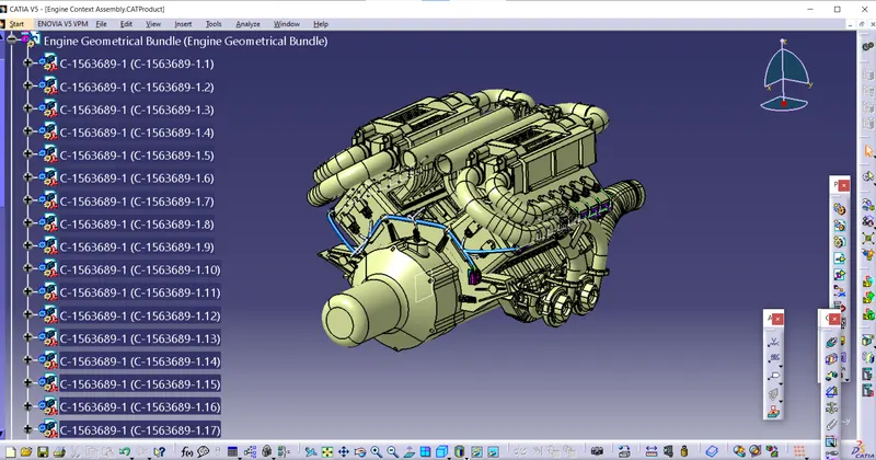
Geometrical Bundle – This sub level product file is the wire harness product that contains All the Harness components like connectors, P-lamp & Guiding Channel etc…
Positioning your inserted electrical parts
We need place the component at correct posision within the geometrical geometrical product file By using different Rotation/ Moving components like Translation , Manipulation, Snap, Smart Move etc
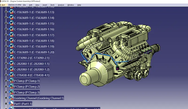
Switch to the Electrical Harness Assembly workbench
Harness geometrical bundle highlighted
Select the create multi Branch document icon
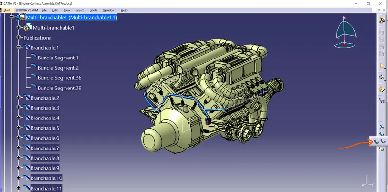
Defining the wiring harness routing
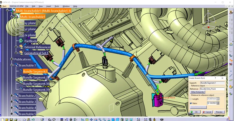
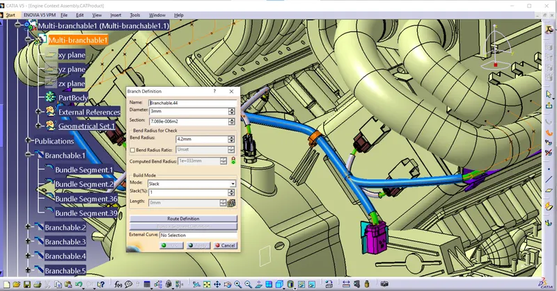
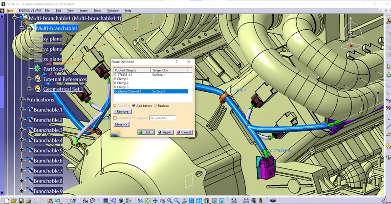
The branch definition box input all the required parameters
Ensure that the bend radius ratio is set to 1.4 or more than 1.5
Slect the route definition button, Now route definition box will appeare.
Selct the first electrical component were you start the harness route from
Here I am select the connector
Now slect the next electrical component what I want to route to , Again going the same process until the end.
Electrical Bundle – This Sub level product file contains all of the electrical Circuit.
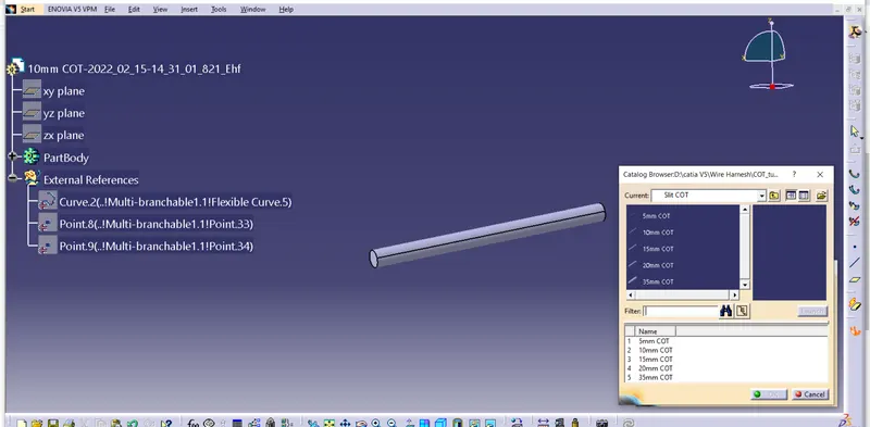
Cot Tubes
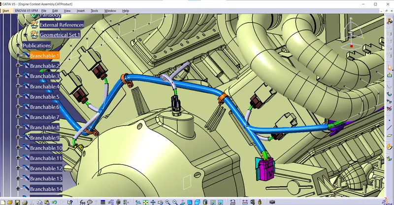
Final Routing
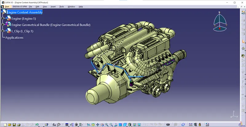
Connecting & Disconnecting electrical components
We need to check all the bundle connection are properly linked with the connector/ components or not
Edit – Search – Advanced tab – Electrical – Bundle Segment – fully connected for the attribute – false on the attribute box – ok – Search Icon
Wiring Harness Flattening
After checking all the bundle segments are linked we need to do the flattening
Switch to flattening work bench
Select the Harness flattening parameter from the Catia work bench
Select the All Tabs and use the setting for our requirement
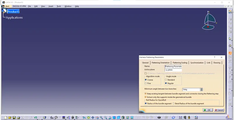
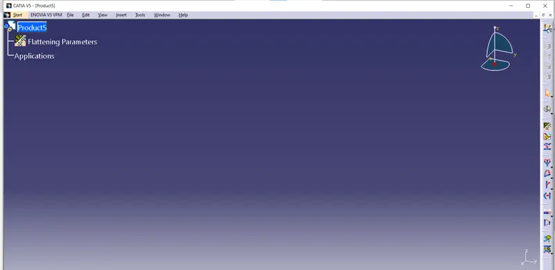
Now selct the Extract icon From catia work bench,Select the Geometrical Bundle from the harness you want to flatten
If we observe the Original Geometrical Bundle copied and Automatically been re named with the addition of EHF.
Select the Flatten Icon from the Catia Workbench
Select the geometrical bundle from the tree
In the flatten options box use the standard plane then its come to the flattening
3D Annotations –
It is used on the wiring harness to show connector functions and additional notes, using annotation tool bar.
Create a New Drawing File
Fit the Required view for the Drawing
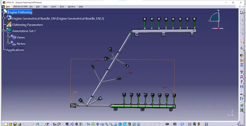
Now we need to fit for the Drawing purpose, if Any changes required using other commands like Rotate, Bend , Roll etc.. Modify the Diagram.