Project 1
Aim: To make mold blocks for the given component and add sliders and ejectors where ever necassary.
1. Core and Cavity Surface
To create the core and cavity surfaces, first the component is scaled to compensate for the shrinkage. Next, parting line is created and the surfaces needed to be shut-off are closed to make the core and cavity surface. To make the surfce that are used to cut the block, the necassary surfaces are extended and knited together with the core and cavity surface separatly. Thus, making 2 surfaces: core and cavity surface.
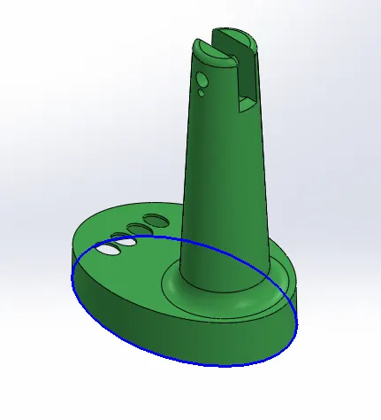
Parting Line (in blue)
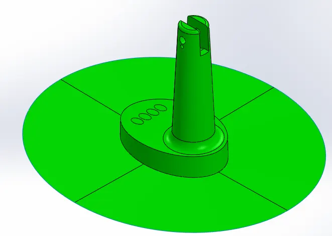
Cavity Surface
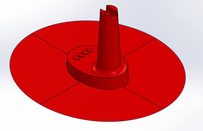
Core Surface
2. Core and Cavity Block
First, new part files need to be added to the assembly to make the core and cavity block. After adding the part files, sketch is created in the top plane with necassary clearance from the component. Extruding the sketch and cutting the block using cut with surface option the core and cavity block is created.
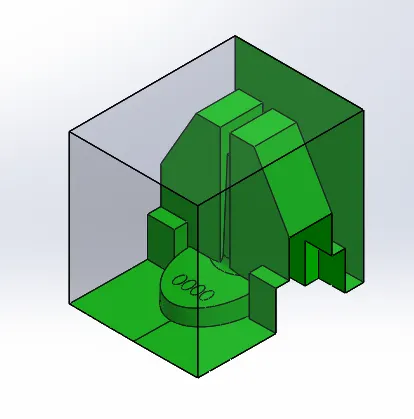
Cavity Block (After addition of sliders)
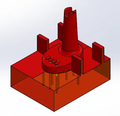
Core Block (After adding sliders and ejectors)
3. Ejector Pins
Ejector pins are required to remove the final product out of the cavity from the core side. The ejector pins are usually of 6mm dia and in critial cases 3mm dia ejectors can be used as well. Ejectors are usually placed near rib areas.
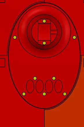
Ejector pins (in yellow)
4. Sliders
Components with undercuts nees sliders. For the creation for sliders teh cavity block is split as required and cut at a slant and collar is added to accomodate the washers and bolts. Once the sliders is made, necassary changes are done on the cavity and core block. The slider part is saved seperatly and imported under a new product.
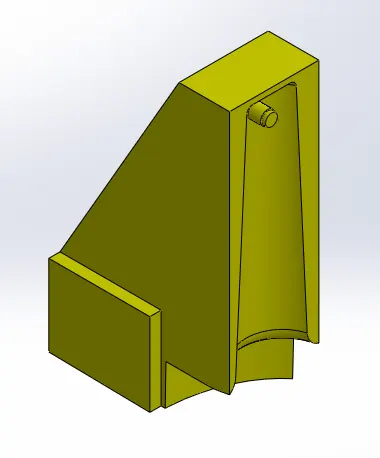
Slider 1
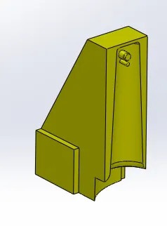
Slider 2
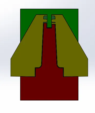
Cross-section of undercut.
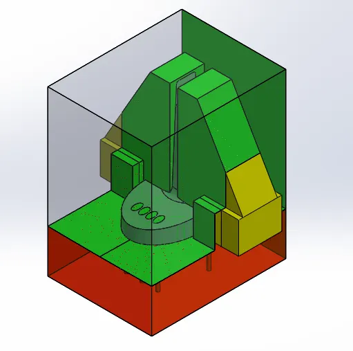
Assembly
Conclusion: Thus, the mold design for given component is completed with all sliders and ejectors added as necassary.