Project 1
1) Aim: To develop a Double-acting model in Simulink using Mechanical and Hydraulic Simscape blocks.
Construction and Working Principle:
a). A Physical Double-acting cylinder is created using the Solid block from the Simscape foundation library, and connected as shown below
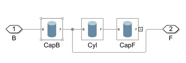
Cylinder assembly
The parameters of the Solid of the Cylinder i.e, Radius, Length, Density, and Frames are taken as shown below
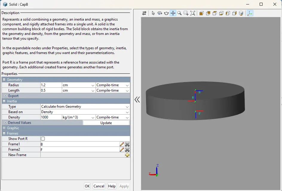
Parameters of the bottom cylinder cap
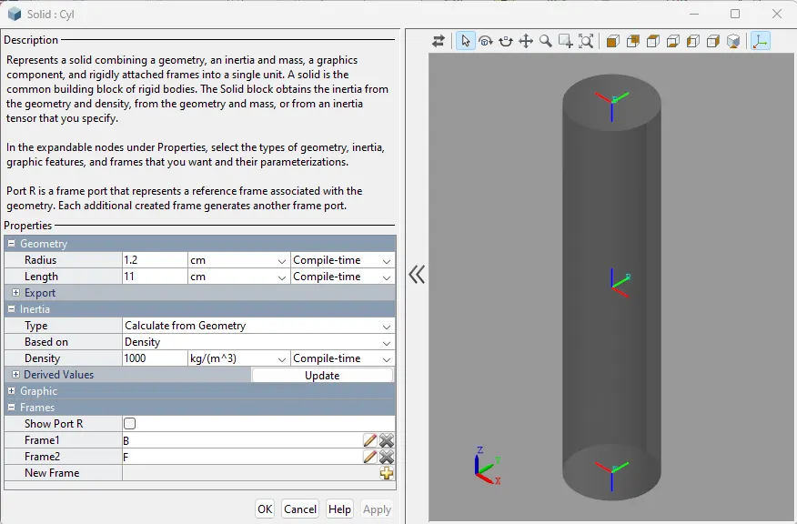
Parameters of the Piston cylinder
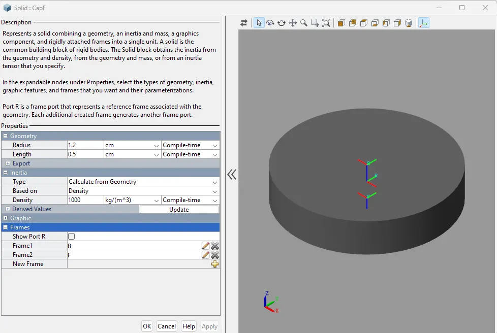
Parameters of the Top cylinder cap
The following is the connection of the Piston assembly,
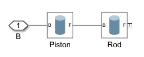 Piston assembly
The parameters of the Solid of the Piston i.e, Radius, Length, Density, and Frames are taken as shown below,
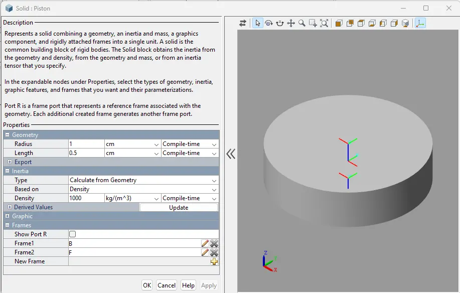
Parameters of the Piston
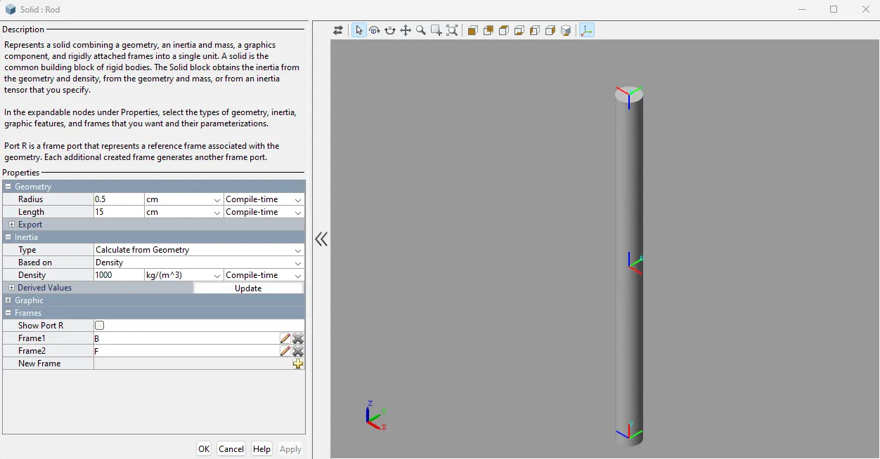
Parameters of the Piston rod
b). The Cylinder and Piston assembly are connected with the Prismatic joint block, giving the translation motion to the piston inside the cylinder.

Prismatic Joint
The Force input is provided by an external signal, and the velocity is selected for sensing output as shown in the below image,
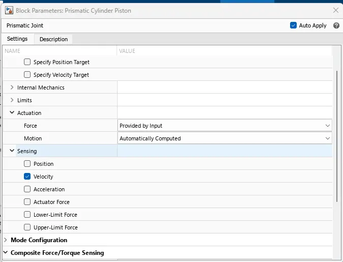
Parameters in Prismatic Joint block
The 'B' node of the Prismatic joint is connected to the 2nd connection of the Cylinder assembly, and the 'F' node of the Prismatic joint is connected to the 1st connection of the Piston assembly
c). The Piston cylinder assembly works by the Hydraulic system, to create the movement, we have to connect the "Translational mechanical interface block" between the Prismatic joint and the Hydraulic system,
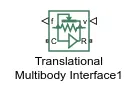
Translational multibody interface block
The 'f' node is connected to the input node of the Prismatic joint, the 'v' node is connected to the output node of the Prismatic joint, the 'C' node is connected to the 'C' node of the Hydraulic cylinder, and the 'R' node is connected to the 'R' node of the Hydraulic cylinder, which is connected next to this block
D). To make the Double acting cylinder work, it should interface with the Hydraulic cylinder, so Double acting hydraulic cylinder block is taken from the Simscape Hydraulic library, and connected to the Translational multibody interface block.
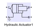
Double-acting hydraulic cylinder
The A and B ports are connected to the A and B ports of the Single-stage servo valve, we have to give the parameters of the Hydraulic cylinder as shown below,
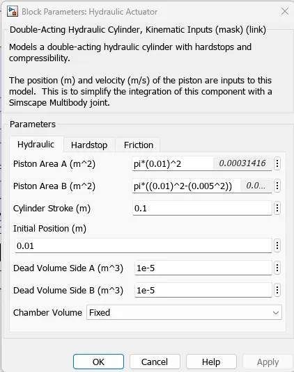
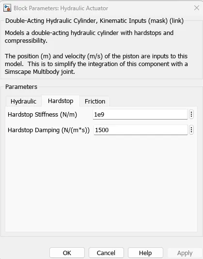
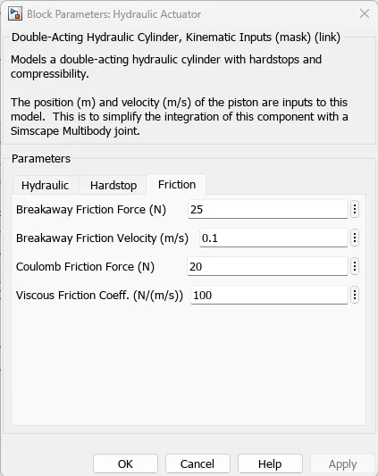
Parameters in Double-acting hydraulic cylinder block
E) Next to the Hydraulic cylinder, a Single-stage servo valve is connected, which passes the fluid to the A side and B side of the Hydraulic cylinder. When fluid passes through the A side, then the Piston will have the maximum position, and when fluid passes through the B side, then the Piston will have the minimum position.
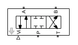
Single-stage servo valve
'Vi' port is connected to the Repeated sequence stair block, to take the signal, the 'P' port is connected to the Pressure source, the 'T' port is connected to the Reservoir
The parameters given to the Single-stage servo valve are as shown below,
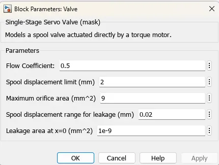
Parameters of Single-stage Servo Valve
F) To the Vi port, a Repeated sequence stair block is connected, which sends the signal to the Single-stage servo valve,

Repeated sequence stair block
The signal values are given to this as shown below,
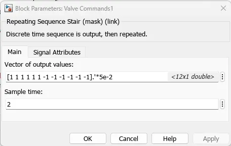
Parameters for Repeating Sequence Stair
if we give positive input from this block, then the Servo valve allows the fluid through port 'A', if the input is 0, then the fluid flow stops, and if the negative input is given, then the Servo valve will allow fluid through the Port 'B'.
G). To the 'P' port of the Servo valve, the Pressure source block is connected,

Pressure source block
This block is used to provide the parameter of the fluid pressure as shown below,
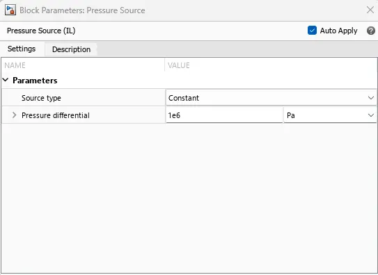
Parameters in Pressure Source
H). The Reservoir block is connected to the 'T' port of the Servo valve,
 Reservoir
This block serves as the Tank for Hydraulic fluid,
The parameters given to this block are as shown below,
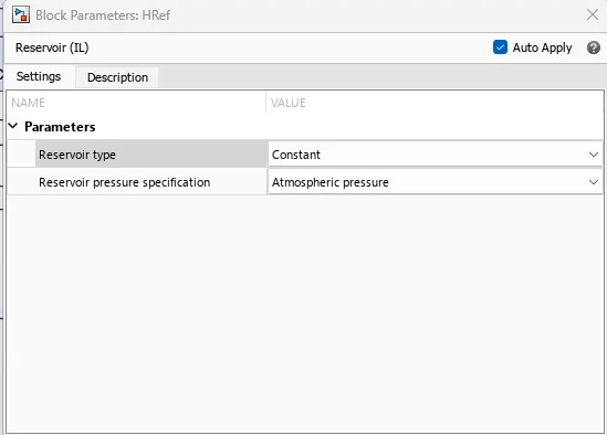
Parameters for Reservoir block
I). Then the Isothermal liquid properties Block is connected to the Tank, to give the properties of the Isothermal liquid,

Isothermal liquid properties block
The following are the parameters of this block,
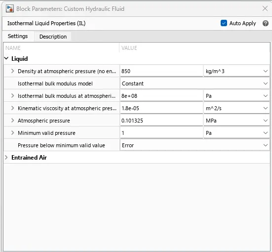
Parameters of the Isothermal liquid properties block
J). The common blocks we have to connect to the Multibody system are, the Mechanical configuration Block, World frame block, Solver configuration block
J.1. Mechanical configuration block is used to give the direction of gravity,

Mechanical configuration block
The Parameters given to this block are as shown below,
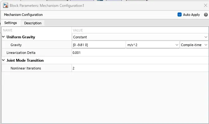
Parameters of the Mechanism configuration block
J.2. The World frame block is connected to give the reference coordinate system throughout the construction,

World frame block
J.3. The Solver configuration block is the common block used to every type of Simscape system,

Solver configuration block
These three blocks are connected each other,
K). The Mechanical transition reference block is also one of the important blocks, that we have to connect to the mechanical system,

Mechanical Transition reference block
The above blocks are connected according to the following Image,
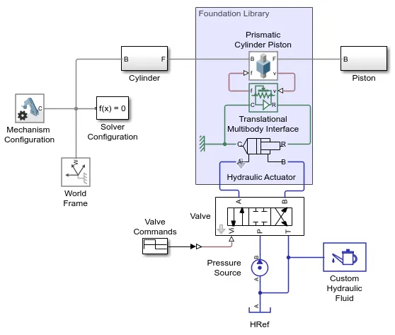
Construction of the Double-acting cylinder mechanism
Conclusion:
The above system is connected in the above way and runs, then the Piston moves Translation motion in the Cylinder, which called the Double-acting cylinder.
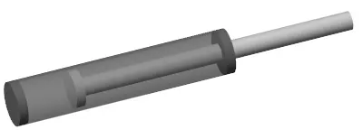
Double-acting cylinder assembly