Project 1
WIRING HARNESS ENGINE ASSEMBLY
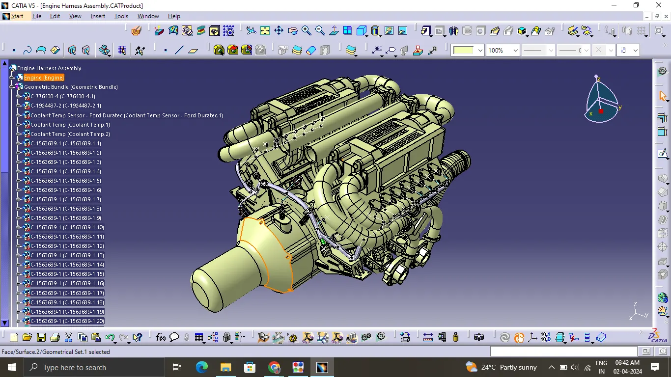
Route the Wiring harness on Given Engine and Prepare flattened view drawing in CATIA V5. Application of all Packaging rules, Industry best practices studied in this course shall be demonstrated in design. Apply Protection coverings as required.
Available connector 3D data can be used, or you can download the connectors from www.te.com
Prepare & Submit all necessary reports like clearance, Clipping/Clamping selection, Harness fixing requirements, Harness continuity, and Assumptions if any along with CATIA 3D data.
DESIGN FLOW OF EDS SYSTEM:
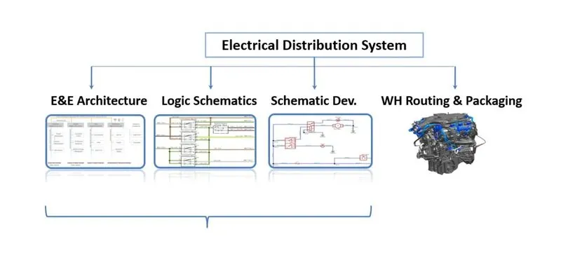
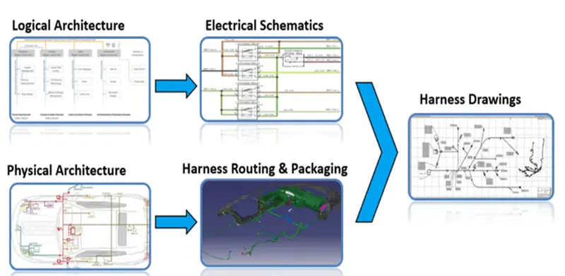
Logical Architecture, Electrical Schematics and Physical Architecture are designed by the electrical department whereas harness Routing and packaging is developed by the mechanical department. Upon integration of electrical and mechanical departments final harness drawing is designed.
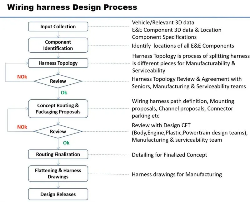
WIRING HARNESS COMPONENTS:
CONNECTORS:
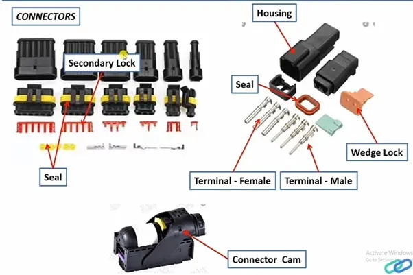
An electrical connector is an electro-mechanical device used to join Electrical termination and create an electric circuit. Electrical connectors consist of Housing, Terminal, Wedge Locks, Seals, Cavity, Mounting Cam etc., Connectors are plastic moulded housing with locking and retention features
-
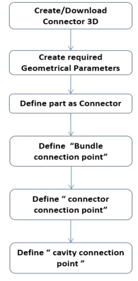
ELECTRICAL DEFINING PROCEDURE OF CONNECTOR
-
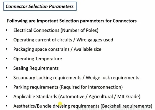
CONNECTOR SELECTION PARAMETERS
TERMINALS
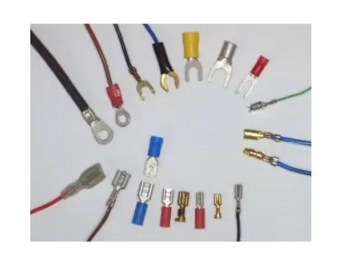
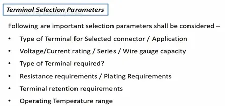
Terminals are defined as “A device designed to terminate a conductor that is to be affixed to a post, stud, chassis, another tongue, etc., to establish an electrical connection.” Terminals are metal (brass) conductors with plating (tin, silver, gold) constructed in specific shape to secure the joint from environmental conditions and with minimum electrical resistance.
WIRE
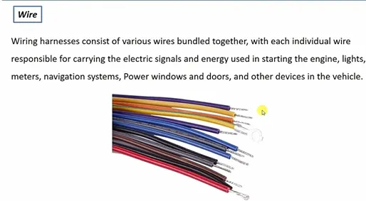
Wire Specifications:
-
Standard / Grade
-
Current carrying capacity
-
Resistance per metre
-
Insulation type/ Material
-
Colour of Wire
-
Temperature rating
Insulations: are adhesive/non-adhesive tapes and sleeves. They are made from PVC or cotton/polymer materials.

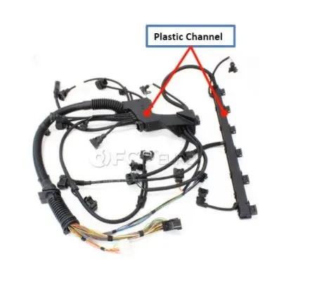
GUIDING CHANNEL
Guiding channels are Plastic moulded or Metal parts designed to guide harness bundle in a given geometric area to secure and Protect harness.
CLIPS
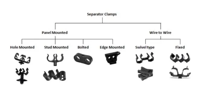
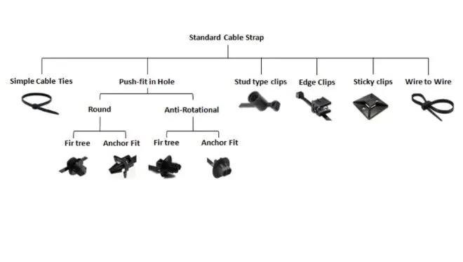
Simple Cable Ties are used in combination with Fir tree or Anchor Fit. Fir tree provides the multi locking while Anchor Fit can be removed with a push force. Stud type clips are simply pushed into the hole. Edge clips are costlier than any other clips and mounted on the panel edges. Sticky clamps stick to the flat surface of the body. Wire to wire is used to clamp one bundle to the other.
-
CLIP SELECTION PARAMETERS
GROMMETS
AIM:
To Route the Wiring harness on Given Engine and Prepare flatten view drawing in CATIA V5. Application of all Packaging rules, Industry best practices studied in this course shall be demonstrated in design. Apply Protection coverings as required.
How Does the Engine Wiring Harness Work:
There are many cables in the engine wiring harness that work to connect electricity to your vehicle parts. This vehicle part has many sensors, and they work to ensure that everything in your vehicle is in working order. Some of these major systems in your car are fuel and transmission. When you get a check engine light, you have the engine wiring harness to thank.
It works by using these cables and a fuse box. They wire the electricity produced by the engine to the various parts and sensors. It is created using high-temperature plastic or rubber because the engine heats up a lot. That could cause the engine wiring harness to melt over time. And while this is a rare occurrence, it does happen.
Think of this part of the vehicle like the brain. Without it, it wouldn’t be possible to get the information your vehicle needs. It’s always working overtime to relay the data your vehicle needs to function correctly. Whenever a sensor goes off, it’s because the engine wiring harness alerts the sensor of the problem.
The exciting thing is that as vehicles get more advanced, the engine wiring harness grows. Some say that new cars have over 100 pounds of wires, so imagine how many things could go wrong with that. In the past, there may not have been many issues. However, as things advance, there are more to go wrong.
Engine Wiring Harness protection:
Protecting the wires is crucial to the safety of the vehicle. Wires exposed to high temperatures, erosive chemicals and projectiles will be damaged leading to fires, brake failures and critical malfunctions. To prevent these issues, wires need to be bundled and covered.
install wiring insulation or heat shield sleeve material that can withstand direct contact with high-temperature surfaces and is flameproof. It needs to be a material built specifically for under-hood automotive applications and withstand constant temperatures up to 125°C, or 257°F.
There are many options for protecting the wires in a vehicle’s harness. Zip ties securely bundle wire together but offer little protection or insulation. Plastic conduits offer protection from rough surfaces, although they can add weight and are not as flexible as other options. Heat-shrink tubing provides protection from heat, moisture and chemicals. However, the application is time-consuming.
Tape is another option for bundling and protecting wires. Tapes are more flexible and cost-effective than other bundling options because they can be used for protective wrapping, bundling and sealing. With a wide variety of backings and adhesives, tape can offer sound dampening, thermal and electrical insulation and abrasion protection of the same quality as the other methods. Additionally, tapes are more flexible, lighter and easier to apply than tubing or plastic conduit.
DESIGN METHODOLOGY:
Step 1- download the engine CAD data and required connectors CAD data from the given source.
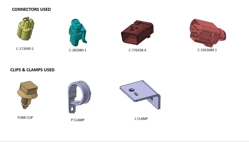
COMMPONENTS USED:
engine view :