Project 1
ANS 1. THE FOLLOWING IS A GENERAL PLAN FOR THE DESIGN OF A RESIDENTIAL BUILDING IN AN INDIAN CITY. THIS IS THE DESIGN BASIS REPORT FOR THE PROJECT. THE PROJECT CONSISTS OF A 6 STOREY BUILDING WITH THE GROUND FLOOR TO BE USED FOR PARKING PURPOSES. IT ALSO HAS A ROOF FOR COMMON USAGES.
THE DESIGN DATA IS AS FOLLOWS-
Live load : 4.0 kN/m2 at typical floor
: 1.5 kN/m2 on terrace
Floor finish : 1.0 kN/m2
Water proofing : 2.0 kN/m2
Terrace finish : 1.0 kN/m2
Location : Vadodara city
Wind load : As per IS: 875-Not designed for wind load, since earthquake loads exceed the wind loads.
Earthquake load : As per IS-1893 (Part 1) - 2002
Depth of foundation below ground : 2.5 m Type of soil : Type II, Medium as per IS:1893 Allowable bearing pressure : 200 kN/m2
Average thickness of footing : 0.9 m, assume isolated footings
Storey height : Typical floor: 5 m, GF: 3.4 m Floors : G.F. + 5 upper floors.
Ground beams : To be provided at 100 mm below G.L. Plinth level : 0.6 m Walls : 230 mm thick brick masonry walls only at periphery.
Material Properties
Concrete
All components unless specified in design: M25 grade all
Ec = 5 000 Fck^0.5 N/mm2 = 25 000 N/mm2 = 25 000 MN/m2 .
For central columns up to plinth, ground floor and first floor: M30 grade
Ec = 5 000 Fck N/mm2 = 27 386 N/mm2 = 27 386 MN/m2 .
Steel HYSD reinforcement of grade Fe 415 confirming to IS: 1786 is used throughout
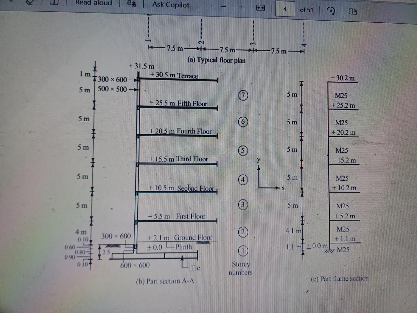
PORTION OF BUILDING STOREY NUMBER
Foundation top – Ground floor 1
Ground beams – First floor 2
First Floor – Second floor 3
Second floor – Third floor 4
Third floor – Fourth floor 5
Fourth floor – Fifth floor 6
Fifth floor - Terrace 7
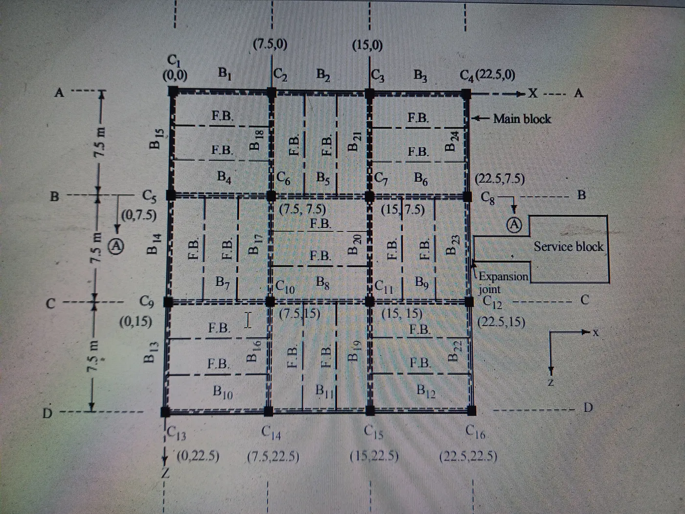
THIS IS THE GENERAL LAYOUT OF THE BUIDING-
COLUMN NUMBER-
In the general plan of Figure 1, the columns from C1 to C16 are numbered in a convenient way from left to right and from upper to the lower part of the plan. Column C5 is known as column C5 from top of the footing to the terrace level. However, to differentiate the column lengths in different stories, the column lengths are known as 105, 205, 305, 405, 505, 605 and 705 [Refer to Figure 2(b)]. The first digit indicates the storey number while the last two digits indicate column number. Thus, column length 605 means column length in sixth storey for column numbered C5. The columns may also be specified by using grid lines.
FLOOR BEAMS (SECONDARY BEAMS)- The reactions of the floor beams are calculated manually, which act as point loads on the main beams. Thus, the floor beams are not considered as the part of the space frame modelling.
MAIN BEAMS NUMBER-Beams, which are passing through columns, are termed as main beams and these together with the columns form the space frame.
GRAVITY LOAD CALCULATIONS-
UNIT LOAD CALCULATIONS-
Assumed sizes of beam and column sections are:
Columns: 500 x 500 at all typical floors
Area, A = 0.25 m2 , I = 0.005208 m4
Columns: 600 x 600 below ground level
Area, A = 0.36 m2 , I = 0.0108 m4
Main beams: 300 x 600 at all floors
Area, A = 0.18 m2 , I = 0.0054 m4
Ground beams: 300 x 600
Area, A = 0.18 m2 , I = 0.0054 m4
Secondary beams: 200 x 600
MEMBER SELF WEIGHTS-
Columns (500 x 500) 0.50 x 0.50 x 25 = 6.3 kN/m.
Columns (600 x 600) 0.60 x 0.60 x 25 = 9.0 kN/m.
Ground beam (300 x 600) 0.30 x 0.60 x 25 = 4.5 kN/m.
Secondary beams rib (200 x 500) 0.20 x 0.50 x 25 = 2.5 kN/m.
Main beams (300 x 600) 0.30 x 0.60 x 25 = 4.5 kN/m.
Slab (100 mm thick) 0.1 x 25 = 2.5 kN/m2.
Brick wall (230 mm thick) 0.23 x 19 (wall) +2 x 0.012 x 20 (plaster) = 4.9 kN/m2.
Floor wall (height 4.4 m) 4.4 x 4.9 = 21.6 kN/m.
Ground floor wall (height 3.5 m) 3.5 x 4.9 = 17.2 kN/m.
Ground floor wall (height 0.7 m) 0.7 x 4.9 = 3.5 kN/m.
Terrace parapet (height 1.0 m) 1.0 x 4.9 = 4.9 kN/m.
SLAB LOAD CALCULATIONS-
Component Terrace (DL + LL) Typical (DL + LL)
Self (100 mm thick) 2.5 + 0.0 2.5 + 0.0
Water proofing 2.0 + 0.0 0.0 + 0.0
Floor finish 1.0 + 0.0 1.0 + 0.0
Live load 0.0 + 1.5 0.0 + 4.0
Total 5.5 + 1.5 kN/m2 3.5 + 4.0 kN/m
BEAM AND FRAME LOAD CALCULATIONS-
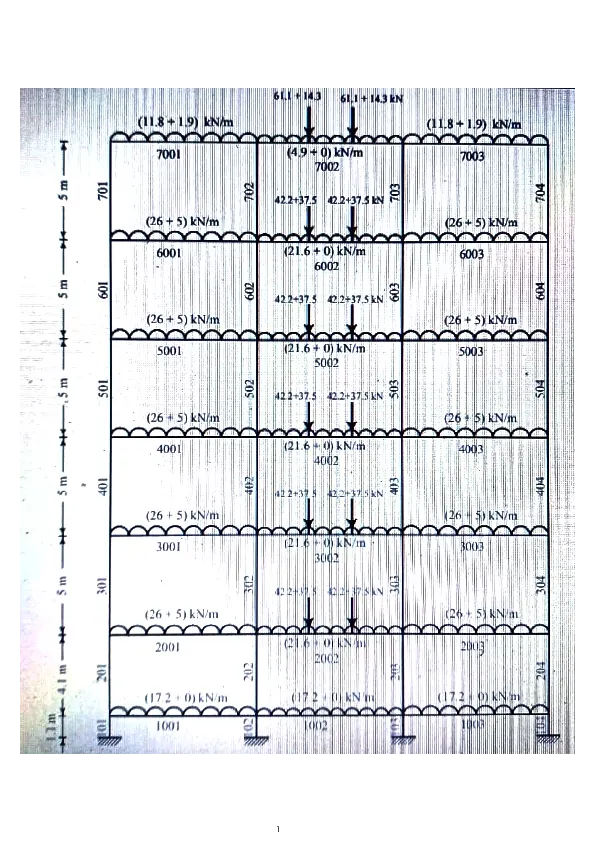
1. TERRACE LEVEL-
Floor beams:
From slab
2.5 x (5.5 + 1.5) = 13.8 + 3.8 kN/m
Self weight = 2.5 + 0 kN/m
Total = 16.3 + 3.8 kN/m
Reaction on main beam
0.5 x 7.5 x (16.3 + 3.8) = 61.1 + 14.3 kN.
Main beams B1–B2–B3 and B10–B11–B12
Component B1-B3 B2
From Slab
0.5 x 2.5 (5.5 +1.5) 6.9 + 1.9 0 + 0
Parapet 4.9 + 0 4.9 + 0
-----------------------------------------------------
Total 11.8 + 1.9 kN/m 4.9 + 0 kN/m
Two point loads on one-third span points for beams B2 and B11 of (61.1 + 14.3) kN from the secondary beams.
Main beams B4–B5–B6, B7–B8–B9, B16– B17– B18 and B19–B20–B21
From slab
0.5 x 2.5 x (5.5 + 1.5) = 6.9 + 1.9 kN/m
Total = 6.9 + 1.9 kN/m .
Two point loads on one-third span points for all the main beams (61.1 + 14.3) kN from the secondary beams.
Main beams B13–B14–B15 and B22–B23–B24.
Component B13 – B15 B22 – B24 B14 B23
From Slab
0.5 x 2.5 (5.5 +1.5) ---- 6.9 + 1.9
Parapet 4.9 + 0 4.9 + 0
----------------------------------------------------------------
Total 4.9 + 0 kN/m 11.8 + 1.9 kN/m
FLOOR LEVEL-
FLOOR BEAMS-
From slab
2.5 x (3.5 + 4.0) = 8.75 + 10 kN/m
Self weight = 2.5 + 0 kN/m
Total = 11.25 + 10 kN/m
Reaction on main beam 0.5 x 7.5 x (11.25 + 10.0) = 42.2 + 37.5 kN.
Main beams B1–B2–B3 and B10–B11–B12
Component B1 – B3 B2
From Slab
0.5 x 2.5 (3.5 + 4.0) 4.4 + 5.0 0 + 0
Wall 21.6 + 0 21.6 + 0
------------------------------------------------------
Total 26.0 + 5.0 kN/m 21.6 + 0 kN/m
Main beams B4–B5–B6, B7–B8–B9, B16– B17–B18 and B19–B20–B21.
From slab 0.5 x 2.5 (3.5 + 4.0) = 4.4 + 5.0 kN/m
Total = 4.4 + 5.0 kN/m
Two point loads on one-third span points for all the main beams (42.2 + 37.5) kN from the secondary beams.
Main beams B13–B14–B15 and B22–B23–B24.
Component B13 – B15 B22 – B24 B14 B23
From Slab
0.5 x 2.5 (3.5 + 4.0) ---- 4.4 + 5.0
Wall 21.6 + 0 21.6 + 0
-------------------------------------------------------------------------
Total 21.6 + 0 kN/m 26.0 + 5.0 kN/m
3. GROUND LEVEL-
Outer beams: B1-B2-B3; B10-B11-B12; B13- B14-B15 and B22-B23-B24.
Walls: 3.5 m high 17.2 + 0 kN/m
Inner beams: B4-B5-B6; B7-B8-B9; B16- B17-B18 and B19-B20-B21
Walls: 0.7 m high 3.5 + 0 kN/m.
SEISMIC WEIGHT CALCULATIONS-
The seismic weights are calculated in a manner similar to gravity loads. The weight of columns and walls in any storey shall be equally distributed to the floors above and below the storey. Following reduced live loads are used for analysis: Zero on terrace, and 50% on other floors [IS: 1893 (Part 1): 2002, Clause 7.4) .
(1) Storey 7 (Terrace):
DL+LL
From slab 22.5 x 22.5 (5.5+0) 2 784 + 0
Parapet 4 x 22.5 (4.9 + 0) 441 + 0
Walls 0.5 x 4 x 22.5 x (21.6 + 0) 972 + 0
Secondary beams 18 x 7.5 x (2.5 + 0) 338 + 0
Main beams 8 x 22.5 x (4.5 + 0) 810 + 0
Columns 0.5 x 5 x 16 x (6.3 + 0) 252 + 0
-------------------------------------------------------------------------
Total 5 597 + 0
= 5 597 kN
(2) Storey 6, 5, 4, 3:
DL+LL
From slab 22.5 x 22.5 x (3.5 + 0.5 x 4) 1 772 + 1 013
Walls 4 x 22.5 x (21.6 + 0) 1 944 + 0
Secondary beams 18 x 7.5 x (2.5 + 0) 338 + 0
Main beams 8 x 22.5 x (4.5 + 0) 810 + 0
Columns 16 x 5 x (6.3 + 0) 504+0
-----------------------------------------------------------------------
Total 5 368 +1 013
= 6 381 kN.
(3) Storey 2:
DL +LL.
From slab 22.5 x 22.5 x (3.5 + 0.5 x 4) 1 772 + 1 013
Walls 0.5 x 4 x 22.5 x (21.6 + 0) 972 + 0
Walls 0.5 x 4 x 22.5 x (17.2 + 0) 774 + 0
Secondary beams 18 x 7.5 x (2.5 + 0) 338 + 0
Main beams 8 x 22.5 x (4.5 + 0) 810 + 0
Columns 16 x 0.5 x (5 + 4.1) x (6.3 + 0) 459 + 0
----------------------------------------------------------------------
Total 5 125 +1 013
= 6 138 kN .
(4) Storey 1 (plinth):
DL+LL.
Walls 0.5 x 4 x 22.5 (17.2 + 0) 774 + 0
Walls 0.5 x 4 x 22.5 x (3.5 + 0) 158 + 0
Main beams 8 x 22.5 x (4.5 + 0) 810 + 0
Column 16 x 0.5 x 4.1 x (6.3 + 0) 206+0
16 x 0.5 x 1.1 x (9.0 + 0) 79 + 0
----------------------------------------------------------------------
Total 2 027 + 0
= 2 027 kN.
Seismic weight of the entire building = 5 597 + 4 x 6 381 + 6 138 + 2 027 = 39 286 kN.
DESIGN SEISMIC LOAD.
The infill walls in upper floors may contain large openings, although the solid walls are considered in load calculations. Therefore, fundamental time period T is obtained by using the following formula:
Ta = 0.075 h^0.75
[IS 1893 (Part 1):2002, Clause 7.6.1]
= 0.075 x (30.5)0.75 = 0.97 sec.
Zone factor, Z = 0.16 for Zone III IS: 1893 (Part 1):2002, Table 2
Importance factor, I = 1.5 (public building)
Medium soil site and 5% damping
Sa/g=1.36/097 = 1.402.
Storey Wi (kN) hi (m) Wihi^2 x10^-3 Qi=Wihi^2/SUM. Wihi^2*VB (kN) Vi (kN)
7 5 597 30.2 5 105 480 480
6 6 381 25.2 4 052 380 860
5 6 381 20.2 2 604 244 1 104
4 6 381 15.2 1 474 138 1 242
3 6 381 10.2 664 62 1 304
2 6 138 5.2 166 16 1 320
1 2 027 1.1 3 0 1 320
--------------------------------------------------------------------------------------------------------
Total 14 068 1 320.
Ah= Z/2*I/R*sa/g.
=0.16/2*1.5/5*1.402
= 0.0336.
Vb= Ah *W.
= 0.0336*39 286.
= 1320 KN.
STOREY DRIFT-
As per Clause no. 7.11.1 of IS 1893 (Part 1): 2002, the storey drift in any storey due to specified design lateral force with partial load factor of 1.0, shall not exceed 0.004 times the storey height. From the frame analysis the displacements of the mass centres of various floors are obtained and are shown in Table 4 along with storey drift. Since the building configuration is same in both the directions, the displacement values are same in either direction.
STOREY DRIFT CALCULATIONS.
Storey Displacement (mm) Storey drift (mm)
7 (Fifth floor) 79.43 7.23
6 (Fourth floor) 72.20 12.19
5 (Third floor) 60.01 15.68
4 (Second floor) 44.33 17.58
3 (First floor) 26.75 17.26
2 (Ground floor) 9.49 9.08
1 (Below plinth) 0.41 0.41
0 (Footing top) 0 0
STABILITY INDICES-
It is necessary to check the stability indices as per Annex E of IS 456:2000 for all storeys to classify the columns in a given storey as non-sway or sway columns.
Qsi= sum. Pu*delta/Hu*hs.
Hu = total lateral force acting within the storey.
hs = height of the storey.
delta = elastically computed first order lateral deflection.
Pu = SUM OF AXIAL LOAD ON EACH FLOOR.
Storey weight Wi Axial load Uu Lateral load Hs Qsi Classification
7 5 597 5 597 7.23 480 5 000 0.0169 No-sway
6 6 381 11 978 12.19 860 5 000 0.0340 No-sway
5 6 381 18 359 15.68 1 104 5 000 0.0521 Sway
4 6 381 24 740 17.58 1 242 5 000 0.0700 Sway
3 6 381 31 121 17.26 1 304 5 000 0.0824 Sway
2 6 138 37 259 9.08 1 320 4 100 0.0625 Sway
1 2 027 39 286 0.41 1 320 1 100 0.0111 No-sway
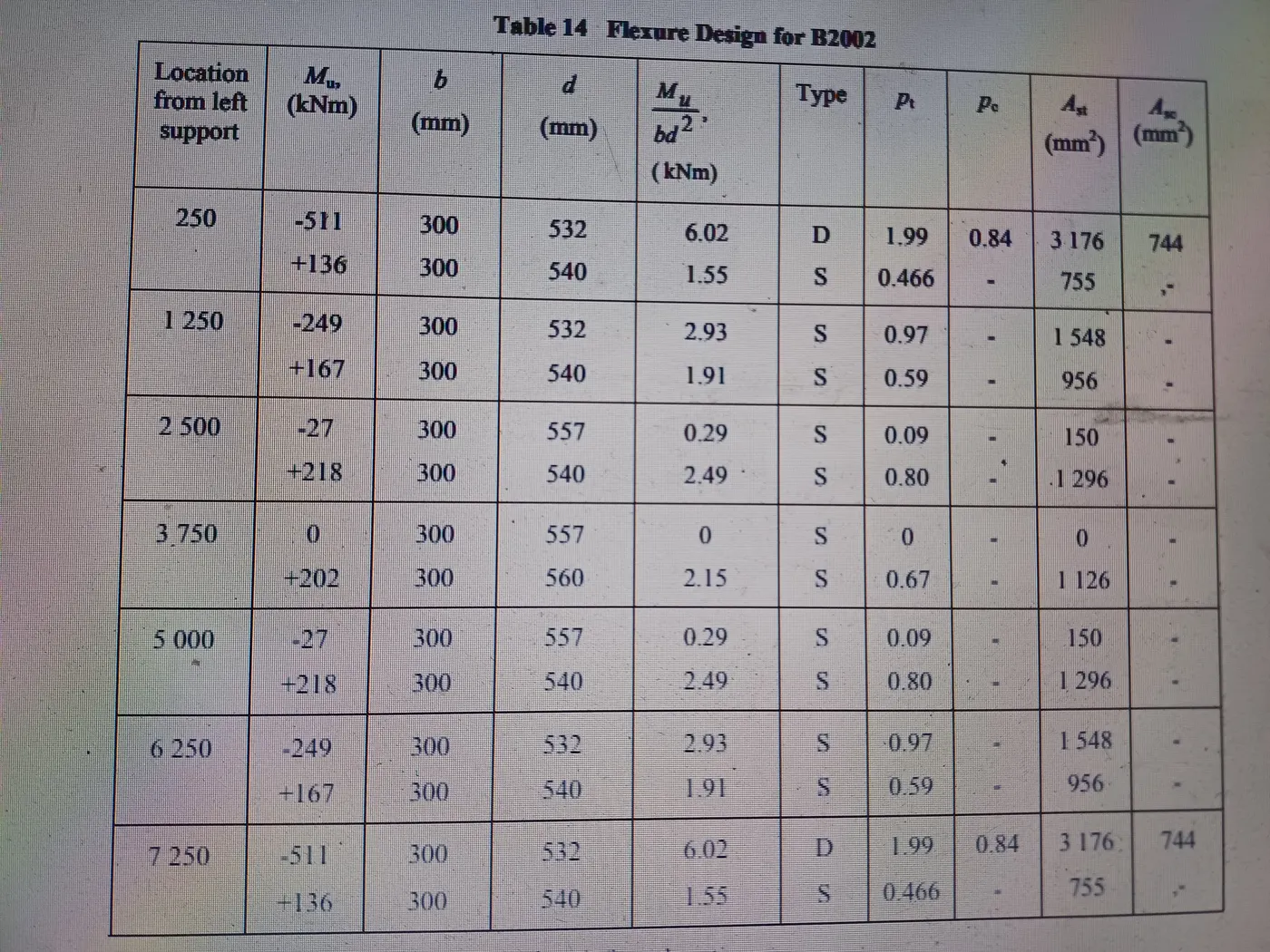
design of selected beams-
The flexural members shall fulfil the following general requirements.
(IS 13920; Clause 6.1.2)
b/D ≥ 0.3 Here b/D=0.5
HENCE IT IS OK.
b>=200mm.
WE HAVE b =300mm, HENCE OK.
D<=Lc/4.
Lc= 7500-500= 7000mm.
D = 600mm<7000/4 mm.
HENCE OK.
DESIGN OF FOOTING-
Since there is no limit state method for soil design, the characteristic loads will be considered for soil design. These loads are taken from the computer output of the example building. Assume thickness of the footing pad D = 900 mm.
(a) Size of footing:
Case 1: Combination 1, i.e., (DL + LL)
P = (2291 + 608) = 2899 kN Hx = 12 kN, Hz = 16 kN
Mx = 12 kNm, Mz = 6 kNm.
At the base of the footing P = 2899 kN
P’ = 2899 + 435 (self-weight) = 3334 kN,
assuming self-weight of footing to be 15% of the column axial loads (DL + LL).
Mx1 = Mx + Hy×D = 12 + 16 × 0.9 = 26.4 kNm
Mz1 = Mz +Hy×D = 6 + 12 × 0.9 = 18.8 kNm.
For the square column, the square footing shall be adopted.
Consider 4.2 m × 4.2 m size.
A = 4.2 × 4.2 = 17.64 m2
Z = 6 1 ×4.2 ×4.22 = 12.348 m3 .
P/A= 3344/17.64= 189 kN/m2.
Mx/Zx=26.4/12.348 = 2.14 kN/m2 .
Mz/Zz= 18.8/12.348= 1.52 kN/m2.
Maximum soil pressure = 189 + 2.14 + 1.52 = 192.66 kN/m2 < 200 kN/m2.
Minimum soil pressure = 189 – 2.14 – 1.52 = 185.34 kN/m2 > 0 kN/m2 .
CASE 2-
Permissible soil pressure is increased by 25%. i.e., allowable bearing pressure = 200 ×1.25 = 250 kN/m2 .
P = (2291 - 44) = 2247 kN
Hx = 92 kN, Hz = 13 kN Mx = 3 kNm, Mz = 216 kNm.
At the base of the footing
P = 2247 kN
P’ = 2247 + 435 (self-weight) = 2682 kN.
Mx1 = Mx + Hy×D = 3 + 13 × 0.9 = 14.7 kNm
Mz1 = Mz +Hy×D = 216 + 92 × 0.9 = 298.8 kNm.
P/A= 2682/17.64= 152.04 KN/m2.
Mx/Zx= 14.7/12.348= 1.19KN/m2.
Mx/Zx= 298.8/12.348= 24.20 KN/m2.
Maximum soil pressure = 152.04 + 1.19 + 24.2 = 177.43 kN/m2 < 250 kN/m2 .
Minimum soil pressure = 152.04 - 1.19 – 24.2 = 126.65 kN/m2 > 0 kN/m2 .
In fact all combinations may be checked for maximum and minimum pressures and design the footing for the worst combination.
Design the footing for combination 1, i.e., DL + LL.
P/A= 2899/17.64= 164.34KN/M2.
Factored upward pressures for design of the footing with biaxial moment are as follows.
For Mx pup = 164.34 + 2.14 = 166.48 kN/m2 pu,up = 1.5 ×166.48 = 249.72 kN/m2
For Mz pup = 164.34 + 1.52 = 165.86 kN/m2 pu,up = 1.5 ×165.86 = 248.8 kN/m2
Since there is no much difference in the values, the footing shall be designed for Mz for an upward pressure of 250 kN/m2 on one edge and 167 kn/m2 on the opposite edge.
(b) Size of pedestal: A pedestal of size 800 mm × 800 mm is used.
For a pedestal A = 800 ×800 = 640000 mm2
Z = 1/6*800*800*800.
= 85333333mm3.
FOR CASE 1.
q= 5.06N/m2.
FOR CASE 2.
q= 7.18N/m2.
Since 33.33 % increase in stresses is permitted due to the presence of EQ loads, equivalent stress due to DL + LL is
7.18 /1.33 =5.4 N/mm .
(2) From (1) and (2) consider q0 = 5.4 N/mm2 .
For the pedestal,
This gives 0 tanα ≥ 4.762 , i.e., α ≥ 78.14 Projection of the pedestal = 150 mm Depth of pedestal = 150 ×4.762 = 714.3 mm. Provide 800 mm deep pedestal.
MOMENT STEEL-
Net cantilever on x-x or z-z
= 0.5(4.2-0.8) = 1.7 m.
Muz = 1449 kNm
For the pad footing, width b = 4200 mm For M20 grade concrete, Qbal = 2.76. Balanced depth required.
Try a depth of 900 mm overall. Larger depth may be required for shear design.
Assume 16 mm diameter bars.
dx = 900 – 50 – 8 = 842 mm dz = 842 – 16 = 826 mm.
Average depth = 0.5(842+826) = 834 mm.
Design for z direction. = Mzz/ bd^2= 0.506.
pt = 0.145, from table 2, SP :16
Ast= 5841mm2.
Astmin= 4536 mm2
 Provide 28 no. 16 mm diameter bars. Ast = 5628 mm2 . 3 826 mm...... .... (o.k.).