Project 1
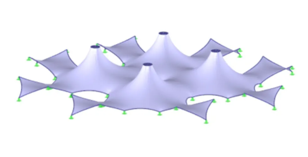
Question: Perform Form-Finding and structural analysis structure of multiple masts.
Solution:
AIM: To perform the form-finding and structural analysis structure of multiple masts in the software called REFM software.
PROCEDURE:
- So the very first step in order to perform the form-finding and the structural structure of multiple masts in the software.
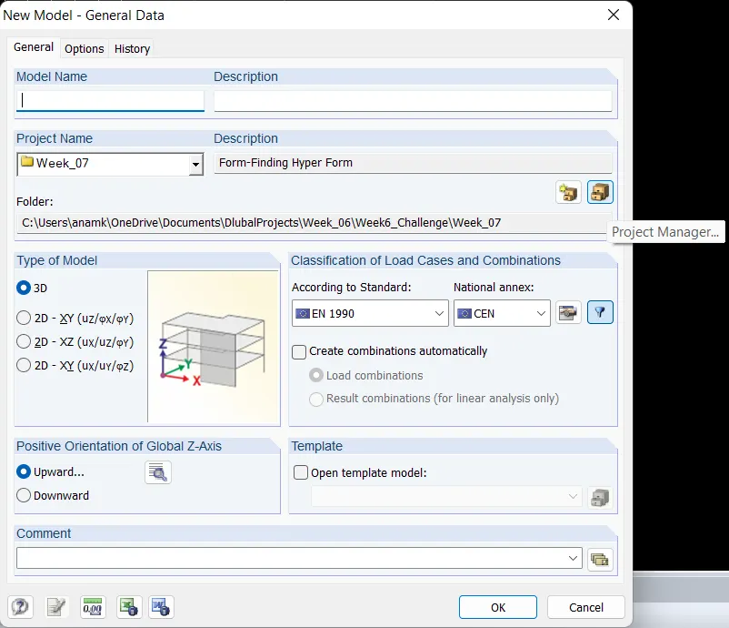
- First open the RFEM software and select new file and a new dialogue box is appeared named as the New Model-Gneral Data and in that dialouge box there will be another option named as the Project Manager... just click on that option just as shown in the below as we can see in the below given image:
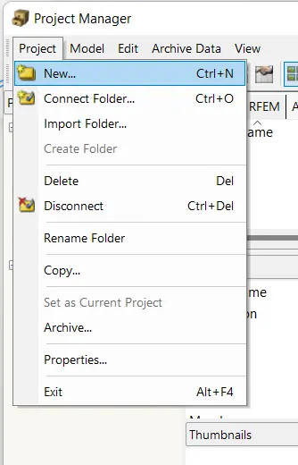
- Next there will be another dialouge box named as the Project Manager and in that dialouge box there will be another option named as the Project just click on that tab then there will be a drop-down list and in that list there will be another option named as the New just click on that option just as shown in the below given image:
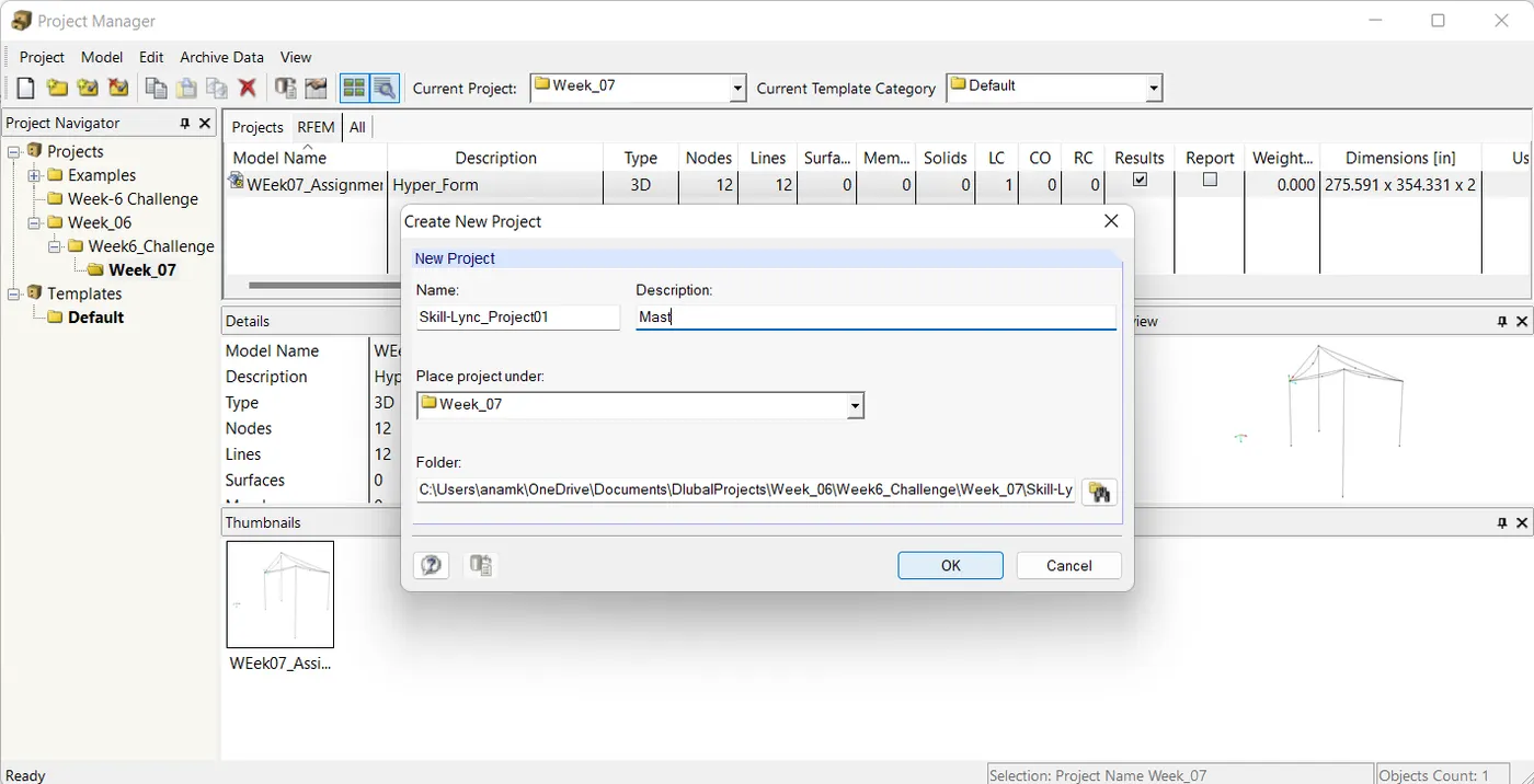
- Next there will be another dialouge box named as the Create New Project and in that dialouge box fill out the all necessary details just as shown in the below given image:
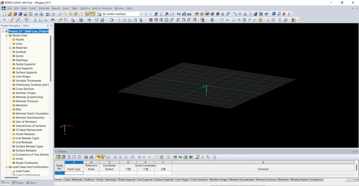
- New file has been created just as shown in the below given image:
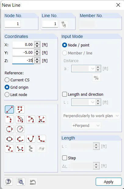
- Next we will be creating the nodes in order to draw a line and in order to draw a line we will be using the line tool and in order to create a line there will be an option named as the Line present at the top ribbon just click on that option just as shown in the below given image:

- Next there will be another dialouge box named as the New Line and give the units just as shown in the below give image:
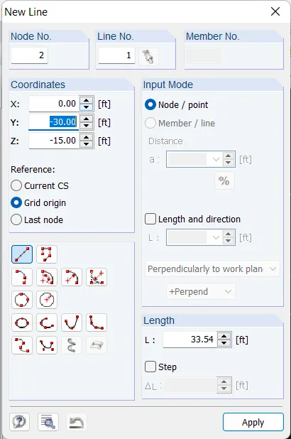
- The line has been created as shown in the below given image:
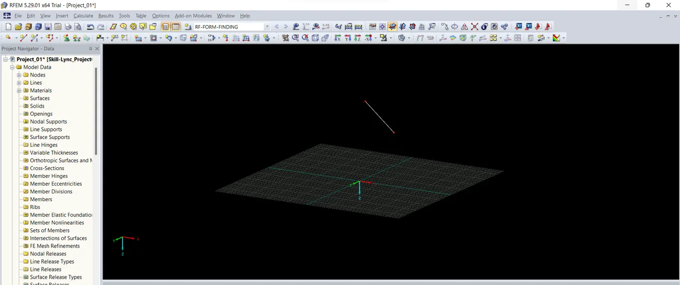
- Now we need to create a cone and in order to do that we need to select the line and a rotate option and to create a cone there will be an option named as the Rotate just click on that option which is available at the top of the screen as shown in the below given image:

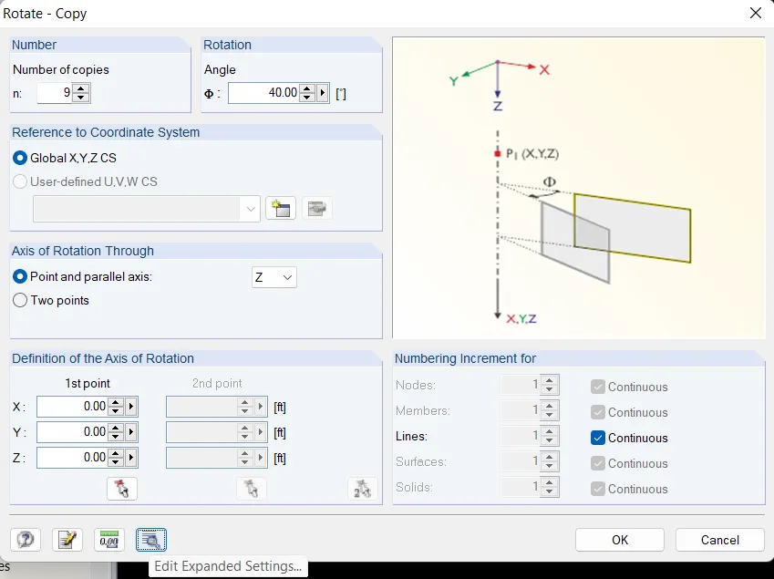
- Next there will be another dialouge box named as the Rotate and fill out the all necessary details just as shown in the below given image:
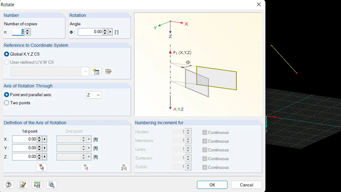
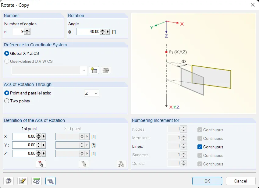
- Next there will be another option at the bottom of the dialouge box named as the Edit Expanded Settings click on that option just as shown in the below given image:
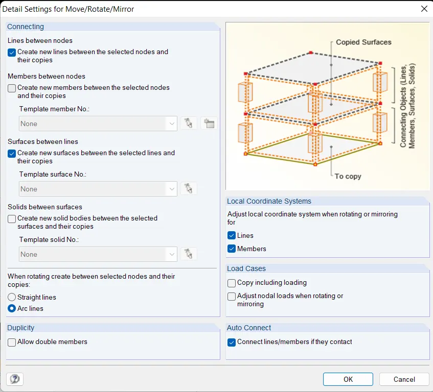
- There will be another dialouge box named as the Detail Settings fo r Move/Rotate/Mirror and tick the options just as shown in the below given image:
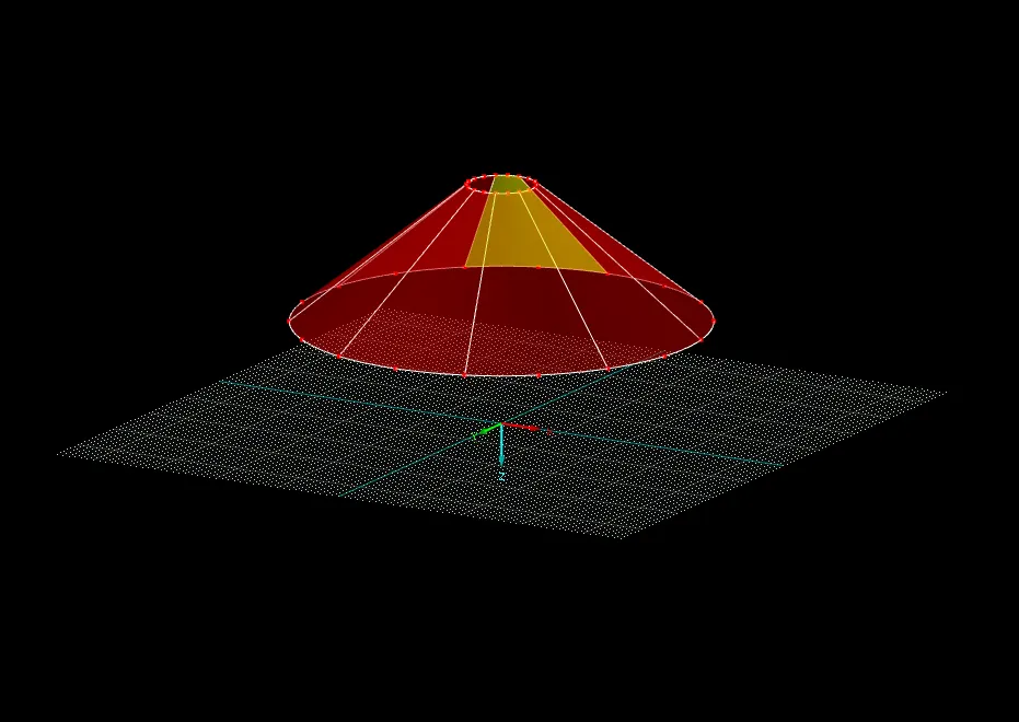
- Below is the image after creating the cone using the rotate tool we can see in the below given image:
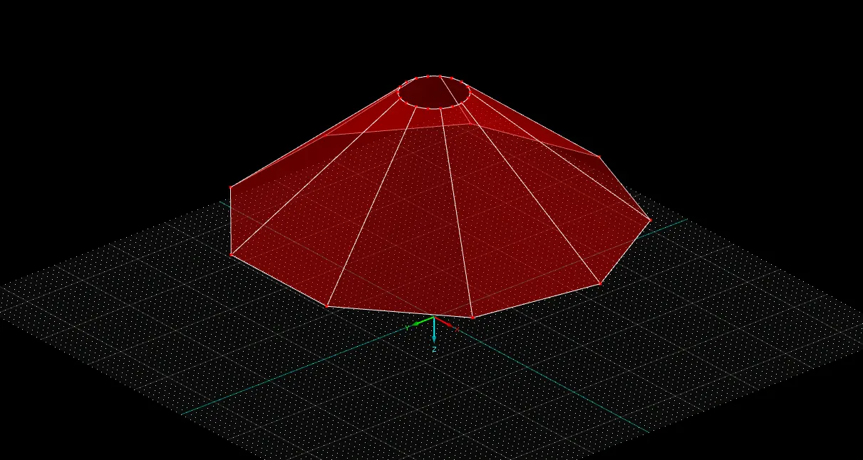
- Next makes the line into the polylines and in order to do that there will be an option named as the Line at the bottom of the screen just click on that option just as shown in the below given image:

- After creating the polylines we can see in the below given image:
- Next we will be mirroring the cones and in order to copy the cone there will be an option named as the copy which is present at the top of the bar just click on that option just as shown in the below given image:

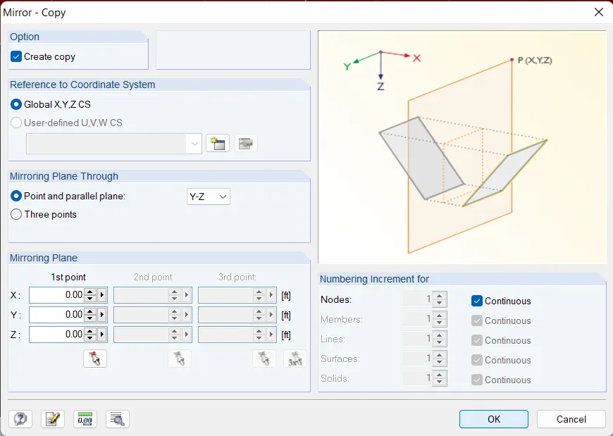
- Next there will be another dialouge box named as the Mirror then create the mirror as we can shown in the below given image:
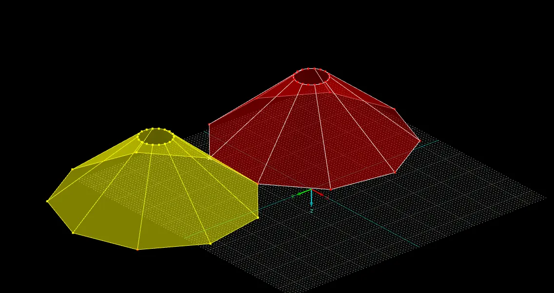
- Below is the image after mirroring the cones just as shown in the below given image:
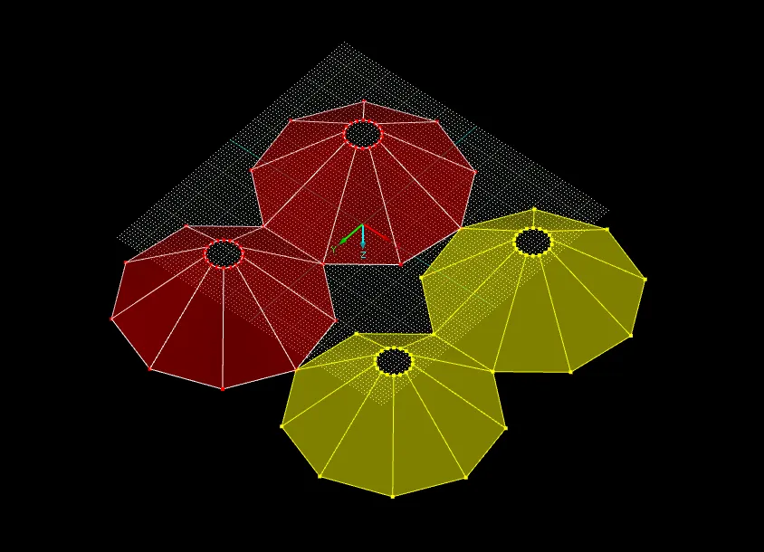
- Next again do the mirroring just as shown in the below given image :
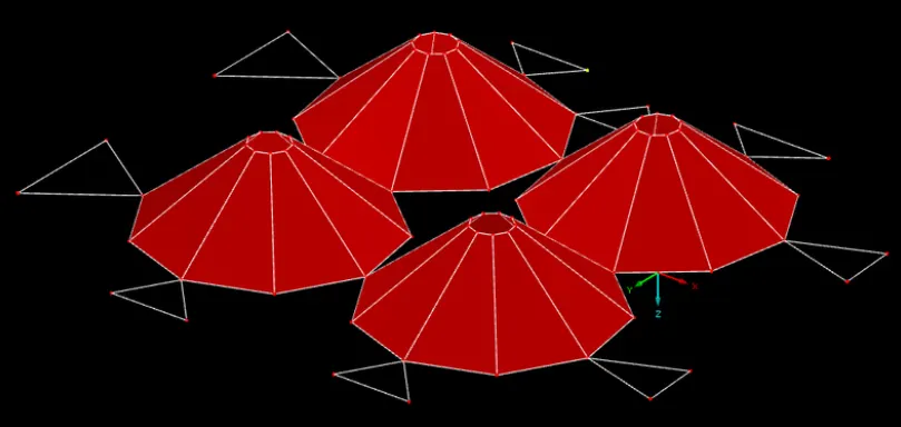
- Next we will draw the side support by using the line tool just as shown in the below given image:
- Next we will assign the surface to the roof and in order to do that go to the Insert ribbon tab click on that option then there will be a drop-down list and in that list there will be an option named as the Model Data just click on that option.
- Again click on that option then there will be another drop-down list and in that list there will be another option named as the Surfaces just click on that option next there will be another drop-down list and in that list there will be another option named as the Quadrangle click on that option.
- Then again click on that option there will be another drop-down list and in that list there will be an option named as the Graphically... just click on that option as shown in the below given image:
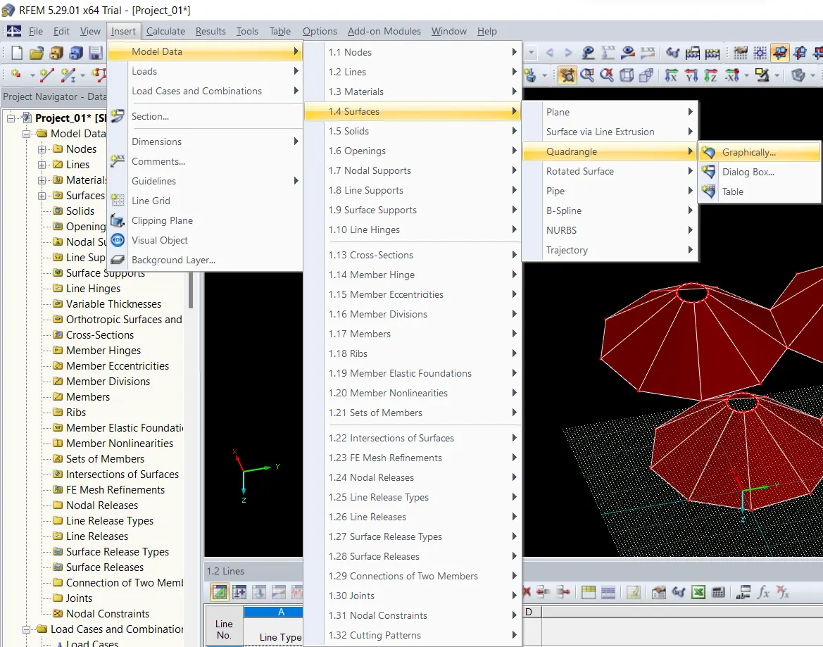
- Then there will be another dialouge box named as the Edit Surface fill out the all details just as shown in the below given image:
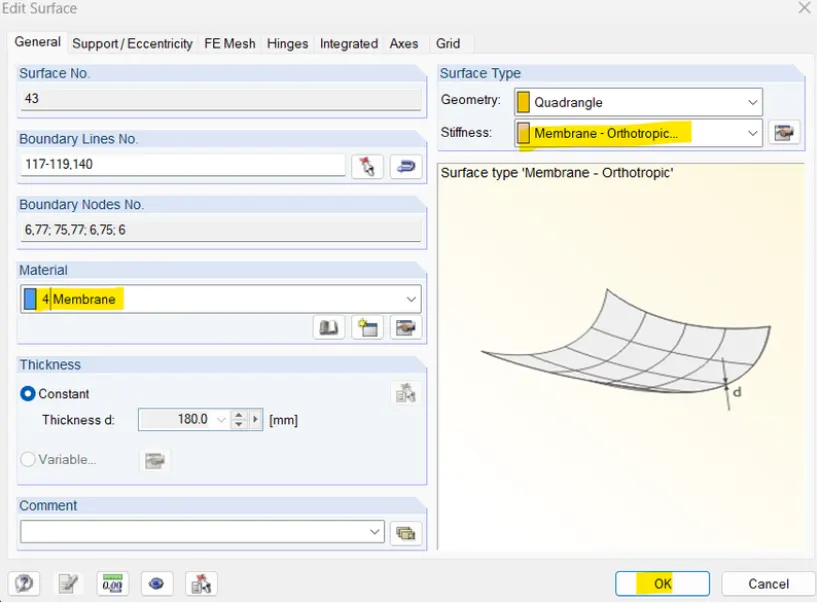
- Next select the line then double-click on that line then there will be another dialouge box named as the Edit line and in that dialouge box there will be an option named as the Available tick on that option just as shown in the below given image:
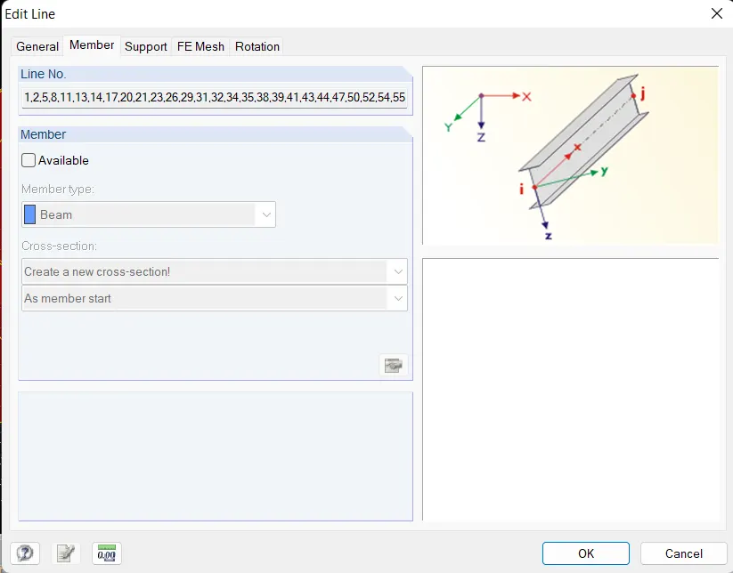
- After that there will be another dialouge box named as the New Member and in that dialouge box apply the materials and to that there will be another option named as the Import from Cross-Sectio Library... just click on that option as shown in the below given image:
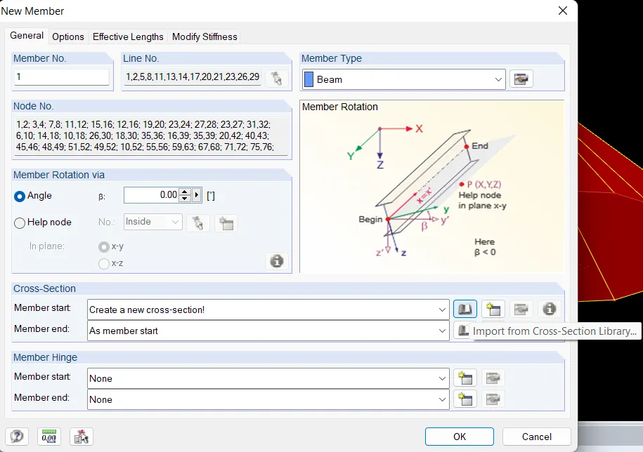
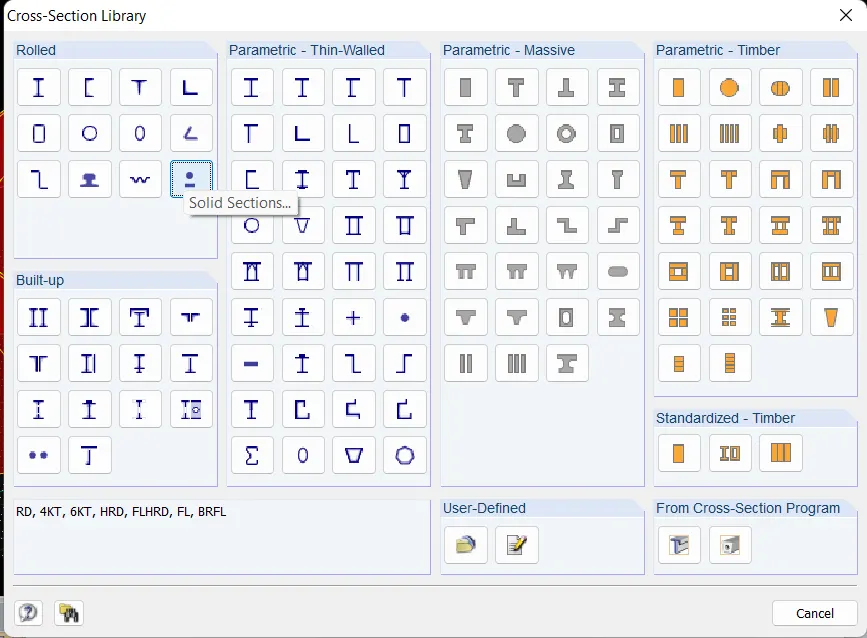
- Next there will be another dialouge box named as the Cross-Section Library and in that dialouge box select the section as Solid Sections... click on that option just as shown in the below given image:
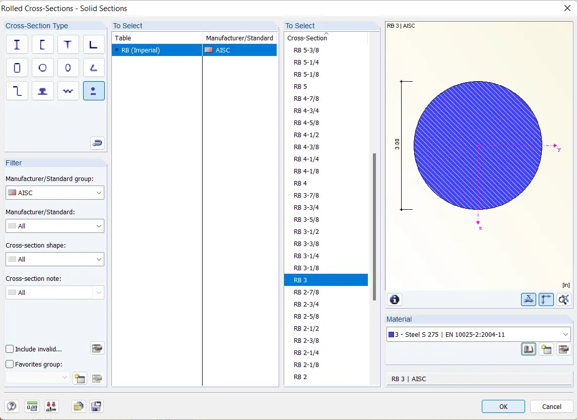
- Next there will be another dialouge box and in that dialouge box select the materials and apply them to the sections just as shown in the below given image:
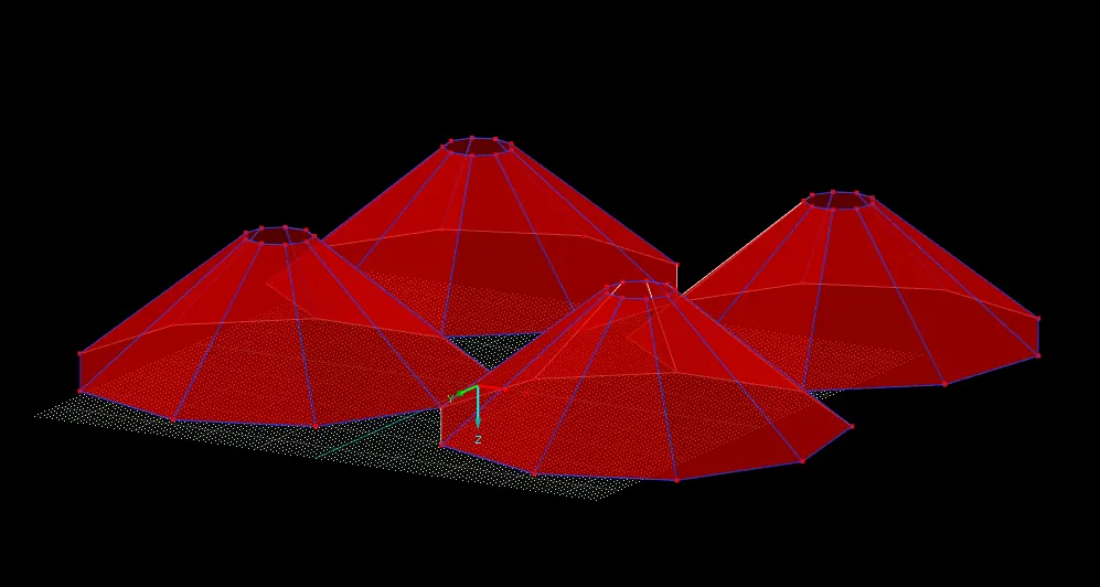
- Below is the image of the structure after applying the materials to the top and the bottom members:
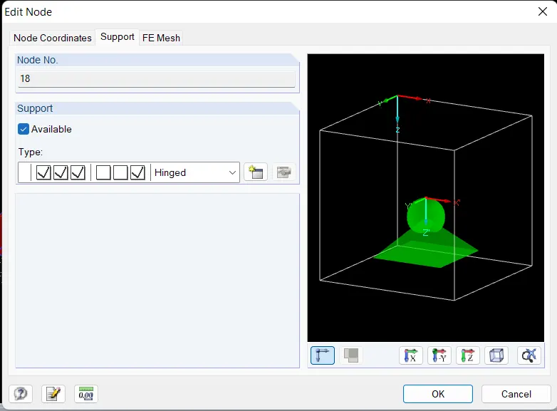
- Next we will be providing the support and in order to assign the supports just select the nodes and double click on that node, then there will be another dialouge box named as the Edit Node and in that dialouge box there will be another option named as the Support just click on that and then there will be another option Available tick on that option just as shown in the below given image:
- Below is the image after applying the supports as we can see in the image:
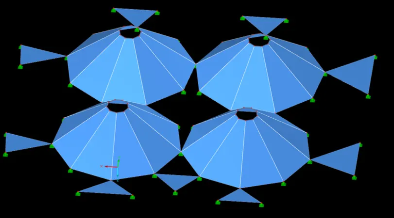
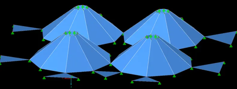
- Next assign the supports at the top of the membranes, and in order to assign the support do the same procedure as shown in the above process just as shown in the below given image:
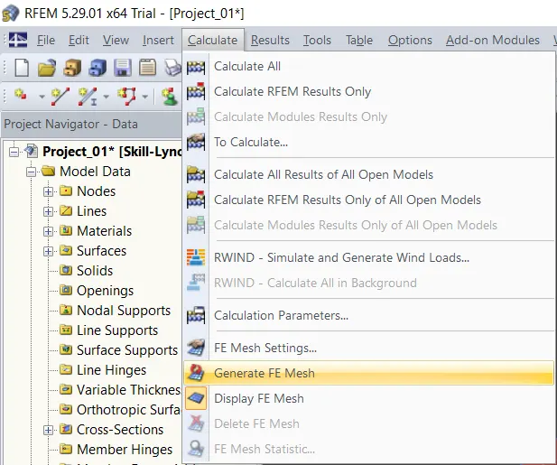
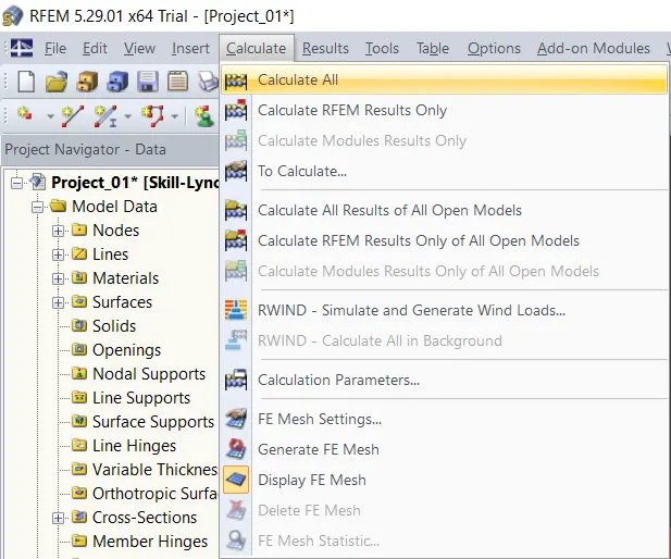
- Next we will be creating a mesh and in order to create a mesh just go to the Calculate tab then click on that option then there will be a drop-down list and in that list there will be an option named as the Generate FE Mesh just click on that option just as shown in the below given image:
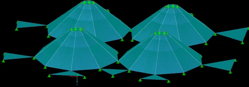
- Next and the last step is to do the calculations and in order to do that just go to the Calculations tab click on that option then there will be a drop-down list and in that list there will be an option named as the Calculate All just click on that option just as shown in the below given image:
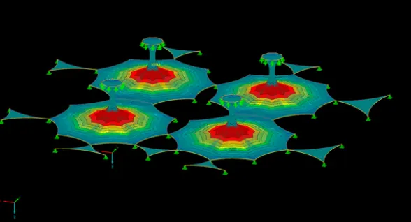
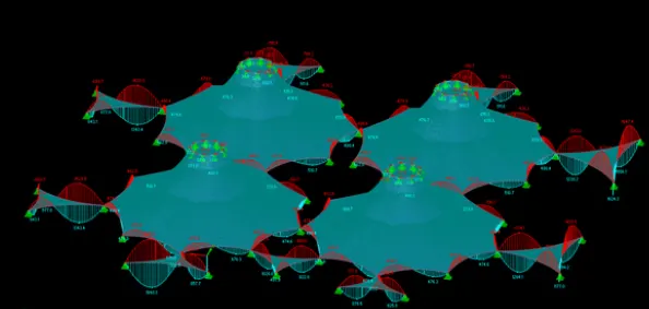
- Below is the image of the calculations as we can see in the below images: