Project 1
Aim :
- Develop a double-acting actuator model using Simscape Multibody and Simscape components.
Description
The Double-Acting Hydraulic Cylinder block models a device that converts hydraulic energy into mechanical energy in the form of translational motion. Hydraulic fluid pumped under pressure into one of the two cylinder chambers forces the piston to move and exert force on the cylinder rod. Double-acting cylinders transfer force and motion in both directions.
Double acting hydraulic cylinders
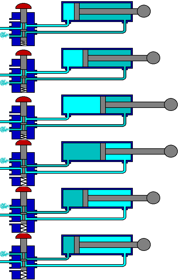
Symbol of double acting hydraulic cylinder
Differential type hydraulic cylinders:
Differential type is the most common type of hydraulic cylinder. It has two pistons; one connected to the rod and the other connected to the body. As the input force increases, the rod extends. At the same time, the body remains stationary because the second piston is locked into the cylinder. This causes the output force to increase. As the input force decreases, the rod retracts. At the same time, the body remains stationary because the second piston is locked into the cylinder. This causes the output force to decrease. The body will always remain in its original position as long as the input force is equal to the output force. However, the rod will move up or down depending on which one of the two forces is greater. Therefore, a differential type hydraulic cylinder is very useful. For example, if you want to raise a heavy box, you should use a rod connected to the body of the cylinder. Make sure that there is a safety factor so the force exerted by the rod is always greater than the weight of the object being lifted.
Synchronous type hydraulic cylinders:
Synchronous type cylinders work on a different principle. Instead of oil pressure, an electrical signal is sent to a valve that allows the oil to enter the cylinder and keep the piston moving up and down. When the signal is stopped, the oil stops flowing into the cylinder and the piston comes to a stop. This makes the cylinder very efficient in terms of power usage.
Synchronous type hydraulic cylinders have only one piston. This piston will expand and contract at the same time regardless of the amount of hydraulic fluid that is inside the cylinder. This makes this type of cylinder very efficient but not as powerful as the other type. You will find this type of hydraulic cylinder mainly used on automobiles, farm equipment, and industrial machinery.
Model
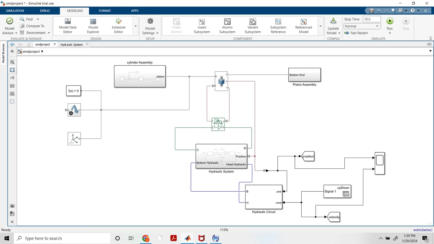
In chamber A, a tension at port A maneuvers the cylinder from 0 to stroke length. The dislodging of the cylinder equivalents to the position result of the Prismatic Joint block. To show chamber A:
Associate the ports C and R of the Translational Multibody Interface block to the ports C and R of the upper Translational Mechanical Converter (IL) block, individually.
In the Translational Mechanical Converter (IL) block, set Interface removal to Provide input signal from Multibody joint to empower port p.
Interface ports p of the Prismatic Joint block and Translational Mechanical Converter (IL) block.
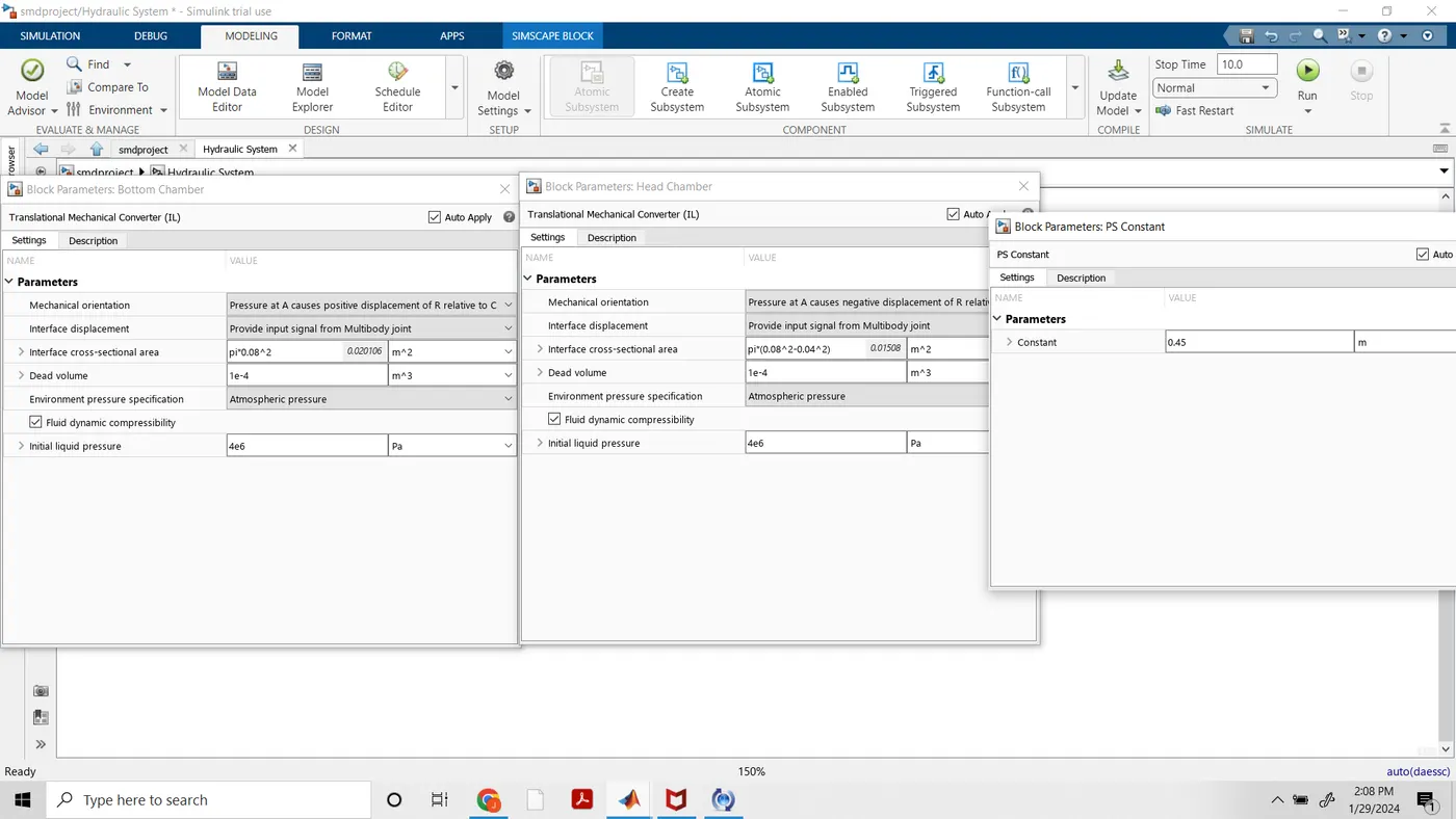
In chamber B, the strain at port A maneuvers the cylinder from 0 to negative stroke length. Subsequently, you really want to change the default direction and add an offset to the information position sign of the lower Translational Mechanical Converter (IL) block. The offset approaches - dB.
In the lower Translational Mechanical Converter (IL) block, set Mechanical direction to Pressure at A makes negative dislodging of R relative C.
Set Interface uprooting to Provide input signal from Multibody joint to empower the port p.
Add a PS Constant block and indicate the steady as the stroke length of the chamber.
Add a PS Subtract block, then associate it to the PS Constant and Prismatic Joint blocks as displayed in the graph. Note that the result of the PS Subtract block rises to - dB.
To restrict the movement of the cylinder:
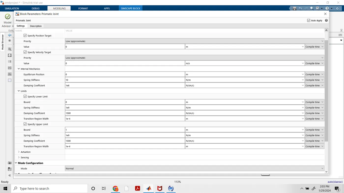
In the Prismatic Joint block, under the Limits segment, select the Specify Lower Limit and Specify Upper Limit boundaries.
Under the Specify Lower Limit area, the Bound boundary shows the base distance between the edges B and F of the joint block. In this model, determine the Bound boundary as 0 m.
Under Specify Upper Limit, the Bound boundary shows the greatest distance between outlines B and F of the Prismatic Joint block. In this model, determine the Bound boundary as the stroke length of the chamber.
Twofold acting chamber frameworks can be utilized in numerous applications. For instance, a dump trailer can utilize a twofold acting chamber to incite a scissor lift instrument that raises and brings down the landfill bed. See Hydraulic Interface - Dump Trailer with Hydraulic Cylinder (Simscape Multibody) for additional subtleties. Under the cover of the Double-Acting Hydraulic Cylinder block in the scissor raise are the mechanical and water driven subsystems, which are associated by a Translational Multibody Interface block. The Prismatic Joint block in the mechanical subsystem gives the position data to the two actuators in the pressure driven subsystem, Head Chamber and Bottom Chamber, that have the contrary settings of the Mechanical direction boundary. The Constant block C gives a position signal offset to the Head Chamber actuator, since when the Bottom Chamber is at dead volume (where position p = 0), the Head Chamber is at most extreme stroke.
In mechanial system two subsystem are taken 1.cylinder Assembly 2. piston Assembly
Cylinder Assembly
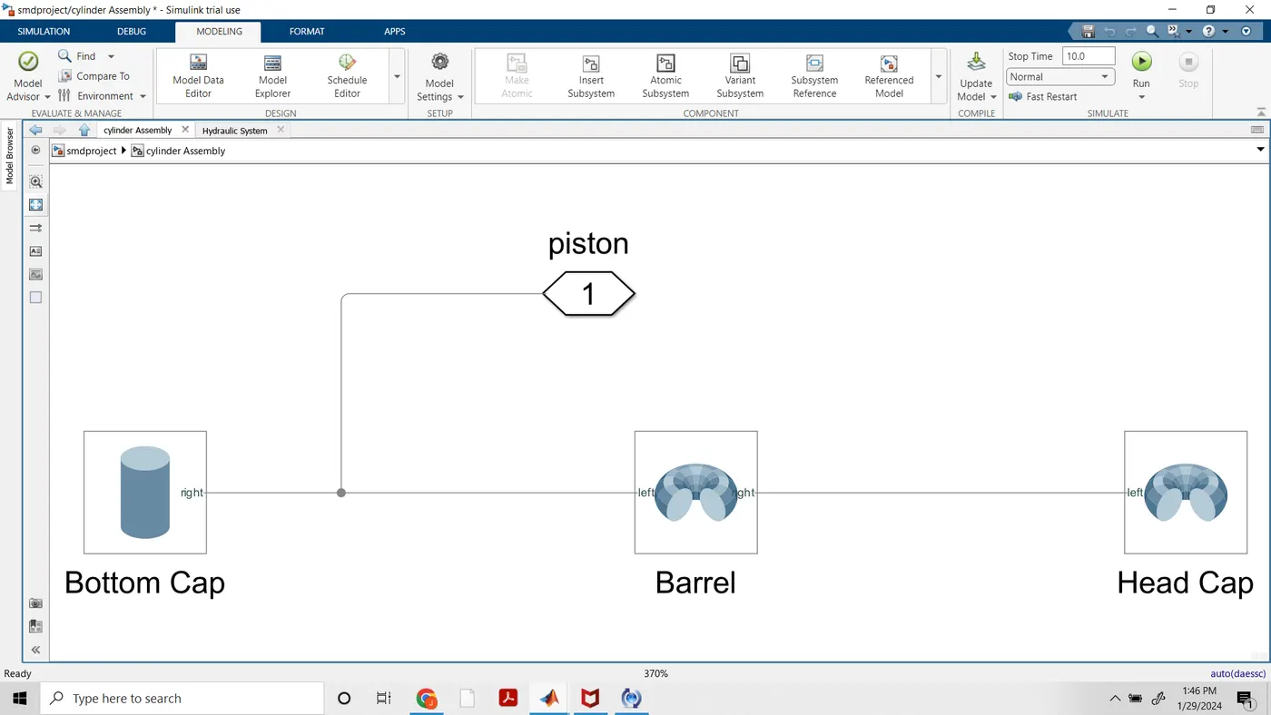
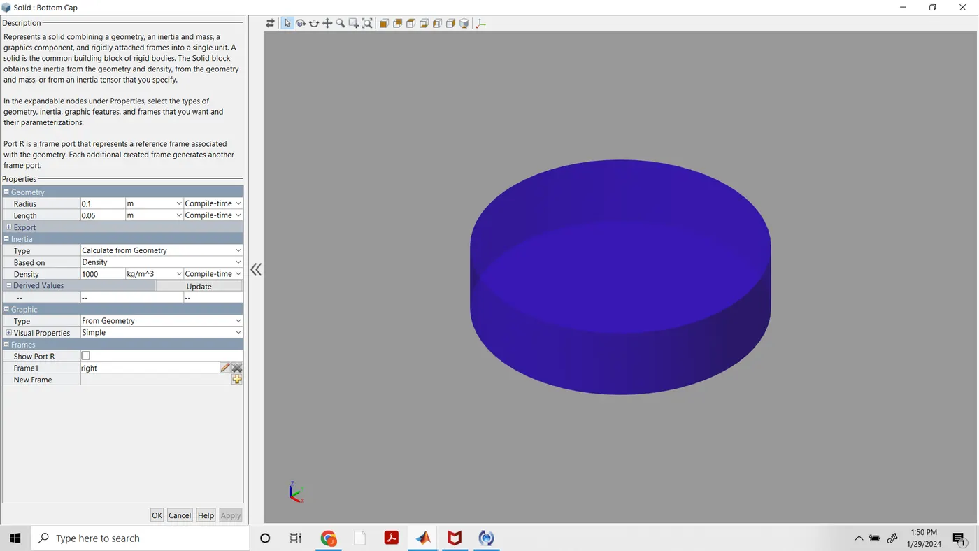
BottomCap
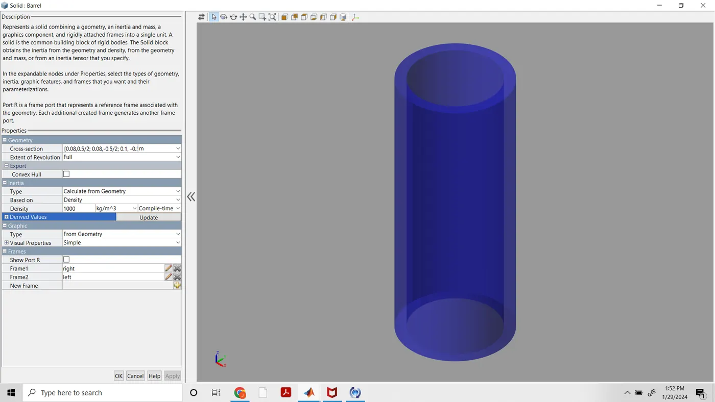
Barrel
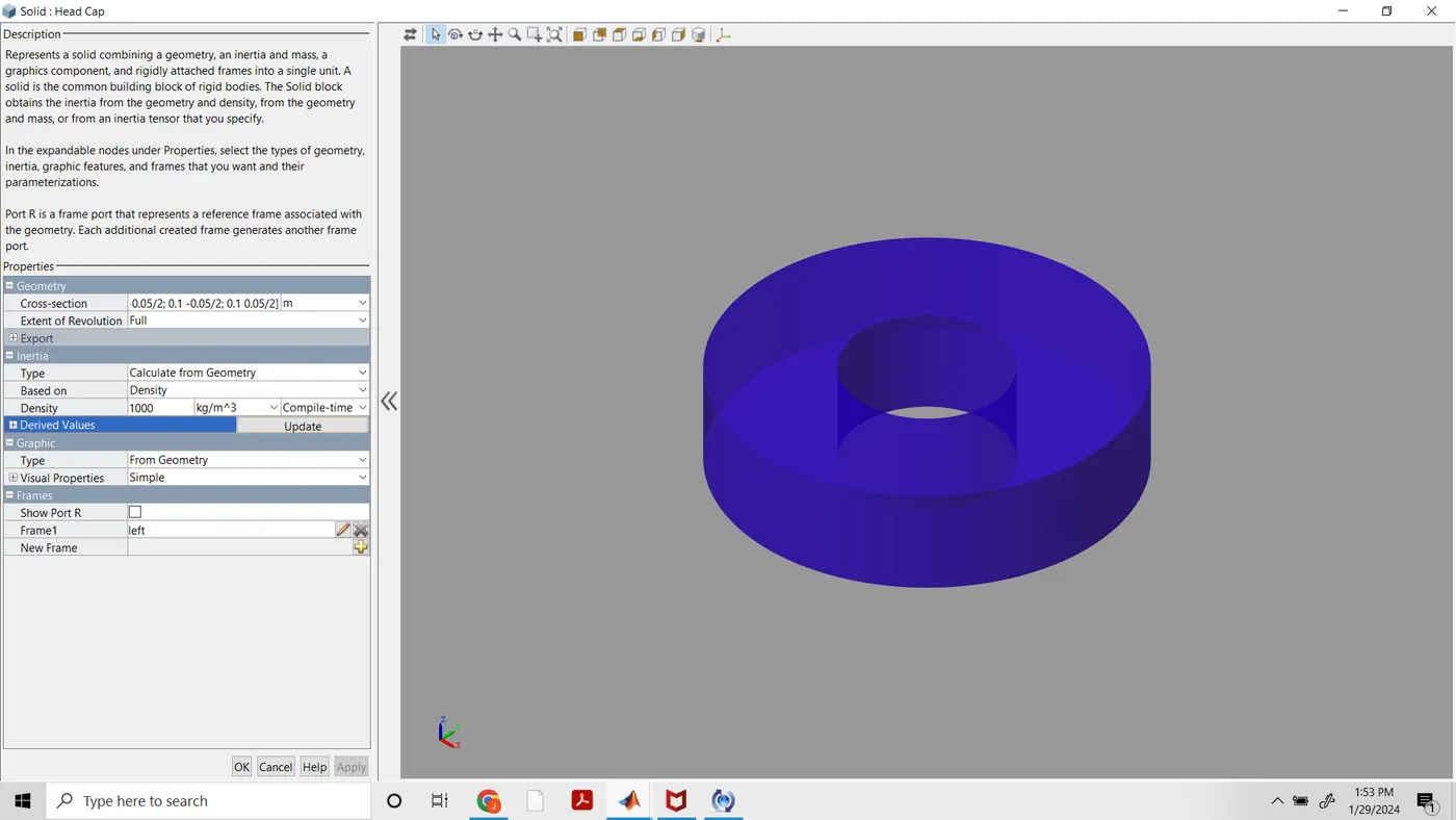
Head Cap
Piston Assembly
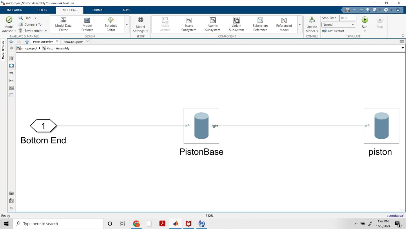
Piston Base
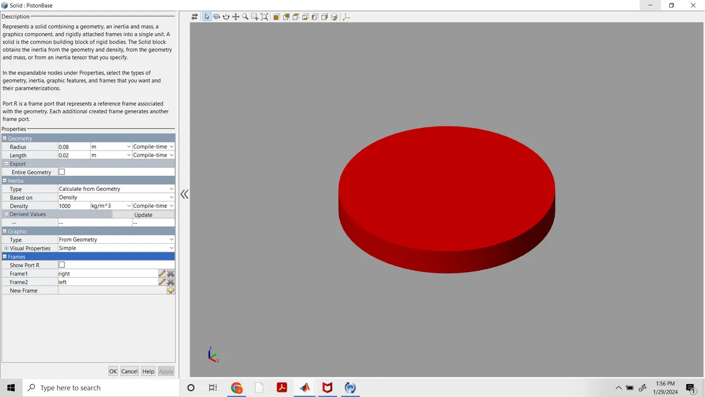
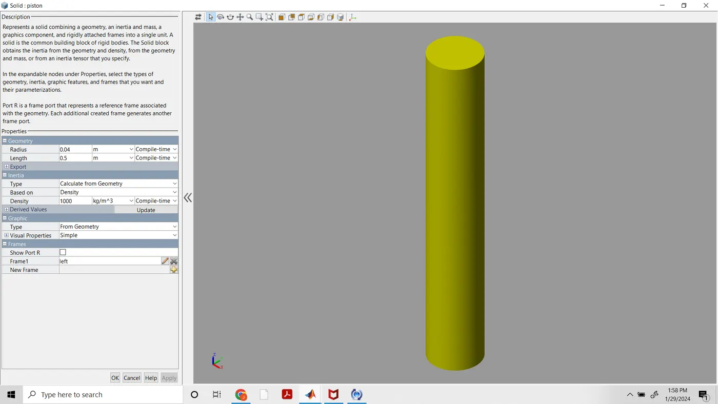
Piston
- Prismatic Joint:
A prismatic joint is often called a slider — for example, a “crank-slider linkage.” This is a type of kinematic pair and an idealized way to describe how motions are constrained within machines.
There are several physical embodiments of a prismatic joint, such as slideways. Rectangular cross-sections may be used in combination with plain or rolling bearings to enable linear motion while preventing rotation about the axis of movement.
Hydraulic and pneumatic cylinders are typically modeled as prismatic joints although they may also permit rotation about their axis. Kinematic pairs are classified as higher pairs and lower pairs. Higher pairs involve point or line contact, such as a ball or roller that’s rolling over a surface. Lower pairs can be visualized as surface contact.
- Hydraulic System
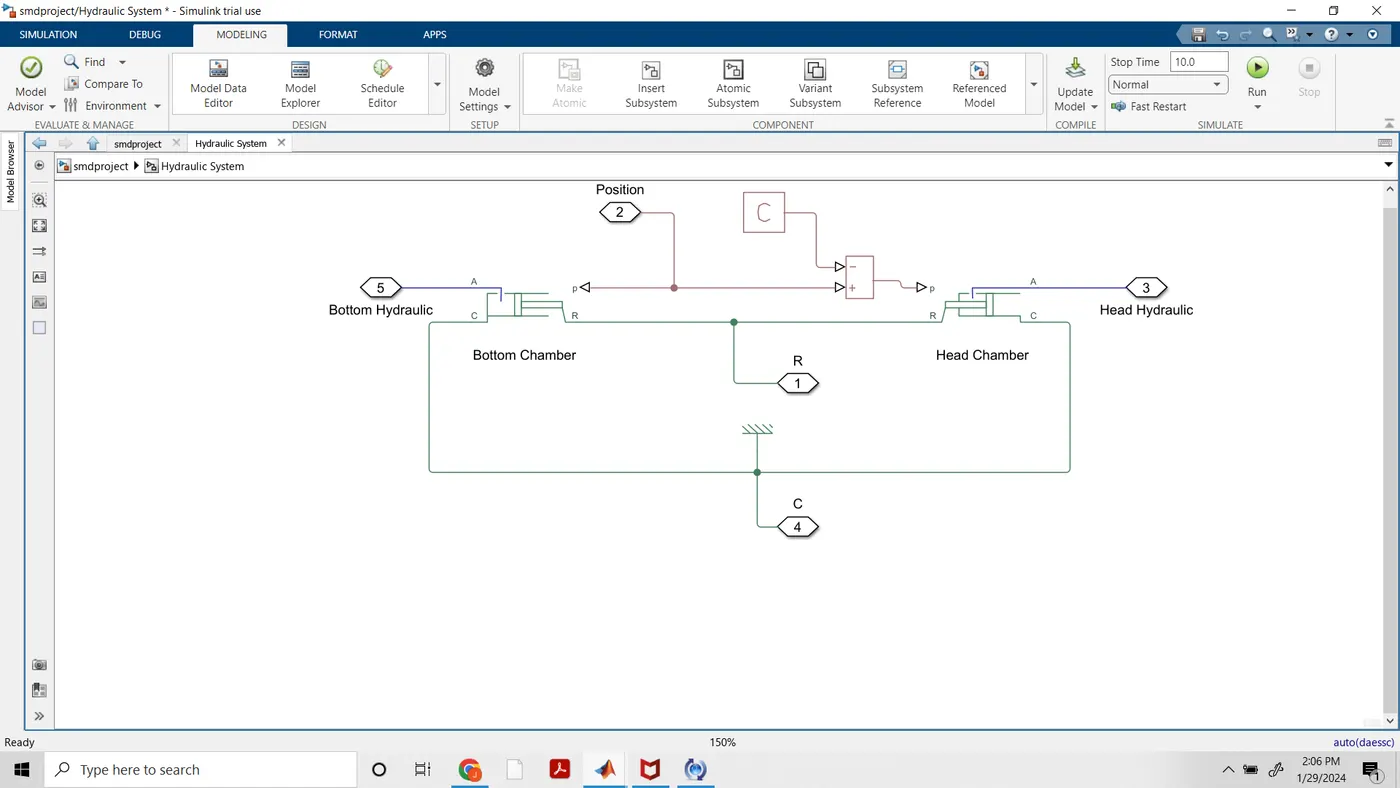
- following setting done in bottom chamber and head chamber block. Ps constant is set to 0.45 m.
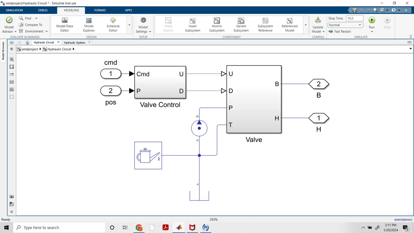
- Hydraulic Circuit:
- This is reffer from given link drump trailer example
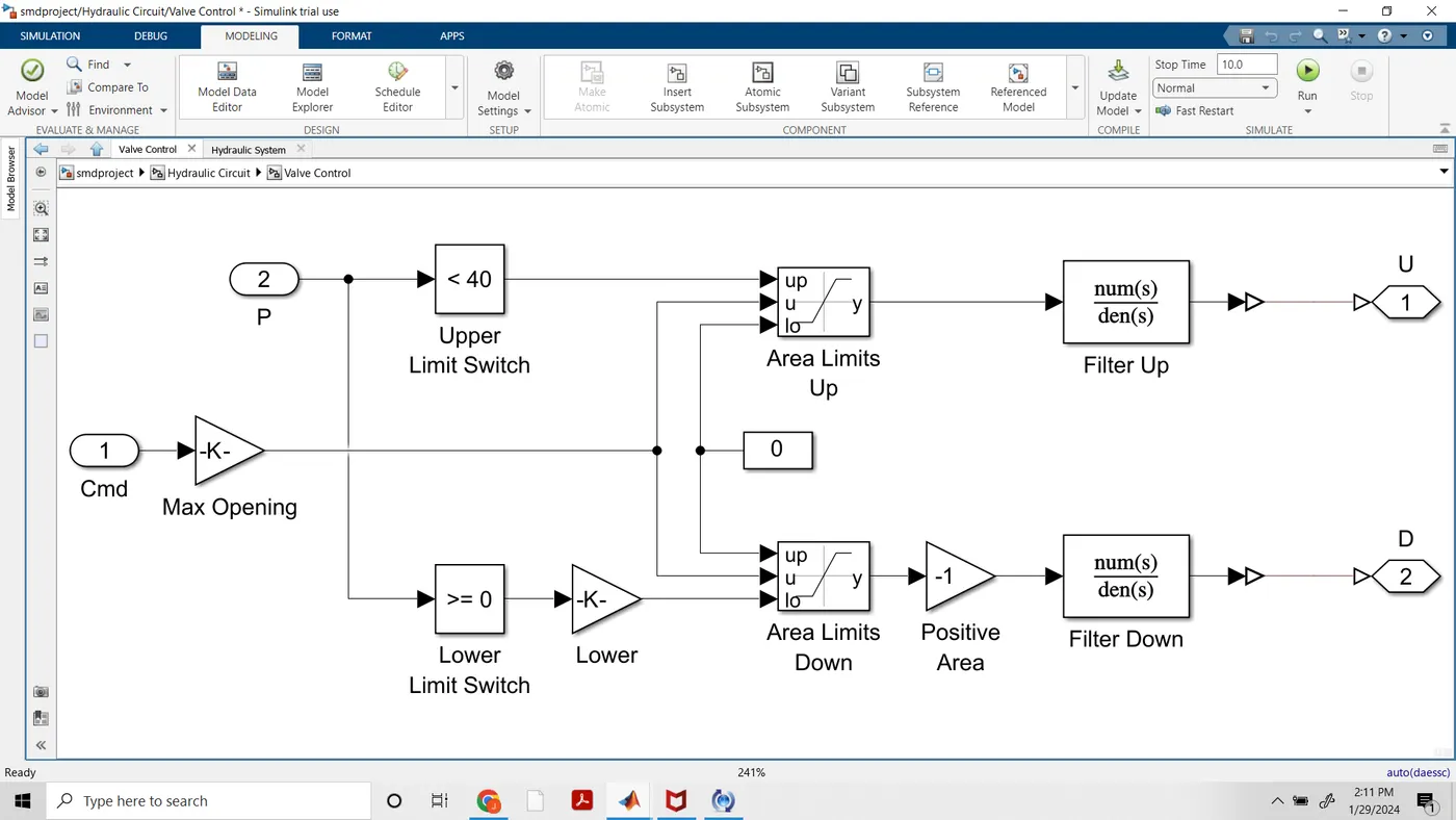
- Valve Control:
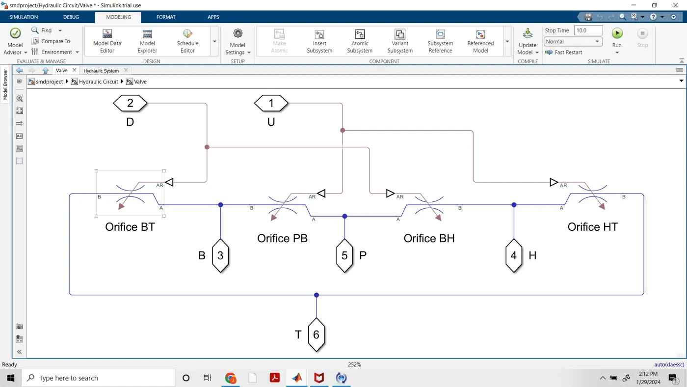
- Valve
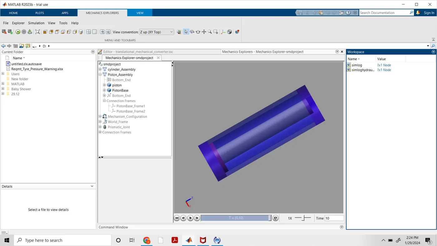
- we get following explorer of hydraulic cylinder: