Project 1
WIRING HARNESS ROUTING AND FLATTENING ON V16 ENGINE
Aim:
To Design and develop the wire harness routing for the given V16 engine by following the design and packaging rules.
Objective:
- To Define all the connectors electrically and save it in the catalogue.
- To place all the connectors and cavities at the required positions.
- To place P Clamps and Fir tree Clips at the requried position by the following the packaging rules.
- To create the wire harness routing as per required and create branch points wherever requried and also by following the packaging rules.
- To create the wire harness Flattening of the above routing.
- To display the flattened view in the drawing sheet.
Design Methodology:
Step-1:
Create a product file as 'Engine Harness Assembly Context' in which all the part and product file will be assembled which are requried for the routing.
Step-2:
Create another product file as 'Engine Harness Assembly Geometrical Bundle' where all the connectors are added to it and the final routing is a part of this product file.
Step-3:
Now add the V16 Engine,Geometrical bundle file and other requried parts or products to our main 'Engine Harness Assembly Context' product file.
Step-4:
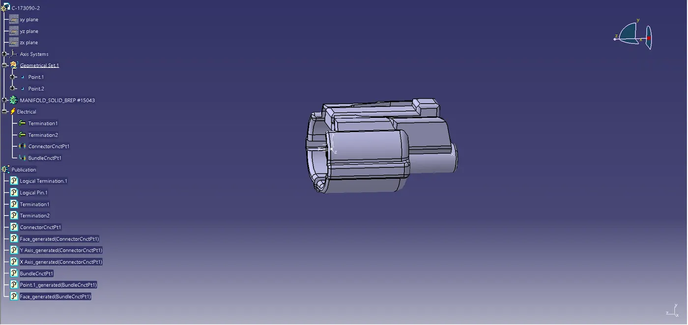
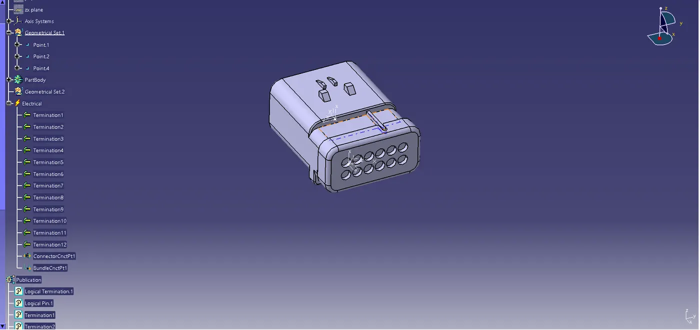
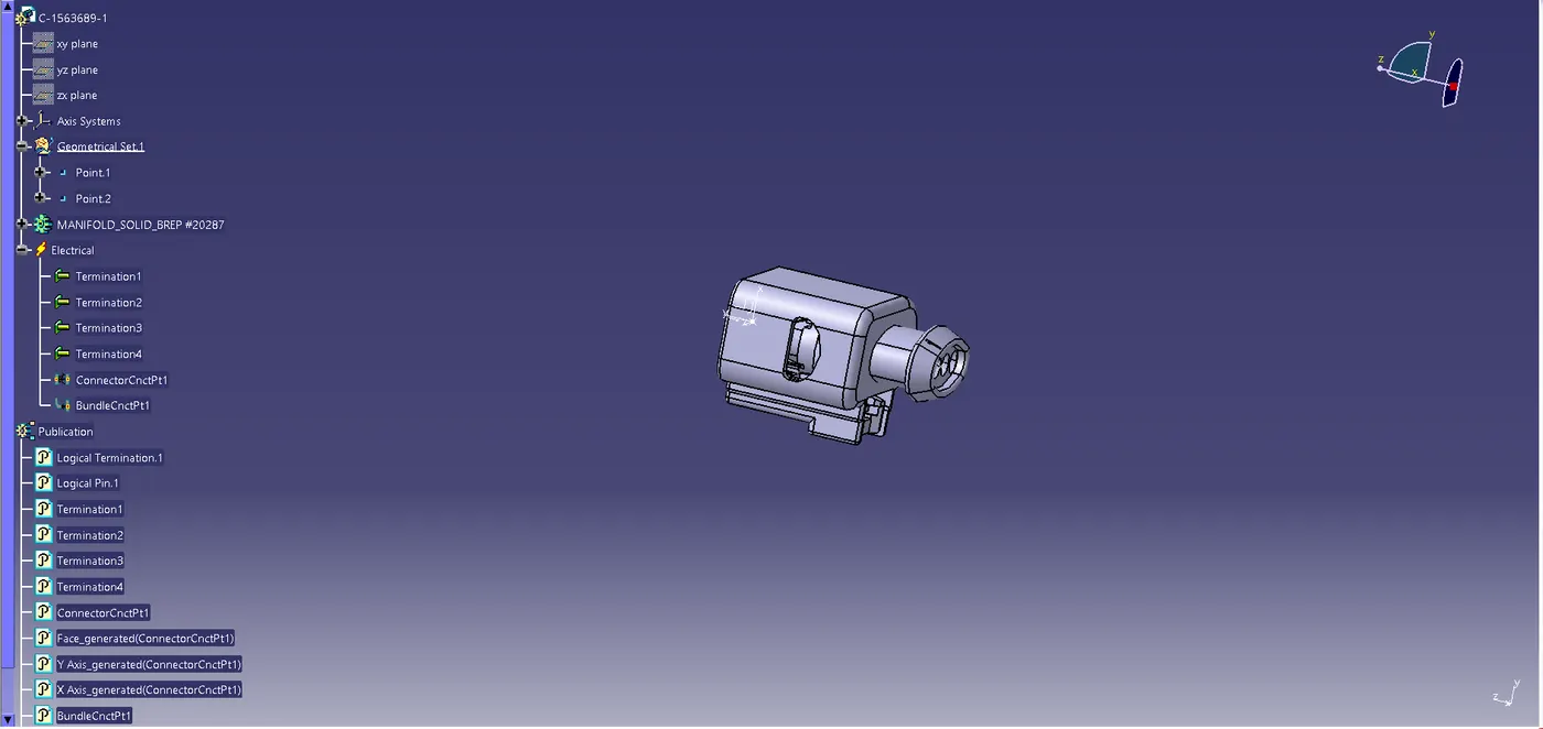
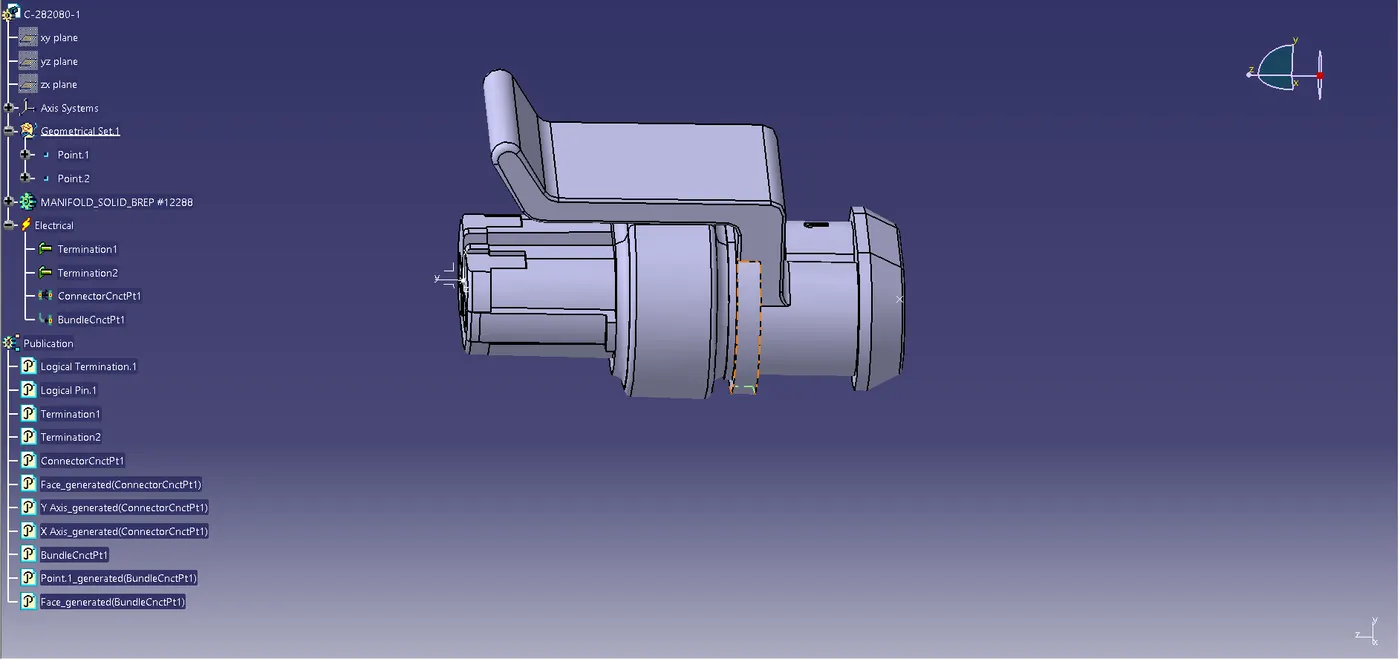
Electrically Define all the connectors,Cavity clips and channel part and define the connector connection point and Bundle connection point.
After elctrically defining each and every connector save it in the connector catalogue so that it can be used later.
Electrically Defined Connectors:
1.C-173090-2:
2.C-776438-4:
3.C-1563689-1:
4.C-282080-1:
5.C-1924487-2:
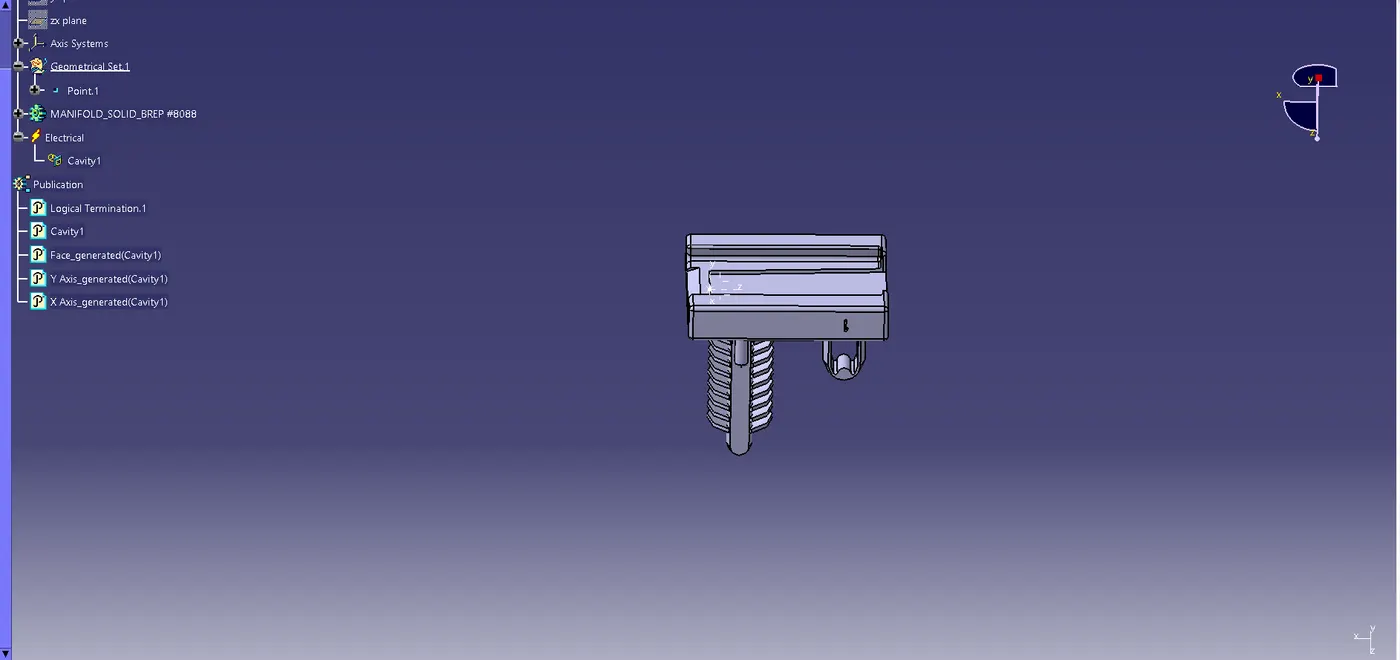
6.P-CLAMP:
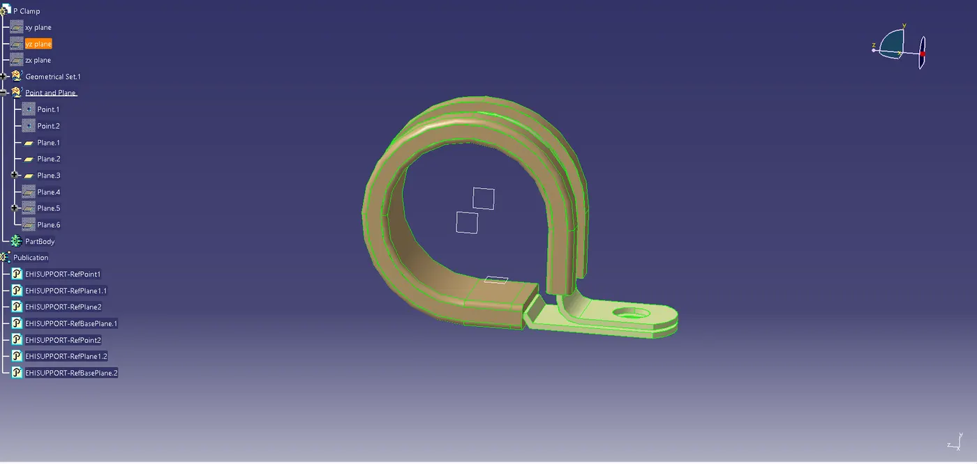
7.FIR TREE CLIP:
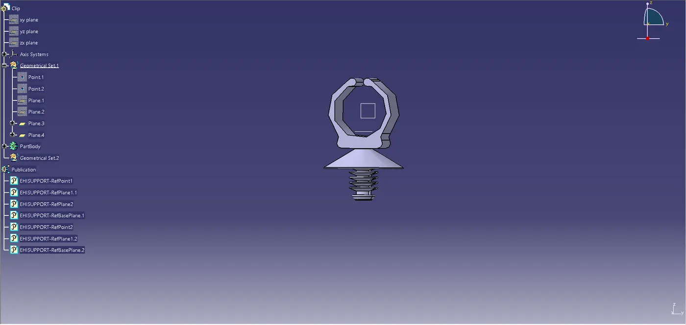
8.CONNECTING CHANNEL BOTTOM:
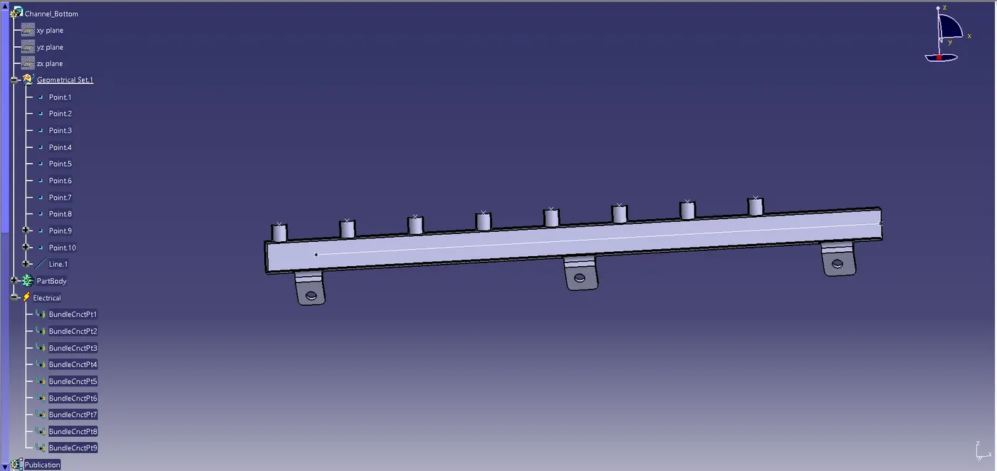
9.CONNECTING CHANNEL TOP:
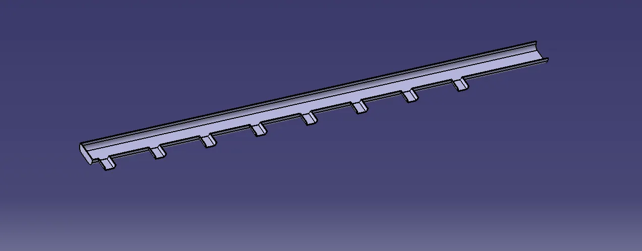
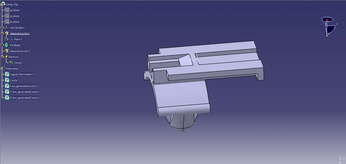
10.CAVITY CLIP:
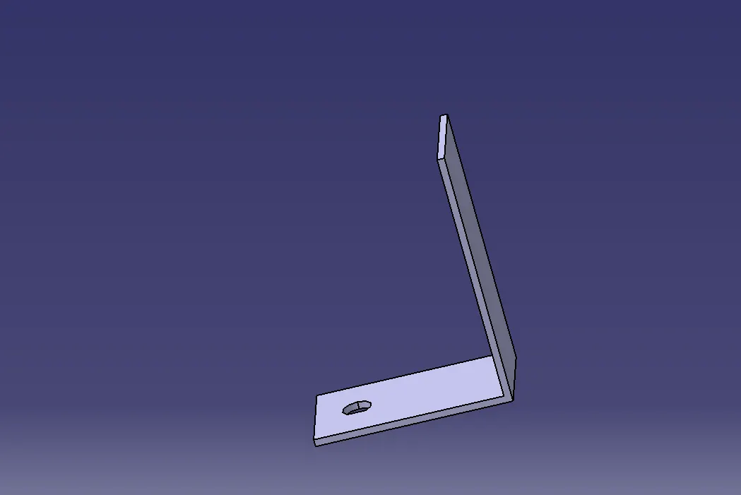
11.L-CLAMP:
Step-5:
- Add all the connectors to the geometric bundle product file and place them using the 'Smart move' or 'Manipulation Tool' command and the compass into thier desired locations.
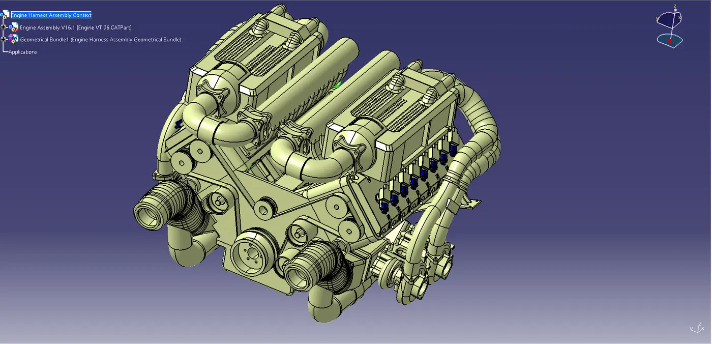
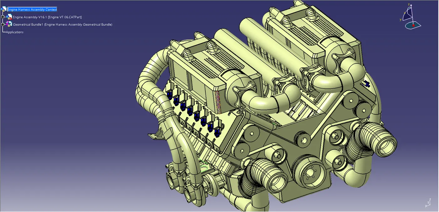
- Here in this V16 Engine:
- 8 Fuel injectors on each side.
- 2 Cam shafts sensors on each side of the cylinder block (2+2).
- 1 Engine coolant temperature sensor placed on the oil stamp of the engine on each side (1+1)
- Engine Oil temperature and pressure sensor placed at the oil sump of the engine on the each side (1+1).
- 1 Vehicle speed sensor at the Cylinder head block.
- 1 Neutral position of the transmission sensor at the cylinder Head Block.
- So all the connectors are placed according to thier specified location.
- During the placing of the connectors the important part is the placing of the interconnecting connector which will connect the engine wiring harness to the vehicle/Chasis wiring harness for the transfer of signal and data.
- In order to place and position the interconnecting connectors we need to find the proper place and also,we need to keep in mind that no thread can be drilled into the engine block because they are tightened using a proper torque wrench and if they are used on the engine blocks there will be sealing issues after tightening the screws
- To place the interconnection Connector on to our engine let us assume that the vehicle harness is on the right side of the engine then we can place the connector at the right side of the engine.
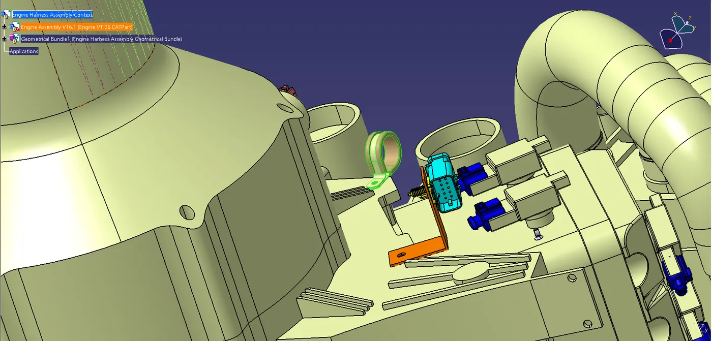
- As discussed above we cannot place the cavity clip onto the engine block so we can use one of the hole provided onto the engine casing to place our 'l-clip' on which we can place our interconnection connector.
- To Deecide the proper orientation of the L clip we need to consider that during tightening of the screw with a torque wrench the l clip may tend to rotate.So,we must place the L Clip in such a manner that the surrounding provides an obstruction or barrier to the movement of the L clip and it doesn't rotate during the tightening of the screws.
- The L Clip is mounted to one of the holes provide on the engine block for the screw and it is rested onto the ribs ,so that it restricts its rotational movement during tightening of the screw.
- And also,we can see that the Interconnection Connector have been placed and it is Electrically Connected with the cavity provided for it.
- The L-Clip should be added to the main product as it is not a part of the Geometric bundle or the wire harness bundle.
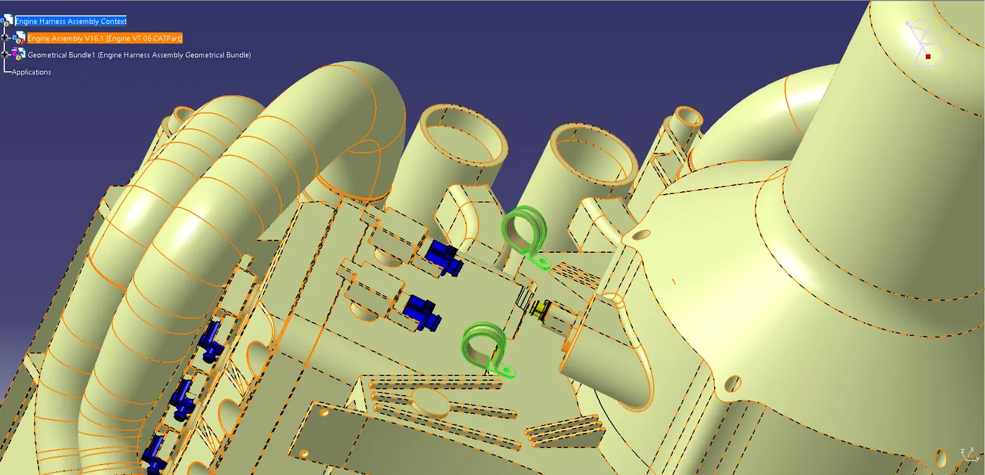
- To place the P Clamp and the Fir Tree in proper location which will be requried for the routing .
- The P clamps are mounted onto the holes on the Engine block which are provided for the screws to tighten the Engine block.
- The Fir tree clips are positioned according to the requirement during the wire harness routing.
- After finalization of the routing,we can request the engine design team tp provide the holes for the fir tree clips as per thier locations.
Some Important Packaging Rules to be Considered During Wire harness Routing and placing of the Clips and Clamps:
- P-Clamps,Fir tree Clips and other clips can be added to the Geometric bundle as they are electrically defined and are part of the wire harness routing and should be provided with the wire bundle package.
- The minimum bundle length should be 50mm.
- Enough Slack should be provided so,that the wiring harness do not get damaged during the engine rocking or starting conditions.
- The wire harness routing should be done in such a way that it is easy in manufacturing and serviceability.
- The wire routing should be done keeping in mind the cost effectiveness of the bundle package.
- To avoid the harness routing and clipping in blind zones of the operator during the assembly and the service.
- Additional slack should be given according to the surrounding and harness bending requriments.
- To avoid giving excess slack and avoid giving slacks wherever not necessary.
- To provide proper slack at end connectors so that there will be no tension on the wire bundle.
Keeping all the above packaging rules we can start the routing of the wire and provide clipping and clamping wherever necessary during the routing process.
Images of Harness Routing or Wre Routing and Conectors,Clips and Channel Mounting:
Connector Mountings:
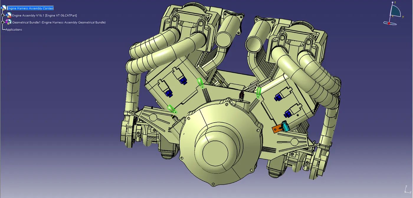
Connector Mounting On Fuel Injector Part:
L-Clamp Mounting:
P-Clamp Mounting:
Connecting Channel Bottom Mounting For Fuel Injectors:
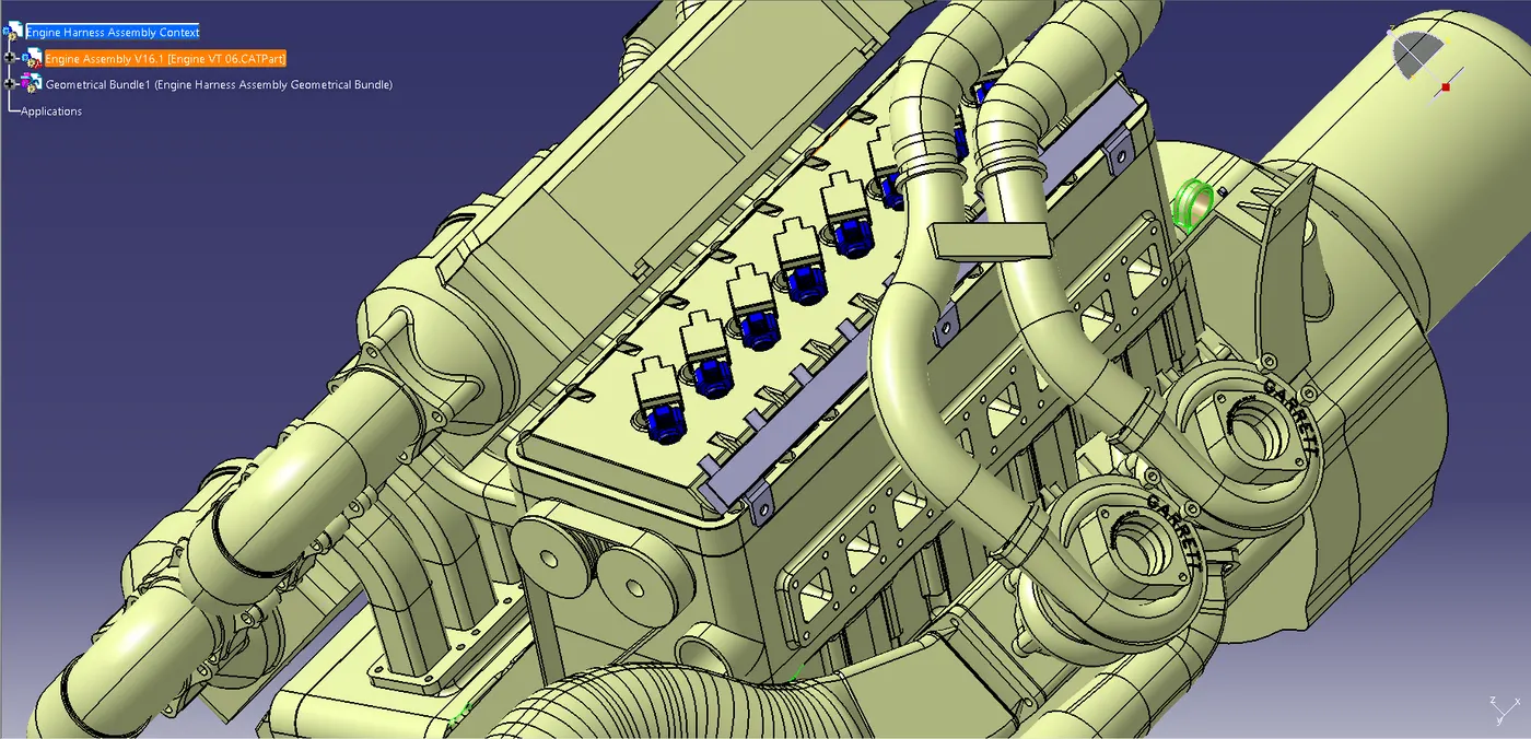
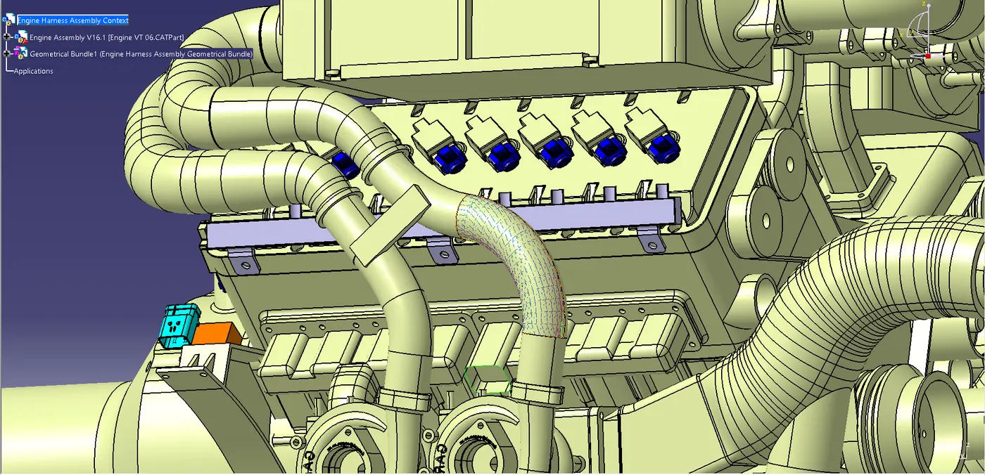
Connecting Channel Top Mounting For Fuel Injectors:
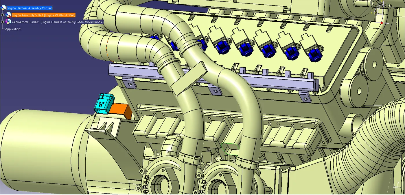
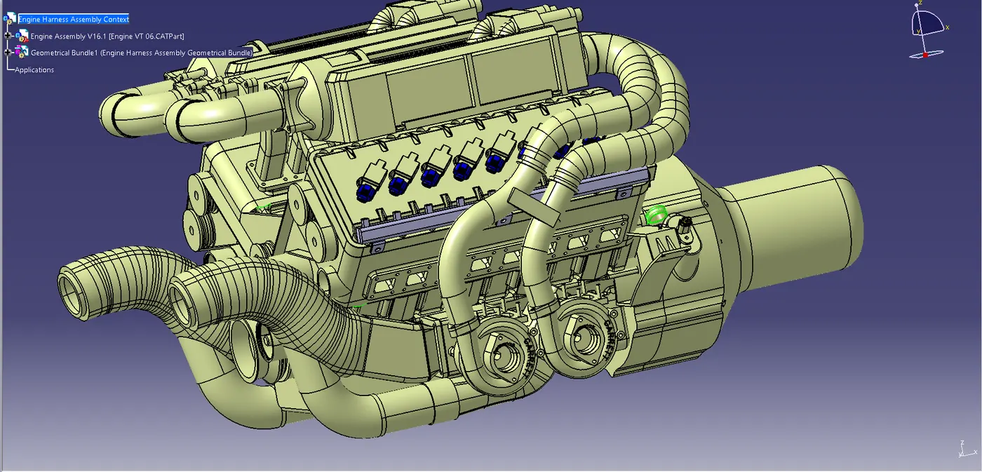
Harness Routing To Connector And Clips:
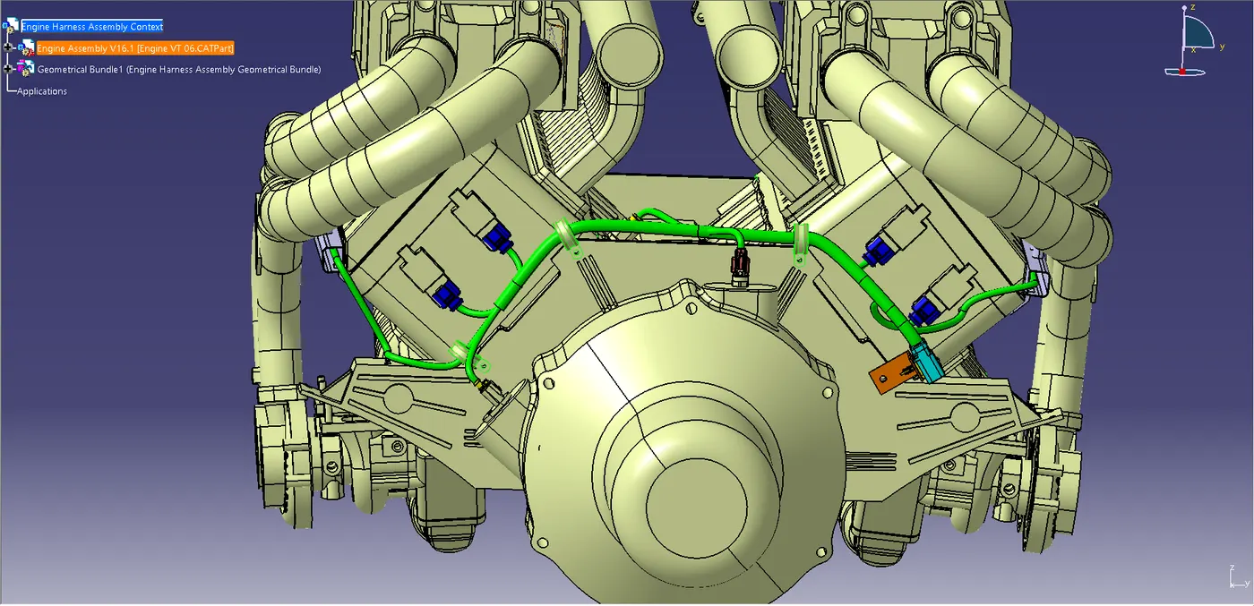
Routing for the Fuel Injectors:
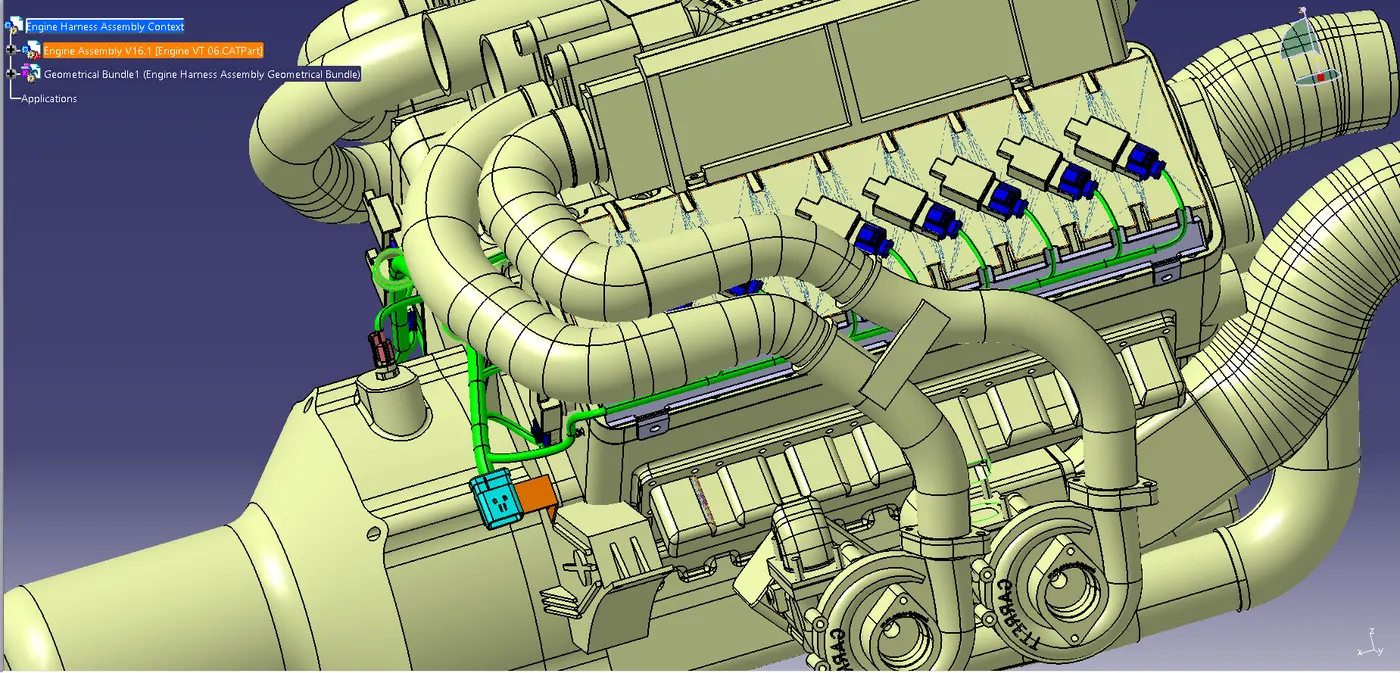
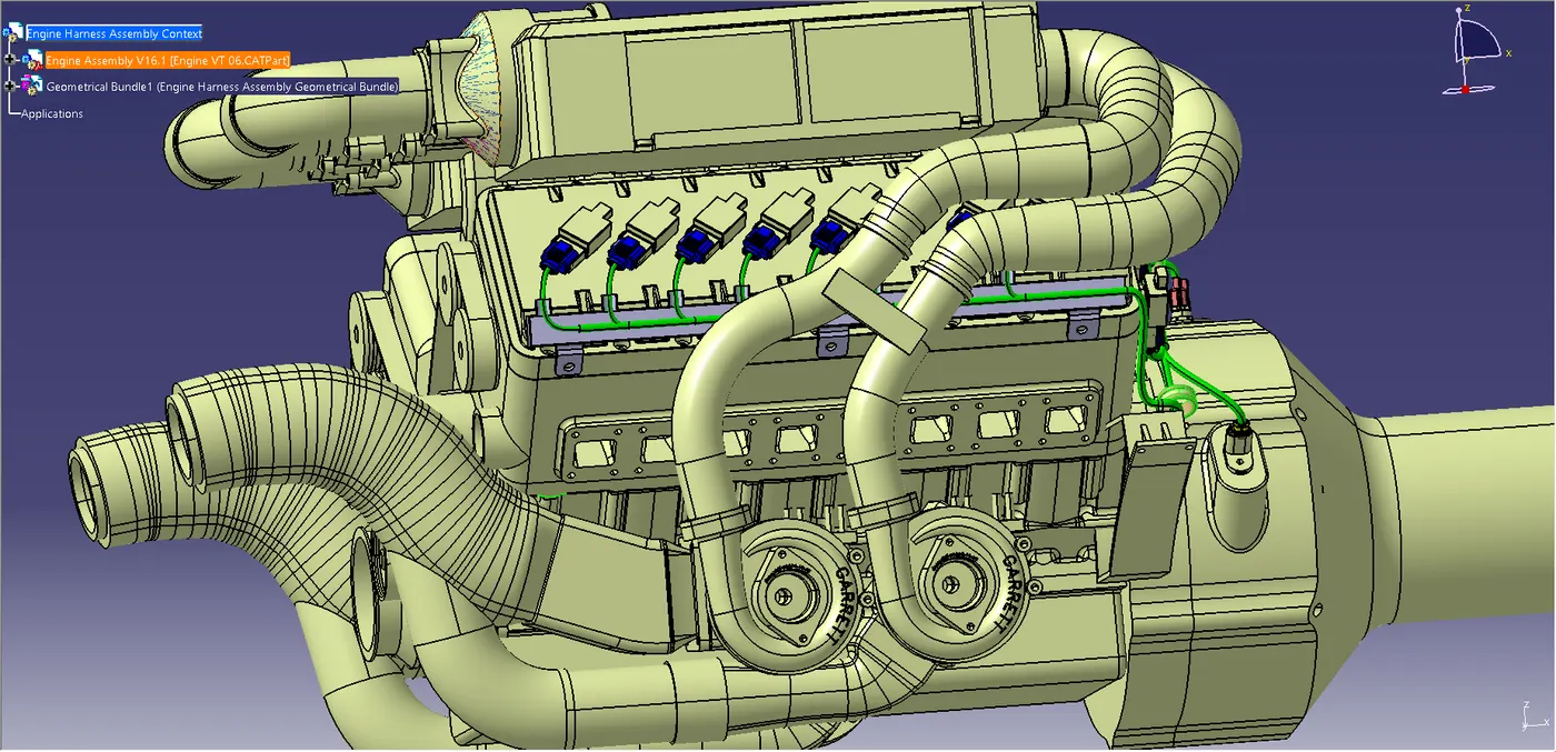
- To Route the wire for the fuel injectors we need to provide a channel so that the wire bundle can be safely routed inside the channel and the wires not get damaged due to the high temperature.
- And Also,the wire bundle can be packaged with proper orientation inside it.
- The channel should be added to the geometric bundle part as it will be a part of the geometrical bundle.
- Also,the Channel should be electrically defined bundle connection point.
- An external curve can be used for routing the wire inside the channel to make it easier for the wire routing.
Step-7:
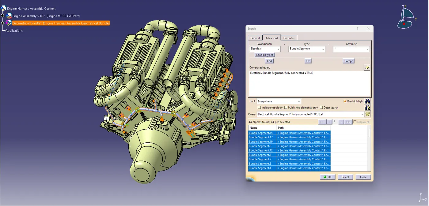
- After completing the routing,we need to check that if any of the bundles is interacting with the engine part.
- There must be proper clearence between the wire bundle and the engine part.
- Additional slack or Fir tree can be placed to ensure proper routing.
- We need to ensure that the entire bundle is fully connected.
Step-8:
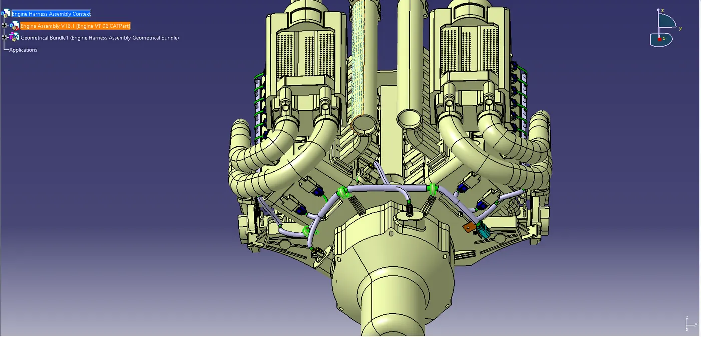
After finally completing the wire harness routing by following the packaging rules we need to provide protection parts wherever necessary.
Applying Protection Part To The Requried Bundles:
Step-9:
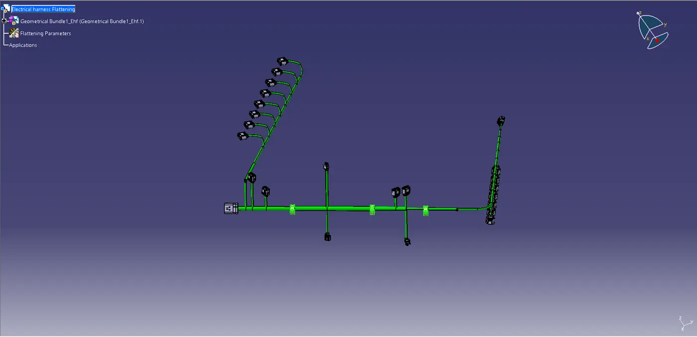
- After finally completing the wire harness routing by following the packaging rules we need to flatten our wire harness assembly.
- To create the wire harness flattening we need to create another product file and navigate to the 'Electrical Harness Flattening'workbench.
- In the workbench first we need to define the Harness Flattening parameters and then extract the geometrical bundle from the wiring harness context product file.
- Then we can select all the branches and flatten the entire geomtrical bundle.
- If all the bundles are fully connected then by selecting 'Select all branches',the entire bundles can be selected and flattened.
- The bundles can be rotated and rolled with a proper radius in order to fit the drawing sheet.
Wiring Harness Flattening:
Step-10:
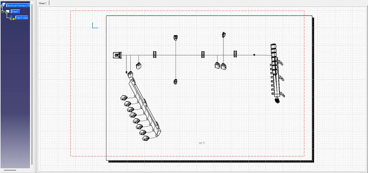
After the wire bundle is flattened in the respective product file and workbench it can be represented in the drawing sheet.
Conclusion:
From the above project we learnt how to route wire harness on a V16 Engine,and we also learnt about different packaging rules that must be kept in mind during wire routing.We also learnt how to flatten the wire and represent it in the drawing sheet.
https://drive.google.com/file/d/1jRkyE1r2nBV-wPyDeuVynf1FN6gPE47B/view?usp=sharing