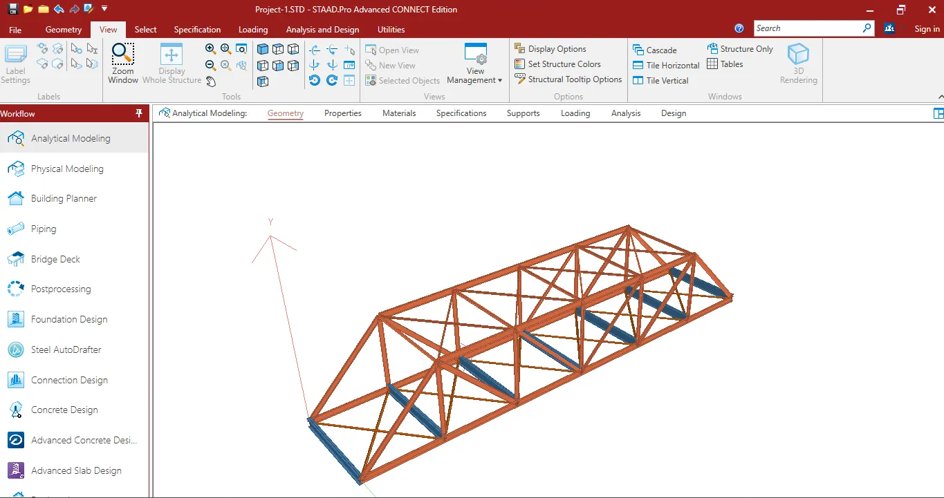
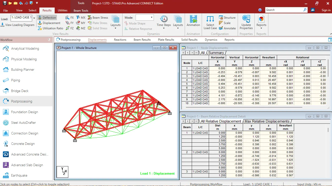
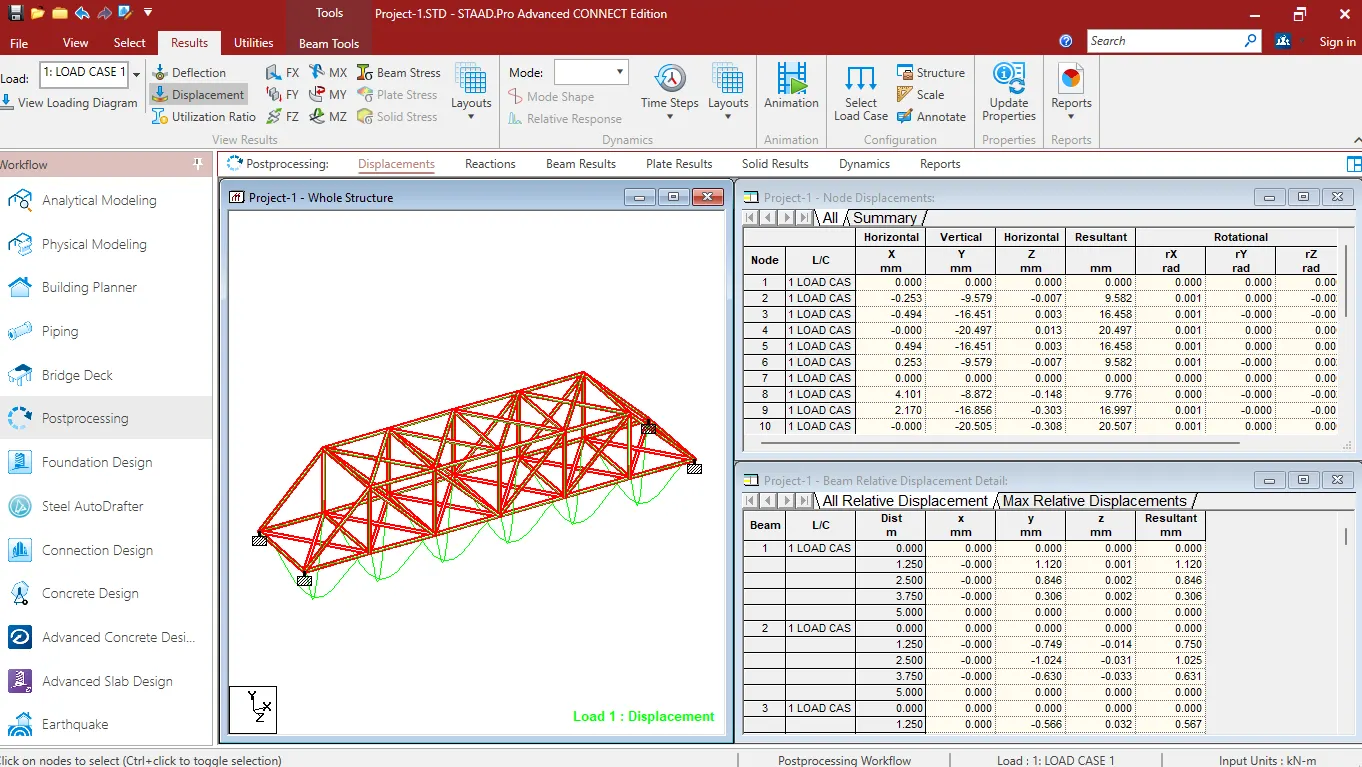
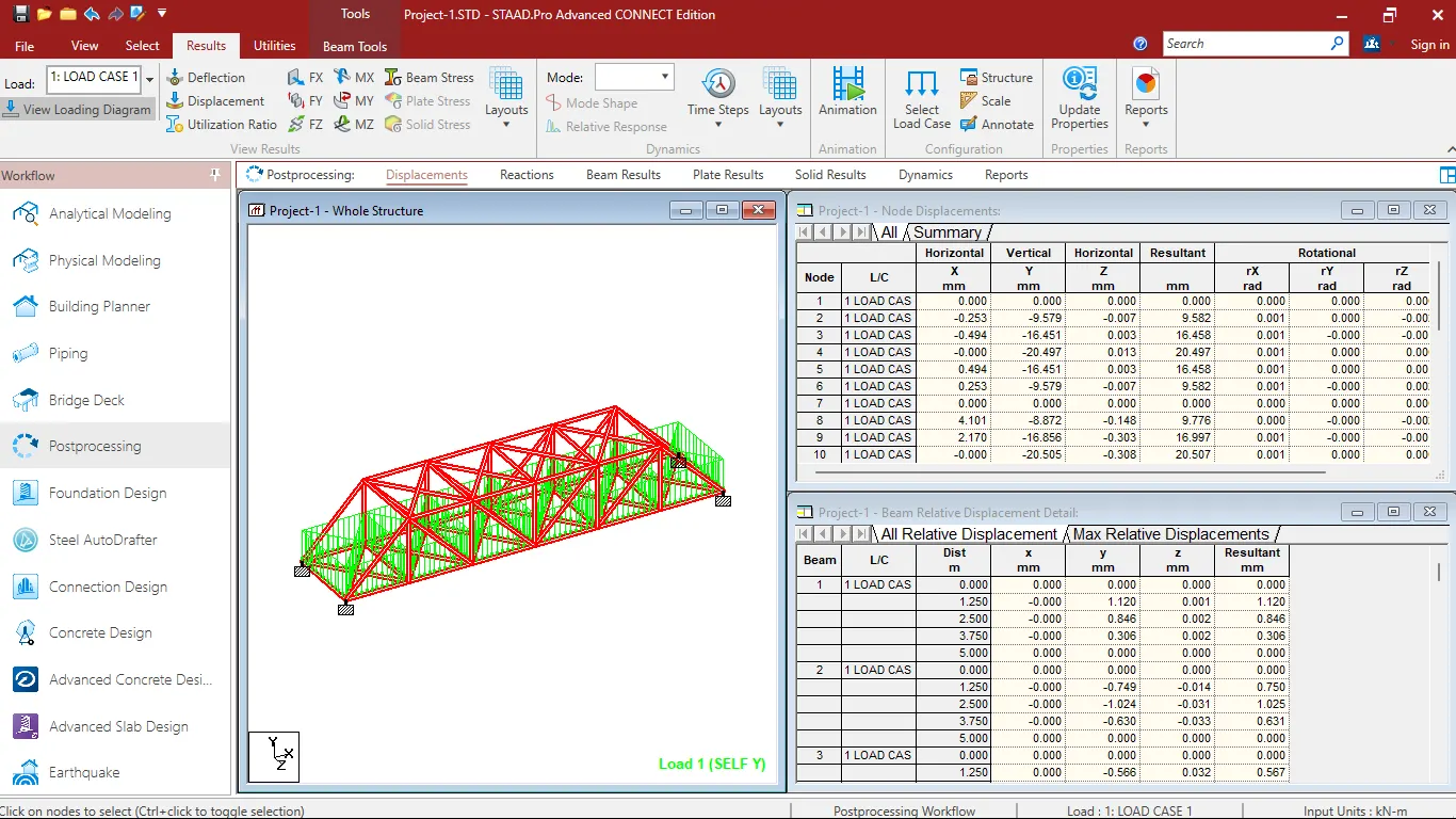
Project 1
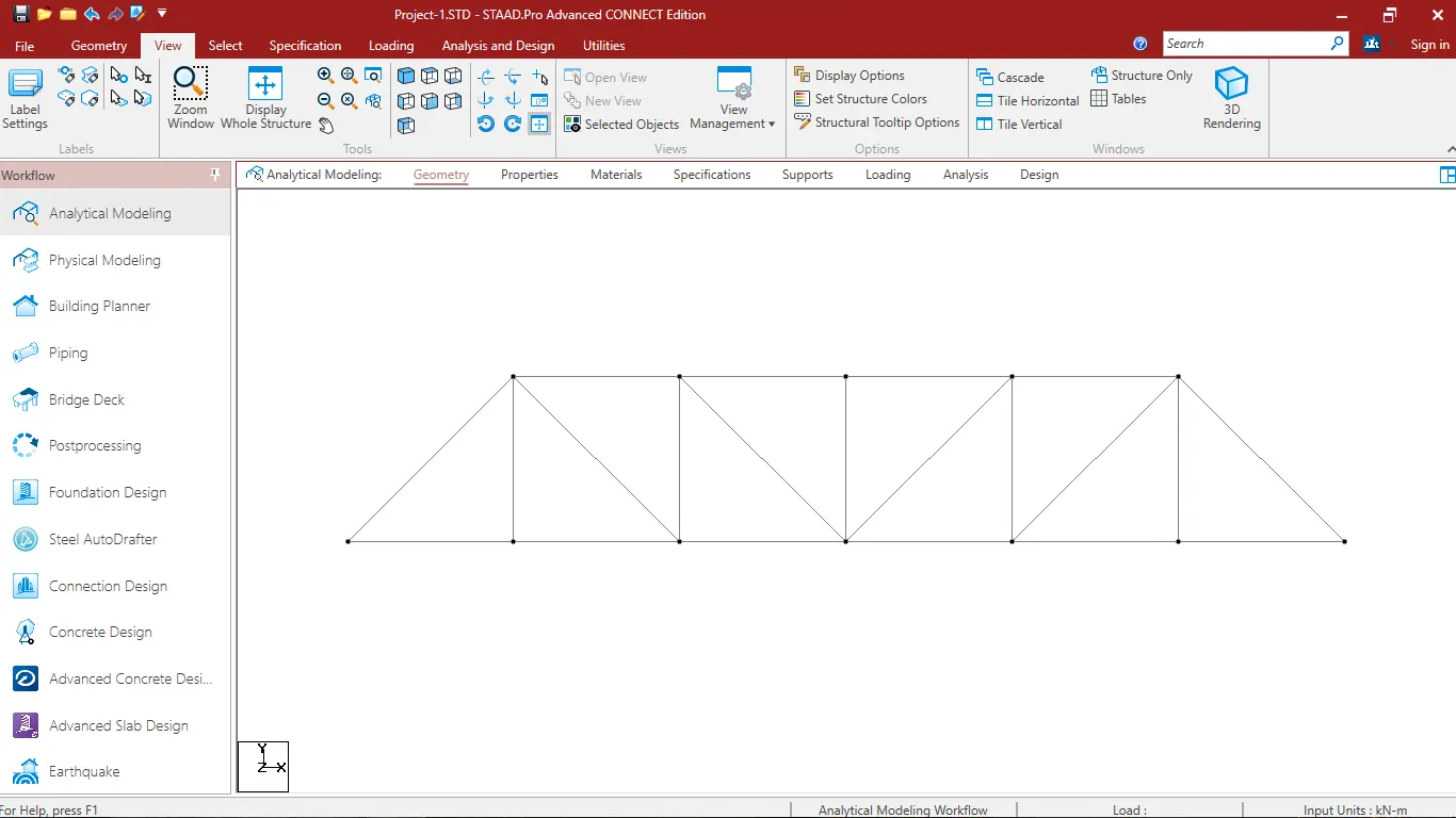
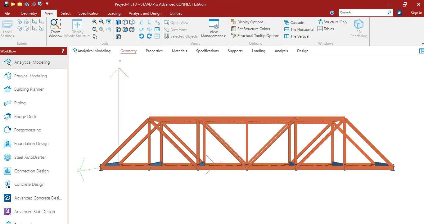
To perform the structural analysis and design of a steel truss bridge, we will follow a step-by-step approach.
Step 1: Bridge Geometry and Loading
We need to define the geometry of the bridge, including the span length, truss type, and member dimensions. For the loading, we'll consider:
-
Dead Load (DL): The self-weight of the truss members, deck, and other permanent components.
-
Live Load (LL): The live load includes the weight of vehicles, pedestrians, and other transient loads. we mentioned the railing load of 7.5 kN/m, which is a part of the live load.
-
Wind Load (WL): Wind load depends on the location and local wind codes. we will need to determine the appropriate wind load for our region.
-
Other Loads: Consider any other loads like snow load, seismic load, etc., depending on the site conditions.
Step 2: Load Combinations
Load combinations are created to consider the most critical loading scenarios. Common combinations include DL + LL, DL + WL, and DL + LL + WL. The load factors for these combinations depend on local codes and design criteria.
Step 3: Truss Analysis
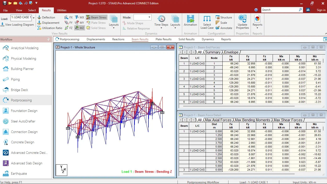
Use a structural analysis software or manual calculations to analyze the truss for each load combination. This will give us the critical forces (axial, shear, and moment) in each truss member.
Step 4: Member Sizing and Section Check
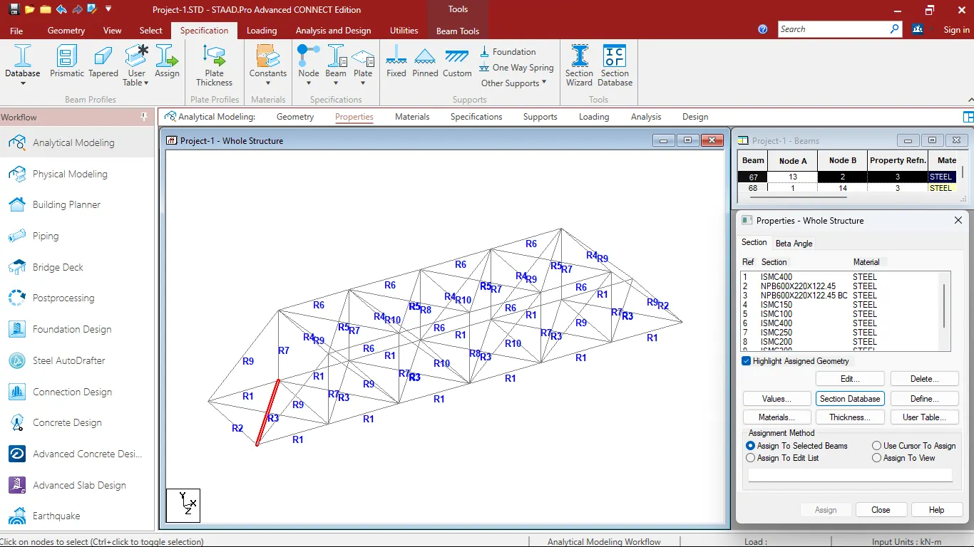
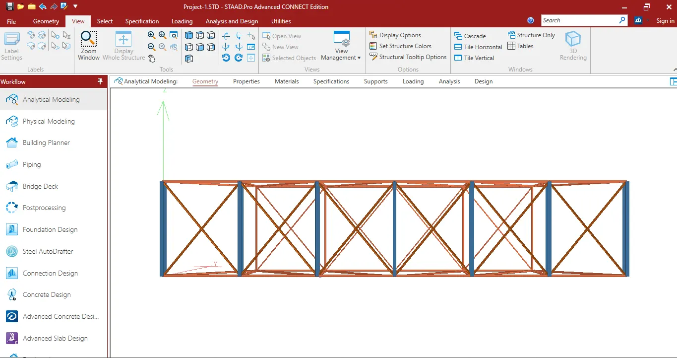
For each member (bottom chord, vertical members, diagonal members, cross girders, top chord, stringers), We'll need to determine the required section size (e.g., I-beams) based on the critical forces and the material properties (yield strength) of the steel we plan to use. Use structural design codes (e.g., IS 800 to select appropriate sections.
If the selected sections are insufficient, we will need to increase their size until they meet the required capacity. This may require iterative calculations.
Step 5: Self-Weight Calculation
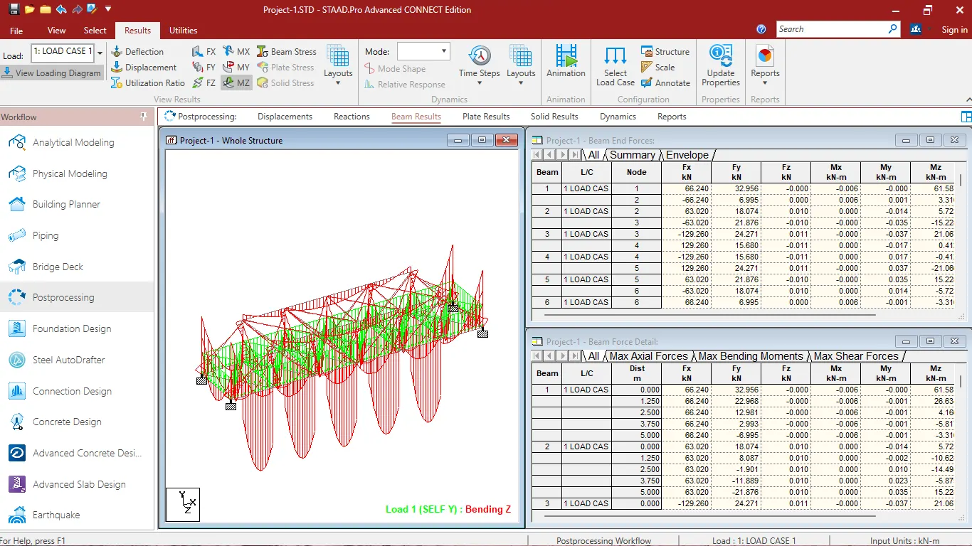
Calculate the self-weight of the truss structure, including all the members, connections, and additional components like the deck.
Step 6: Connection Design
For the splice plate connection in the top chord, we will need to calculate the required number and size of bolts (M20) based on the applied loads and bearing capacity of the plates. Ensure that the connection complies with the Indian Codes for structural steel design.
Step 7: Final Check and Documentation
Recheck the entire design to ensure that all members and connections meet safety and code requirements. Document our design calculations, load combinations, member sizes, and connection details for future reference and for submission to authorities if required.
Calculation of Self Weight:
To calculate the self-weight of the truss, we need to determine the weight of each individual member in the truss and then sum up these weights. The self-weight of each member is equal to its volume multiplied by the density of the material (steel) and the acceleration due to gravity (typically 9.81 m/s⊃2;). Procedure to calculate the self-weight of the truss:
-
Determine the lengths of all the truss members. We should have this information from our truss design.
-
Calculate the volume of each truss member based on its cross-sectional area (A) and length (L). The formula for volume (V) is:
V = A × L
-
Determine the density of the steel material we are using. The density of steel is typically around 7850 kg/m⊃3;.
-
Calculate the self-weight (W_member) of each truss member using the formula:
W_member = V × Density × Gravity
Where:
- W_member is the self-weight of the member (in Newtons or N).
- V is the volume of the member (in cubic meters or m⊃3;).
- Density is the density of steel (in kg/m⊃3;).
- Gravity is the acceleration due to gravity (approximately 9.81 m/s⊃2;).
-
Sum up the self-weights of all the truss members to find the total self-weight of the truss.
Let's assume we have two truss members:
- Member 1: Length (L1) = 5 meters, Cross-sectional area (A1) = 0.01 m⊃2;
- Member 2: Length (L2) = 7 meters, Cross-sectional area (A2) = 0.015 m⊃2;
Density of steel (Density) = 7850 kg/m⊃3; Acceleration due to gravity (Gravity) = 9.81 m/s⊃2;
Calculations:
For Member 1:
- V1 = A1 × L1 = 0.01 m⊃2; × 5 m = 0.05 m⊃3;
- W1 = V1 × Density × Gravity = 0.05 m⊃3; × 7850 kg/m⊃3; × 9.81 m/s⊃2; = 3837.675 N
For Member 2:
- V2 = A2 × L2 = 0.015 m⊃2; × 7 m = 0.105 m⊃3;
- W2 = V2 × Density × Gravity = 0.105 m⊃3; × 7850 kg/m⊃3; × 9.81 m/s⊃2; = 8252.0675 N
Total Self-Weight of the Truss:
- Total Weight = W1 + W2 = 3837.675 N + 8252.0675 N = 12089.7425 N
So, the total self-weight of the truss in this example is approximately 12,089.74 Newtons (N).
Step 1: Identify the Most Critical Connection
From our structural analysis, determine which connection in the top chord experiences the highest forces. This is typically the connection that requires the most bolts.
Step 2: Calculate the Force in the Top Chord Member
Let's assume the most critical connection has an axial force of 100 kN (compression) in the top chord member.
Step 3: Calculate the Number of Bolts Required
To calculate the number of M20 bolts required, we need to consider the bearing capacity of the splice plate and the bolt.
Bearing Capacity of the Splice Plate (P_plate)
The bearing capacity of the splice plate depends on the thickness of the plate, the diameter of the bolts, and the material properties. Let's assume the plate is 10 mm thick, and the bearing capacity (P_plate) is 200 N/mm⊃2;.
P_plate = (Plate Thickness) x (Plate Width) x (Plate Material's Bearing Capacity)
P_plate = (10 mm) x (Width of the splice plate) x (200 N/mm⊃2;)
Bearing Capacity of the Bolt (P_bolt)
The bearing capacity of an M20 bolt can be determined from the material properties. Let's assume the bearing capacity of an M20 bolt is 100 kN.
P_bolt = 100 kN
Number of Bolts Required (N_bolts)
N_bolts can be calculated using the following formula:
N_bolts = (Force in Top Chord Member) / (Minimum of P_plate and P_bolt)
N_bolts = (100,000 N) / (Minimum of 200 N/mm⊃2; and 100,000 N)
N_bolts = 500 Nos.
So, we would need a minimum of 500 M20 bolts for this splice connection to safely carry the axial force of 100 kN.