Project 1
To solve these structural analysis problems, we will use basic principles of structural mechanics:
Given information:
- Portal beam length: 4m
- Portal beam cross-section: 300mm x 600mm (depth)
- Portal columns height: 3m
- Portal column cross-section: 300mm x 300mm
- Load at each bearing: 75 kN
- Bearing locations: 1m from either end
First, let's calculate the reactions at the supports:
- Total load = 2 * 75 kN = 150 kN
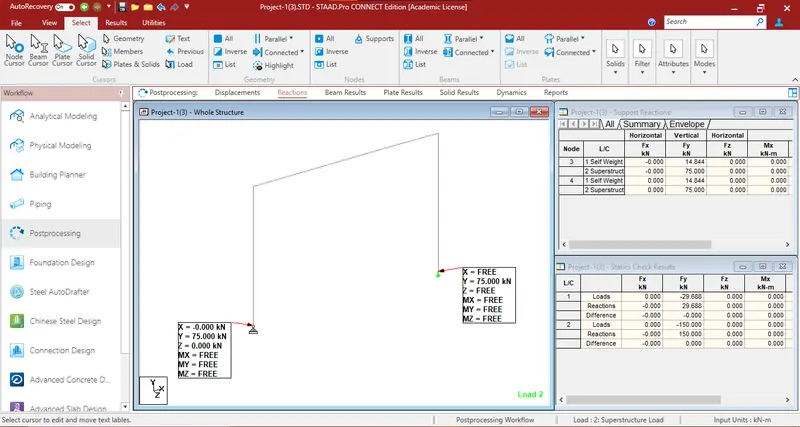
- Reactions at each support = Total load / 2 = 150 kN / 2 = 75 kN
1) The portal beam has two Bearing locations 1m from either end. The load from each bearing is 75 kN. Calculate the support reactions and displacement of each node.
For displacement calculation, we can consider a simply supported beam with a uniformly distributed load. The displacement at the midpoint of the beam can be calculated using the formula for the deflection of a simply supported beam under a uniform load:
δ=5wL^4 / 384EI
Where:
- w = Load per unit length (load at each bearing divided by beam length)
- L = Beam length
- E = Modulus of elasticity of the material
- I = Moment of inertia of the beam cross-section
Assuming steel with a modulus of elasticity E=200GPa and calculating the moment of inertia I for the beam cross-section, we can then calculate the displacement.
- The aim of this challenge is to determine the forces, Bending moment and shear forces acting on the structure with different types of support and different load conditions using Staad Pro.
- So first of all the model will be created in Staad pro. as per the given data with given loads applied on the structure.
- Then create as per different support conditions with different orientations. The reactions, stresses and bending moments due to the loading is being analyzed for different structures and comparing the results with each other.
The portal beam has a length of 4m and a cross-section of 300mm x 600mm (depth) and portal columns have a height of 3m and a cross-section of 300mm x 300mm.
Staad Model
Creating the Project
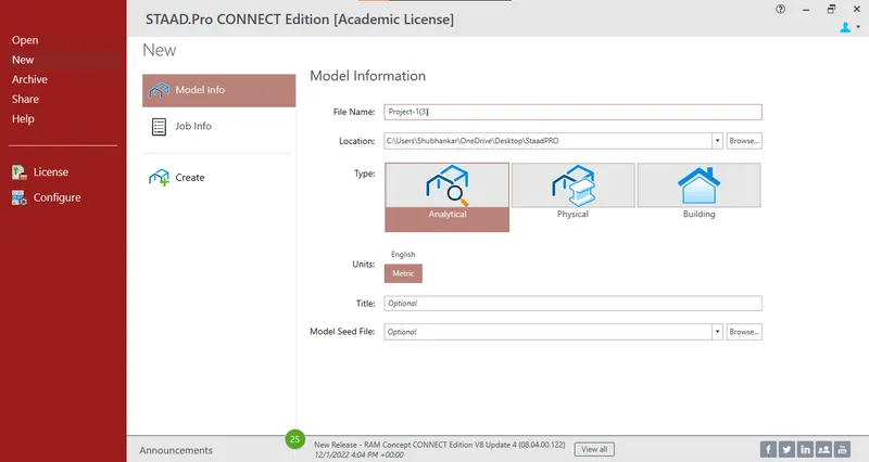
- The portal beam has been created as given with 4m length.
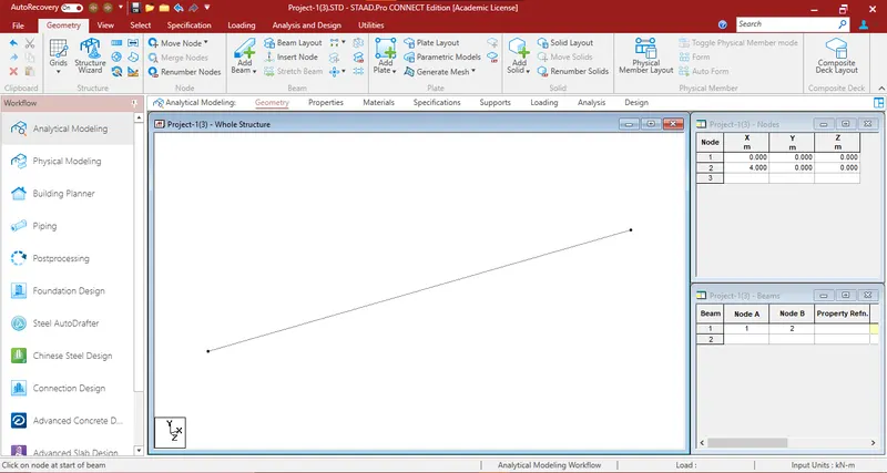
- The columns are also created as given with 3m height.
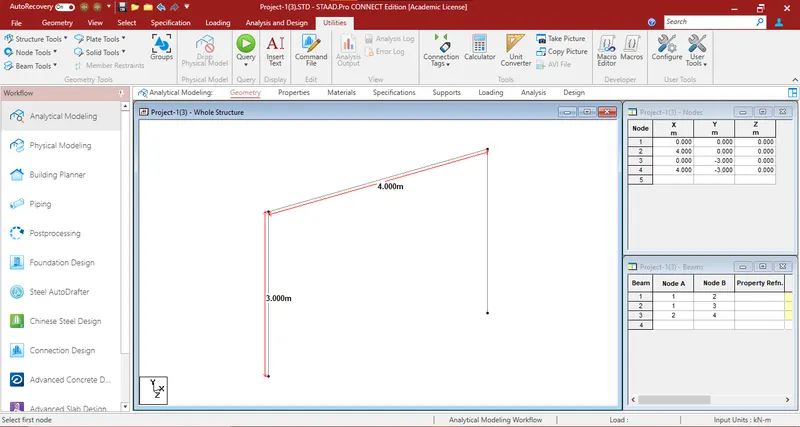
- Two bearing locations have been created.
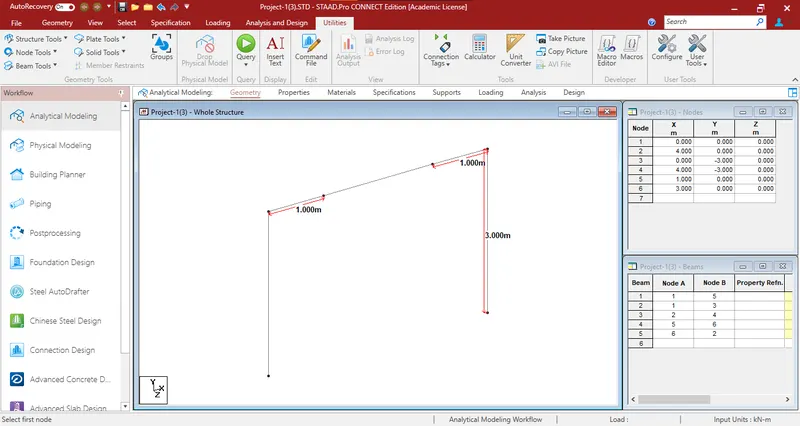
- Property for the beam was defined and assigned to the beam.
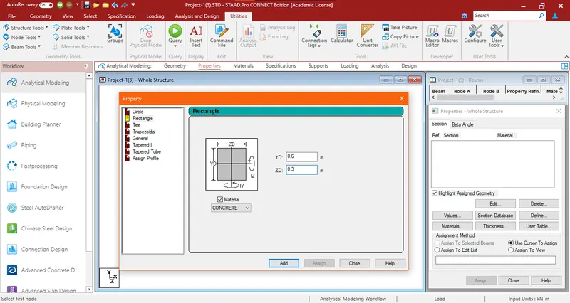
- Property for the columns was also defined and assigned to the columns of the structure.
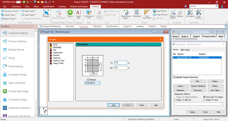
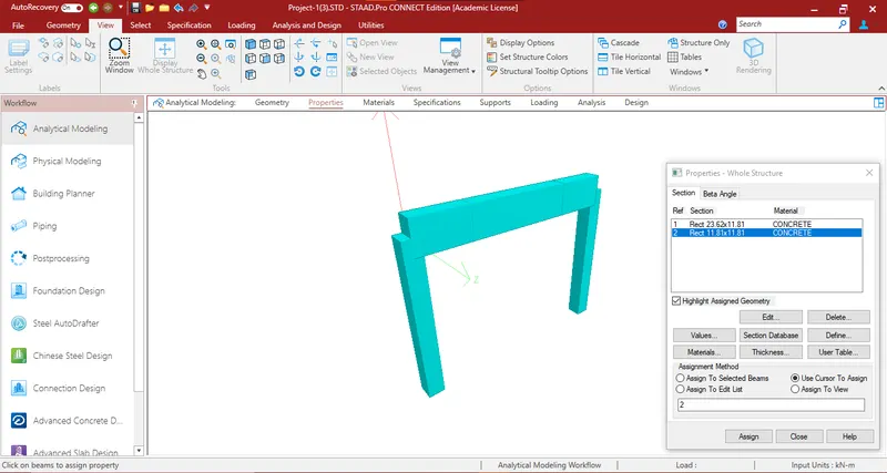
- The 3D view of the portal frame is shown below:
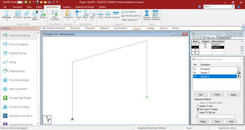
- Support Condition
- Pinned support and roller support have been defined and assigned to either base node.
- Loads and Definitions
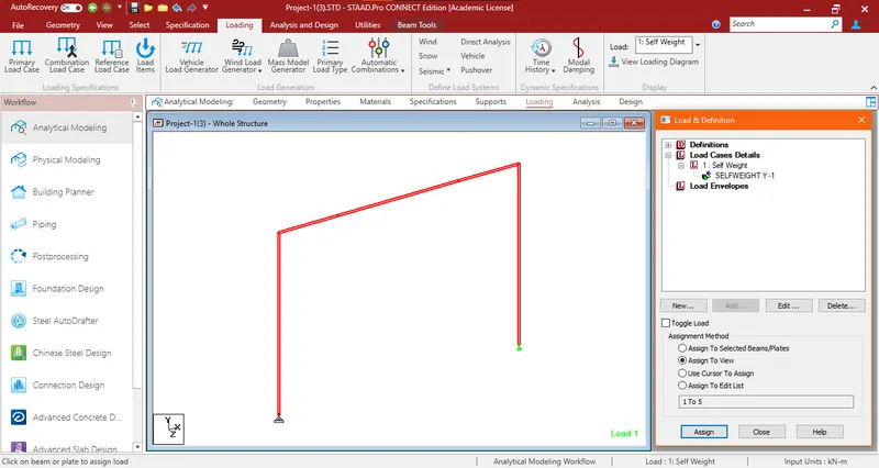
- Dead load defined and was assigned to the whole structure.
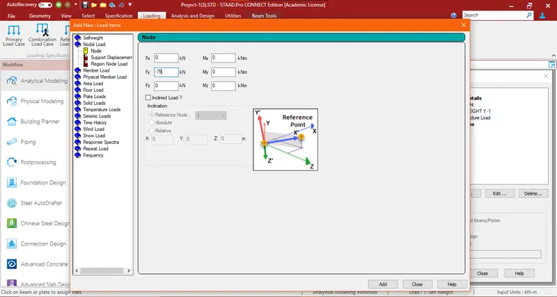
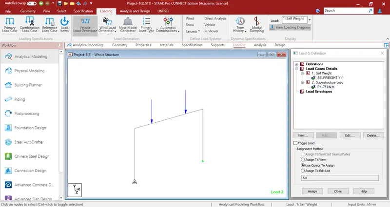
- Superstructure load as nodal load through the bearing was defined and applied to the structure.
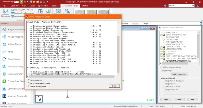
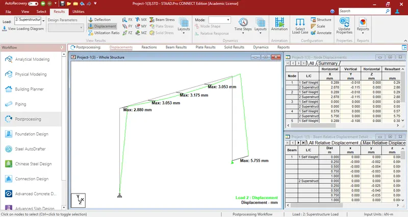
- The structure was analyzed and the output gave the result of 0 error.
Result
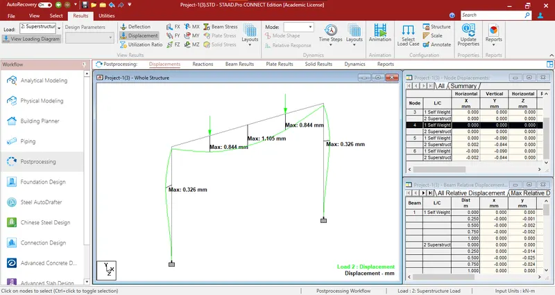
- Displacement
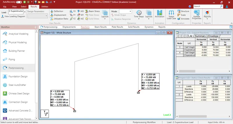
- Support Reaction
2) Now change both the supports to fixed and compare the reactions and displacements with that of the previous sub-question.
Changing the supports to fixed means that the beam is fully restrained at both ends. This will significantly affect the reactions and displacements. The reactions will change, and the displacement at the midpoint will be reduced compared to the simply supported case.
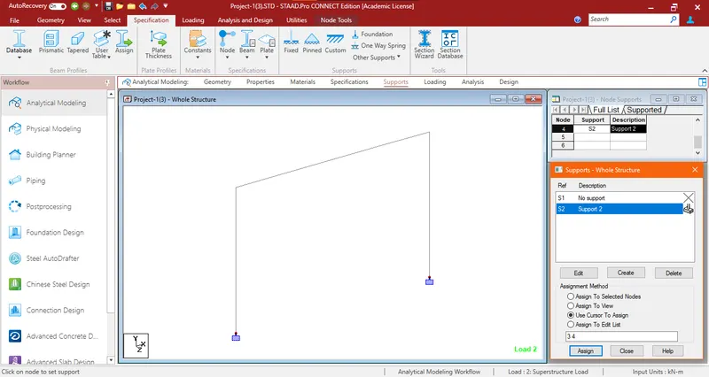
- In this case, the support conditions were changed to fixed support on both nodes.
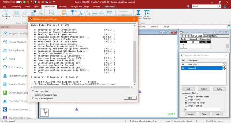
- The structure was analyzed and the output gave the result as 0 error.
-
Result
- Displacement
- For the maximum load case
- Support Reaction
3) Now provide 3 support conditions with 50 kN such that the total load on the frame is the same as that of Point 1. The bearings are 1m apart and 1st bearing is 1m from the end. Compare the reactions with that of sub-question 2 and comment on the results.
- Created the third support node from the superstructure in the mid-section of the beam.
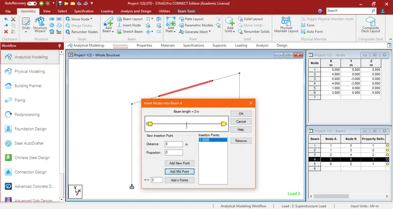
- 3 support conditions for bearing were created and 50 KN was applied to the structure.
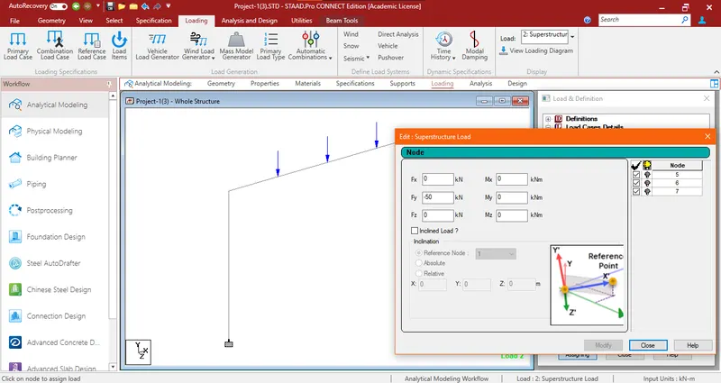
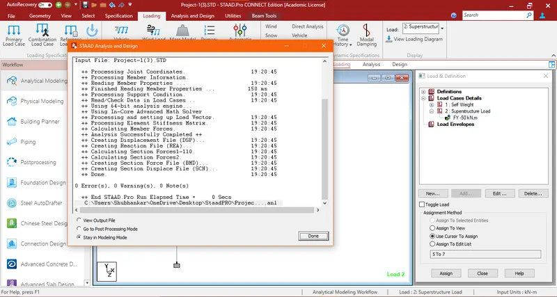
- The structure was analyzed and the output gave the result of 0 error.
-
Result
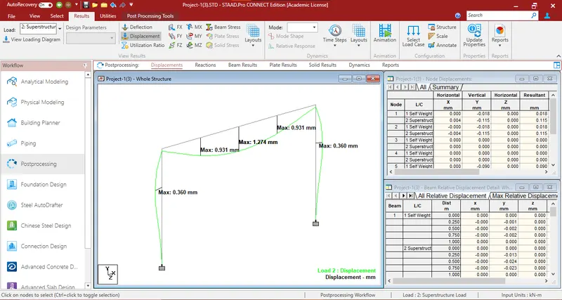
- Displacement
For the maximum load case
- Support Reaction
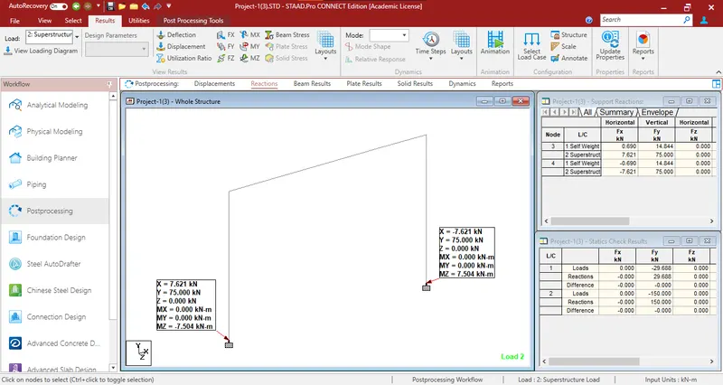
- In this case, after comparing to Case 2, the displacement in the midpoint was found to be higher in this case (Case 3).
- But as the superstructure loading is symmetrical in both cases and the magnitude is the same, the vertical reaction (Y =75 kN) in both cases is the same.
4) Change the cross-section of the column to 300 x 400 mm such that the 300mm width of the column aligns with the 300mm width of the Portal beam. Rest all conditions remain the same as that of sub-question 2. Compare the portal beam and columns bending moment with that of sub-question 2.
Changing the column's cross-section to 300mm x 400mm while aligning the 300mm width with the portal beam's width would affect the column's moment of inertia. A larger moment of inertia would lead to lower bending moments in the column. This change could potentially reduce the bending moments in the beam as well. The exact calculations would depend on the specific loading conditions and the material properties.
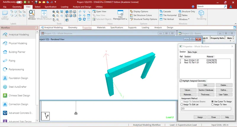
- The cross-section of the column was changed to 300 x 400 mm in the model with reference to Case 2.
- The property in the model was changed.
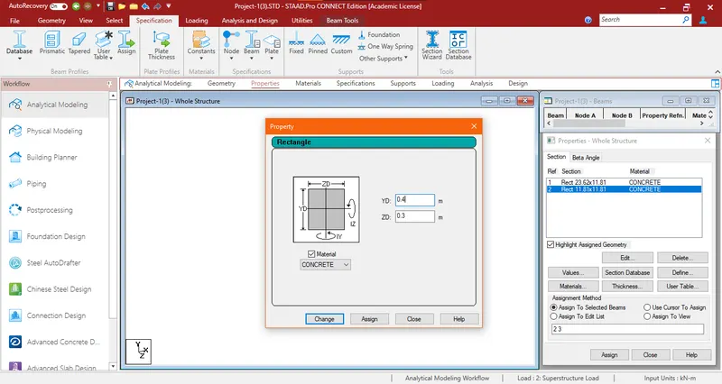
- The 3D view of the structure after aligning the 300mm width of the column section to the 300mm of the beam section is shown below:
- All other sections, loadings & support conditions remained the same.
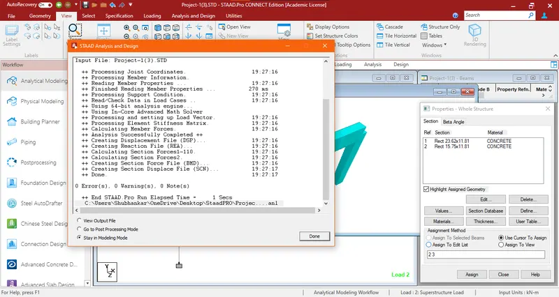
- The structure was analyzed and the output gave the result of 0 error.
Result and Comparision
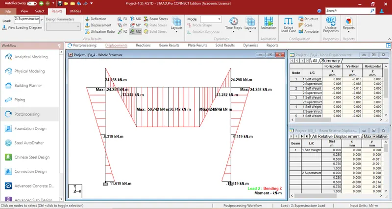
- The Bending Moment Diagram with Maximum Magnitude and Magnitude at Mid Point and Ends for the model created in Case 4 is shown below:
- The Bending Moment Diagram with Maximum Magnitude and Magnitude at Mid Point and Ends for the model created in Case 2 is shown below:
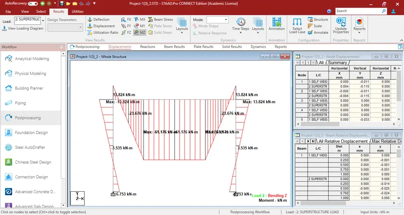
From the above two results, it can be concluded that the Bending Moment at the Mid Section of the Beam is more in Case 2 as compared to Case 4.
The bending moment in the midsection of the beam is lesser in Case 4 but the end moment is higher as the section (YD) in this case was increased.
5) Now change the orientation of the column such that the 400mm size aligns with the 300mm width of the Portal beam. Compare the beam and column results with that of Sub-question 4. Comment on the results.
Changing the orientation of the column so that the 400mm size aligns with the 300mm width of the portal beam could affect the stability of the structure. The 400mm dimension would not provide as much resistance against lateral buckling compared to the 300mm dimension. This might result in reduced overall stiffness and increased lateral deflections in the structure.
- The cross-section of the column was changed to 400 x 300 mm from 300 x 400mm in the model with reference to Case 4.
- The property in the model was changed accordingly.
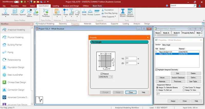
- The 3D view of the structure upon aligning the 400mm width of the column section to the 300mm of the beam section is shown below:
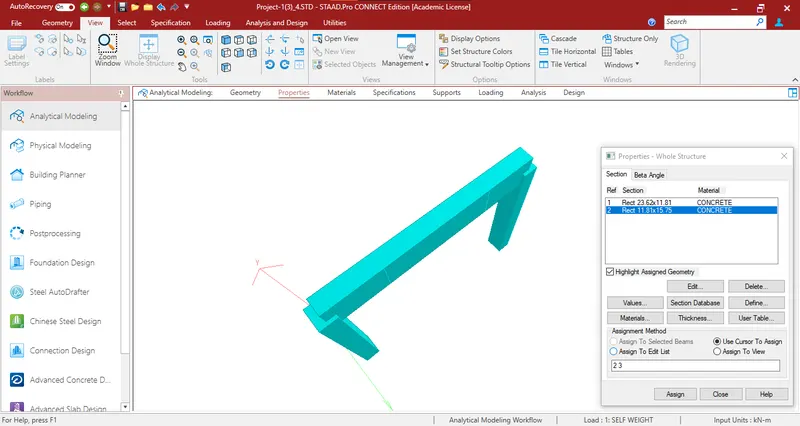
- All other sections, loadings, & support conditions remained the same.
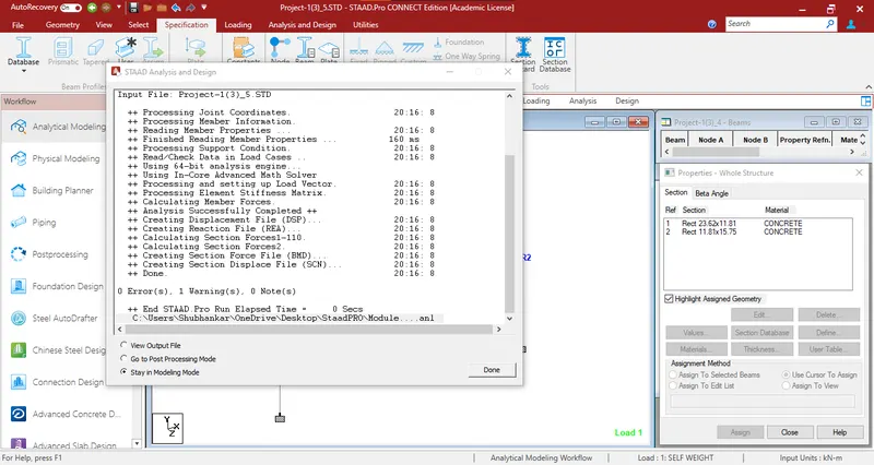
- The structure was analyzed and the output gave the result of 0 error.
Result and Comparision
- The Bending Moment Diagram with Maximum Magnitude and Magnitude at Mid Point and Ends for the model created in Case 4 is shown below:
- The Bending Moment Diagram with Maximum Magnitude and Magnitude at Mid Point and Ends for the model created in Case 5 are shown below:
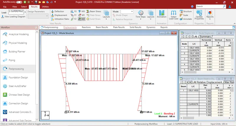
- The Bending Moment in the Mid Section of the Beam is higher and the Bending Moment in the end section in Case 5 is lesser as compared to Case 4. This is because the section modulus in the respective 400mm dimension direction is higher than in the other direction.
- Shear Force
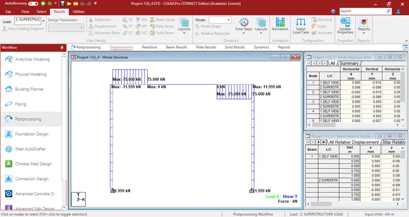
- The shear force with Maximum Magnitude and Magnitude at the Ends for the model created in Case 4 is shown below:
- The shear force with Maximum Magnitude and Magnitude at the Ends for the model created in Case 5 is shown below:
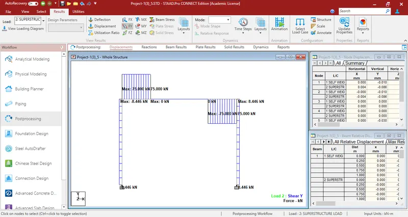
The Maximum Shear in the columns is greater in Case 4 as compared to Case 5 which is due to the change in width of the column.
Axial Force
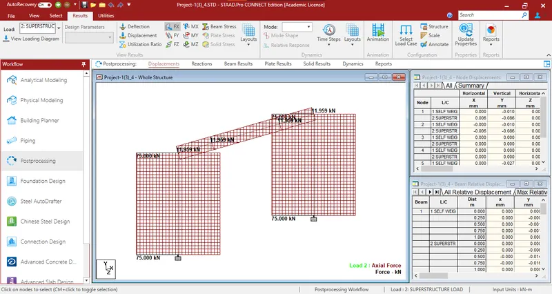
- The Axial Force for the model created in Case 4 is shown below:
- The Axial Force for the model created in Case 5 is shown below:
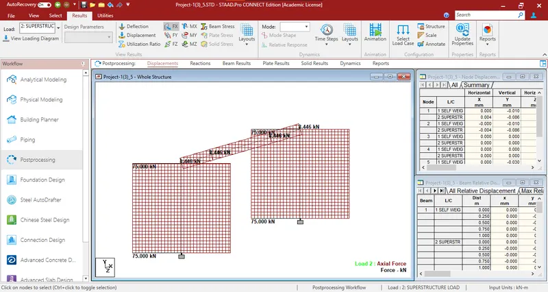
In this comparison, axial force in the Beam in Case 4 is greater as compared to Case 5 which is due to the change in the width of the column.
General comments based on the information provided in the sub-questions:
1) In this case, with simply supported conditions, the portal beam experiences bending due to the applied loads. The reactions are evenly distributed between the two supports, and the displacement at the midpoint is relatively larger compared to other support conditions.
2) Changing the supports to fixed significantly increases the stiffness of the structure. This leads to higher reactions at the supports and reduced displacements at the midpoint of the beam. The structure becomes more resistant to deformation and is capable of transmitting larger loads.
3) Since the specific support conditions and their locations are not provided, it's hard to comment on this particular case. However, varying the support conditions can have a significant impact on the overall behaviour of the structure. Some support conditions may result in higher reactions, while others may allow for more flexibility in the structure's response to loads.
4) Changing the column cross-section to 300mm x 400mm, with the larger dimension aligned with the portal beam, could potentially decrease the bending moments in both the beam and the column. The increased moment of inertia of the column's cross-section would lead to better load distribution and reduced overall bending.
5) Orienting the column such that the 400mm dimension aligns with the 300mm width of the portal beam could introduce stability issues. The column might be more prone to buckling in the direction with the smaller dimension. This could result in increased lateral deflections and reduced overall stiffness of the structure.
In all cases, structural analysis involves a trade-off between load-carrying capacity, stiffness, stability, and overall deformation. The specific design decisions depend on the intended use of the structure, safety requirements, and aesthetic considerations.