Project 1
WIRING HARNES PROJECT 1
AIM:
To Route the Wiring harness on Given Engine and Prepare flatten view drawing in CATIA V5. Application of all Packaging rules shall be demonstrated in design. Apply Protection coverings as required and Prepare & Submit all necessary reports like clearance, Clipping/Clamping selection, Harness fixing requirements, Harness continuity, Assumptions if any along with CATIA 3D data.
INTRODUCTION:
A wire harness, also commonly referred to as a wiring harness, is an exterior sheath used to cover some types of electronic wires. Generally, wiring harnesses are made of thermoplastic or thermoset materials that can help protect the cables from the environment.
ENGINE HARNESS:
There are many cables in the engine wiring harness that work to connect electricity to your vehicle parts. This vehicle part has many sensors, and they work to ensure that everything in your vehicle is in working order. Some of these major systems in your car are fuel and transmission. When you get a check engine light, you have the engine wiring harness to thank. It works by using these cables and a fuse box. They wire the electricity produced by the engine to the various parts and sensors. It is created using high-temperature plastic or rubber because the engine heats up a lot. That could cause the engine wiring harness to melt over time. And while this is a rare occurrence, it does happen.
Think of this part of the vehicle like the brain. Without it, it wouldn’t be possible to get the information your vehicle needs. It’s always working overtime to relay the data your vehicle needs to function correctly. Whenever a sensor goes off, it’s because the engine wiring harness alerted the sensor of the problem. The exciting thing is that as vehicles get more advanced, the engine wiring harness grows. Some say that new cars have over 100 pounds of wires, so imagine how many things could go wrong with that. In the past, there may not have been many issues. However, as things advance, there are more to go wrong.
GIVEN ENGINE DATA:
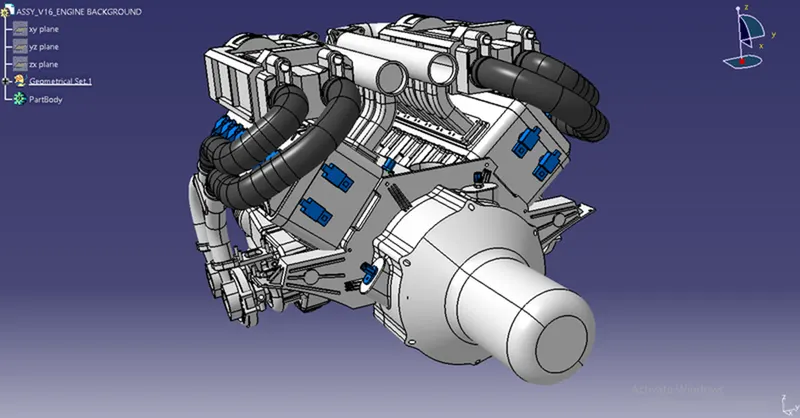
Fuel injector for each cylinder we have 16cylinder engine. Camshaft sensors on each engine block (4 camshaft sensor), Engine coolant sensor at the centre of the engine between the two blocks. Engine oil temperature and oil pressure sensor fitted at the oil sump of the engine on both engine cylinder blocks. Sensors for sense neutral position of the transmission assembly and measure the vehicle speed. Interconnection connector to connect engine harness system to vehicle harness system. Harness mounting and routing management required to provide proper packaging of the wiring harness.it also deals with clearance management and manufacturability. P-clamps to provide positive clamping and proper clearance management for the routing. Mounting clips for connector mounting, guiding channels provide thermal protection in high temperature zones. Corrugated tubes used to protect the wiring harness from hazardous liquids and temperature.
DEFINE CONNECTORS:
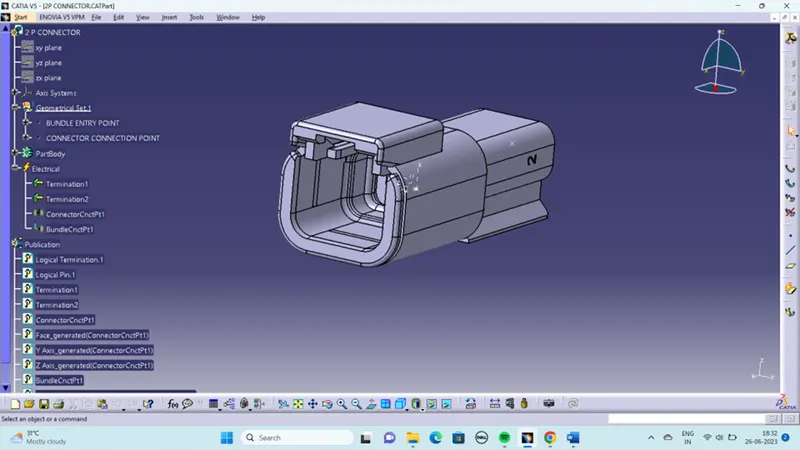
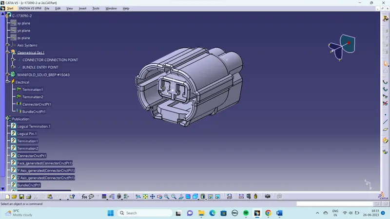
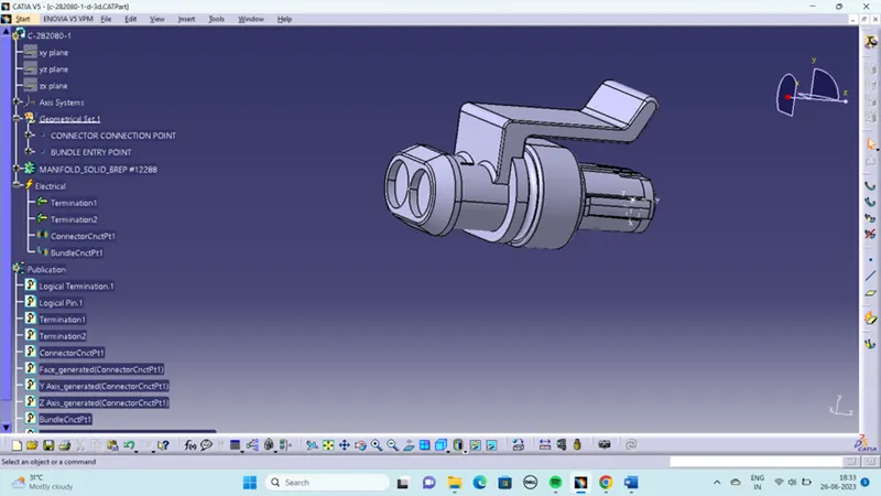
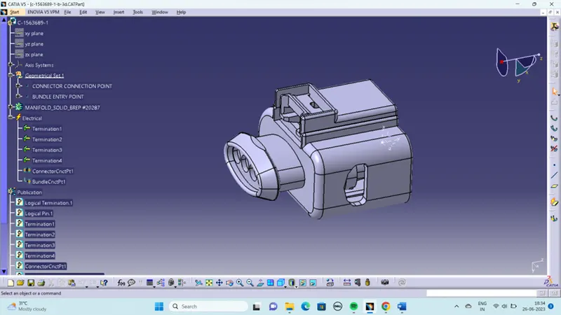
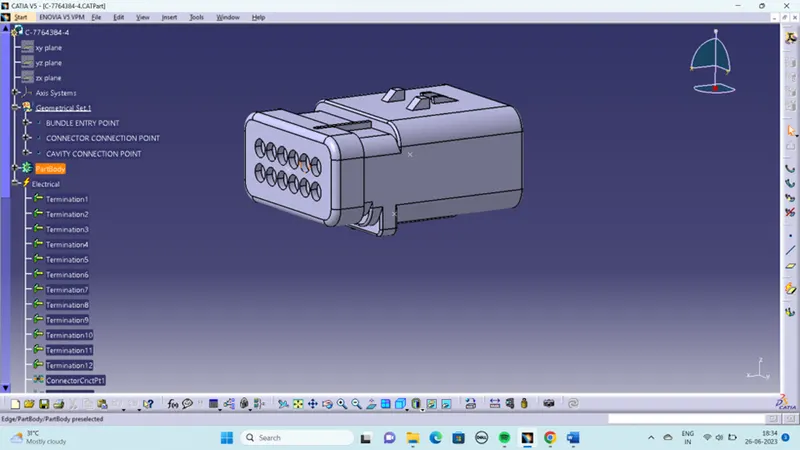
open the cad data of connectors in Catia part design workbench and create the connector connection point, connector connection axis system, bundle connection point. Then Switch to electrical part design workbench and define it as a connector also define connector connection point and bundle connection point. Here we have interconnection connector it requires mounting clip for mounting the connector .so cavity connection point should be defined for this connector. All the connectors defined as electrical connector and defined all the necessary properties to Connectors. Created a catalogue document in connector family and stored all the connector data in catalogue document.
MOUNTING CHANNELS:
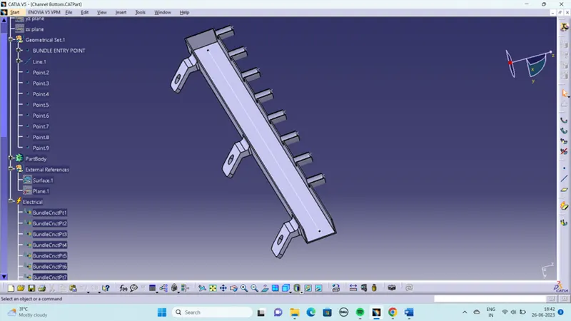
- Procedure for electrically defining the Channel.
- Create bundle entry point and exit point.
- Create a line curve between the main entry and exit points for creating the multi-branchable using external curve inside the channel
- Create 8 bundle entry points on the openings for connecting the injector connectors.
- Using the geometrical parameters, define the channel electrical using the define mounting equipment option.
- Create define bundle entry points using the “define bundle connection point option.”
- Other side create channel symmetrical assembly and define the symmetry bottom channel electrically using define mounting equipment option and also create all the required geometrical parameters on it.
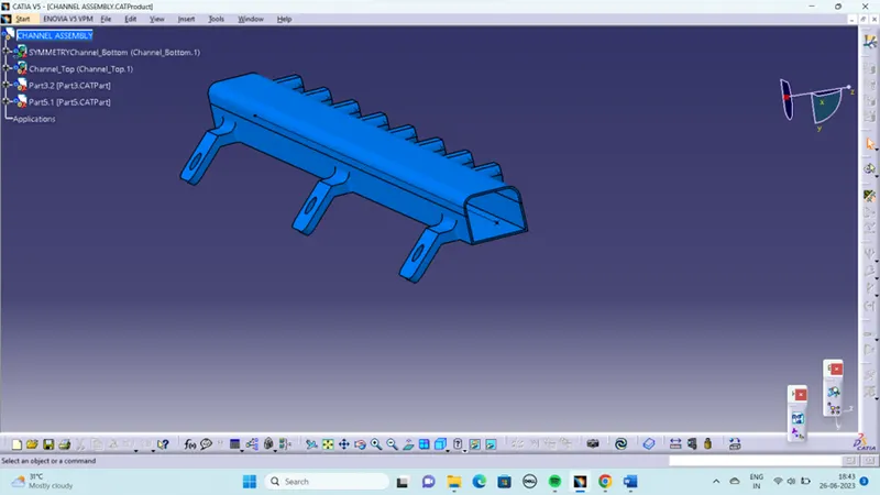
Mounting clips and clamps:
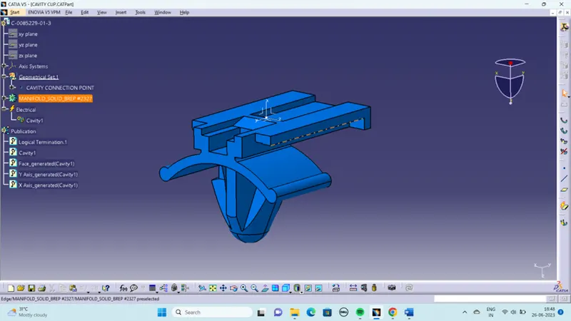
define the mounting clip electrically by defining all the properties. Define the clip as mounting equipment using mounting equipment command. Select cavity command and define the parameters.
CAVITY CLIP:
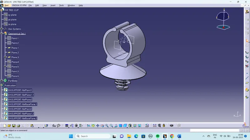
FIR TREE CLIP:
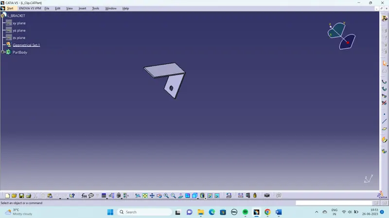
L- BRACKET:
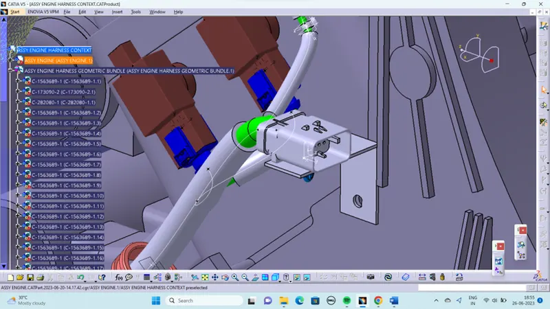
However, situation of interconnection connectors are not similar to device connectors. Interconnection connectors are not parked with any device but should be pared with the help of clips/clamps/sheet metal brackets etc. possible to the packaging conditions.
Un parked connectors can create following issues-
- Rattling noise
- Physical damage to connectors
- Uncontrolled harness routing
- Manual errors during assembly because of undefined parking.
Assume the bundle connection from the chassis is coming from right side of the engine and therefore L-clamp is provided on the right side of the engine which provide proper support for the interconnection connector. Here the cavity clip is inserted into the hole provided on the L-clamp.
Additional slack should be provided to the chassis bundle connecting to the engine harness interconnection connector to protect the wiring harness from vibrations caused during the vehicle operation.
P-CLAMP POSISTIONING:
CONNECTORS:
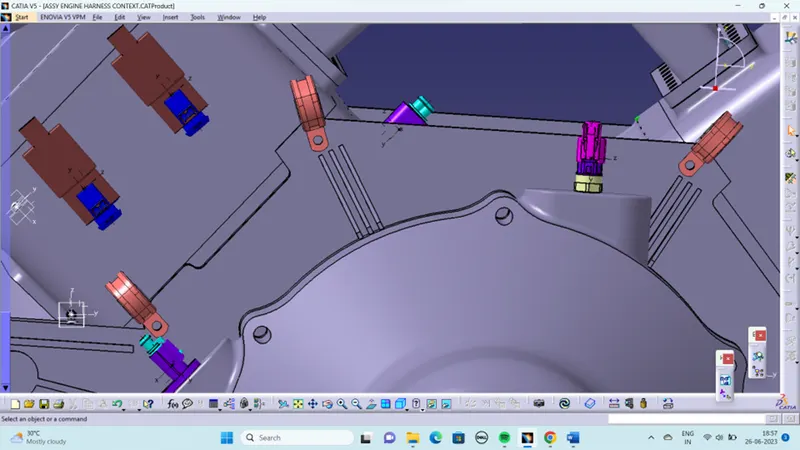
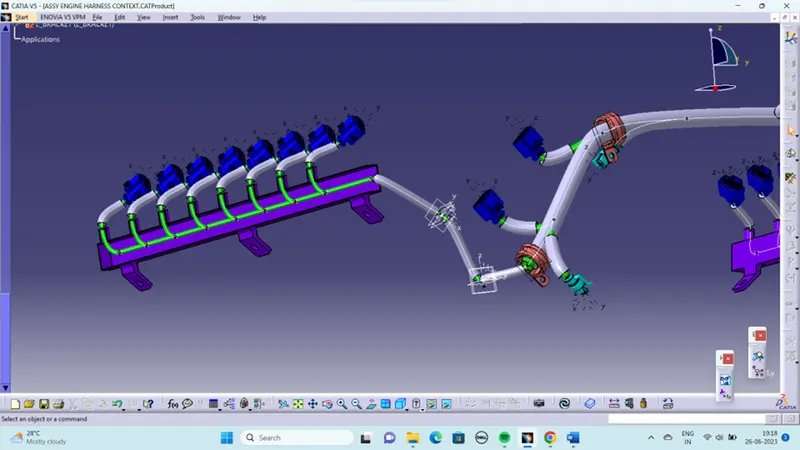
The available connectors are added into the geometrical bundle and properly positioned onto the fuel injectors, camshaft sensors, vehicle speed sensor, neutral position sensor and engine coolant sensor. manipulation tool is used to place the connectors.
PLASTIC CHANNEL POSISTIONING:
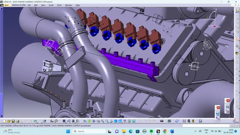
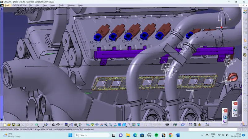
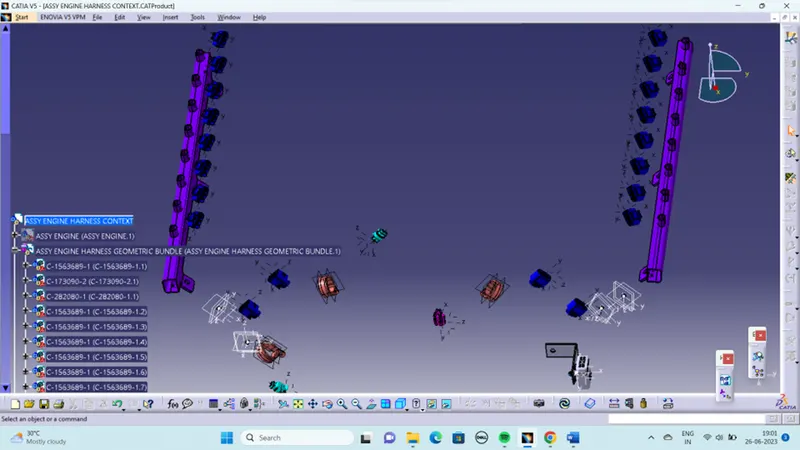
HARNESS ROUTING:
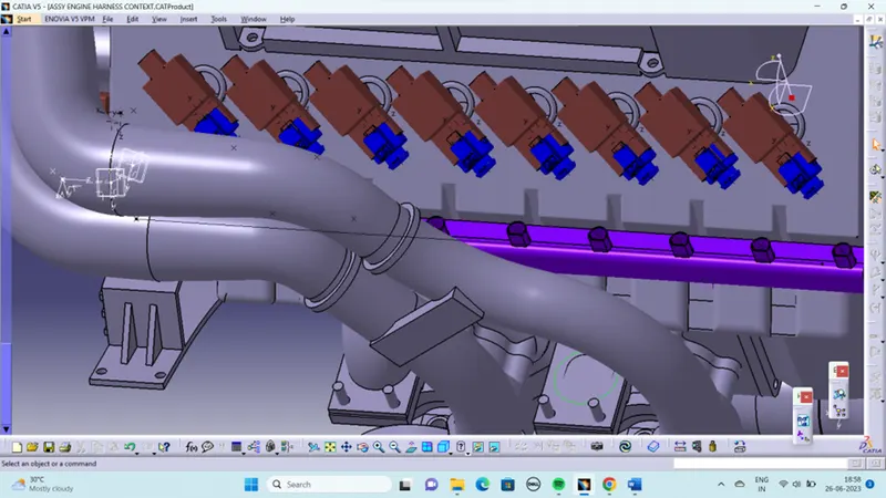
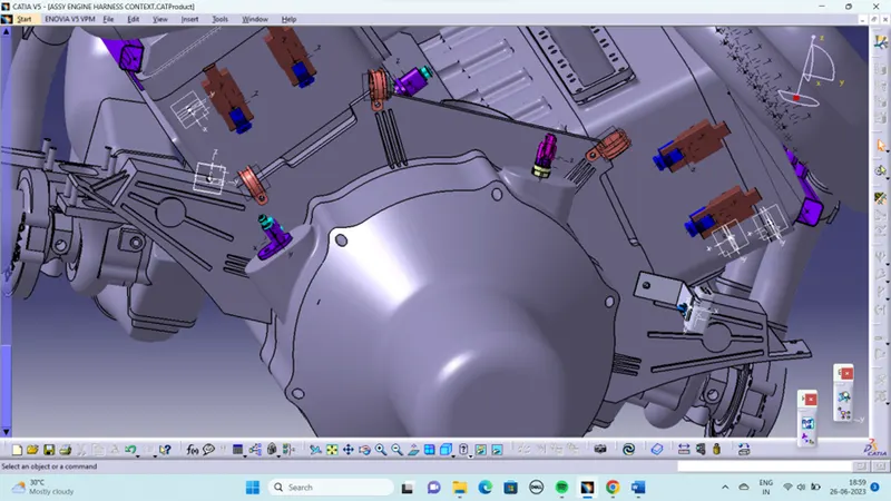
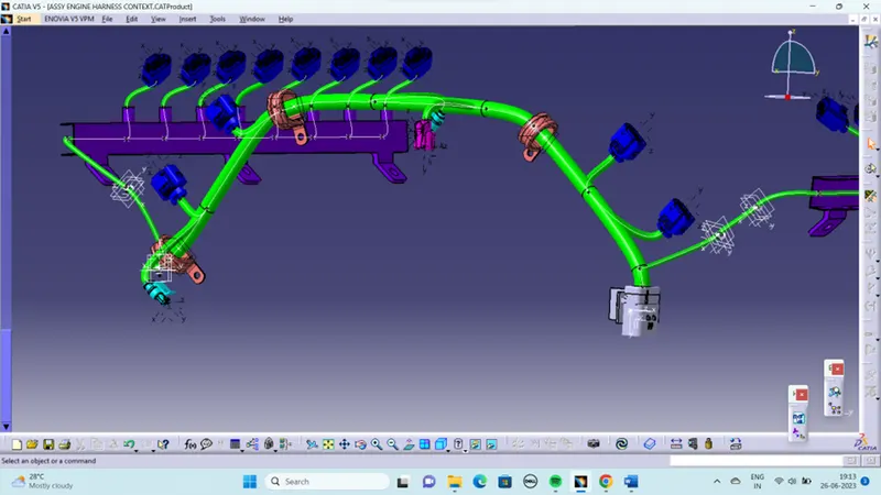
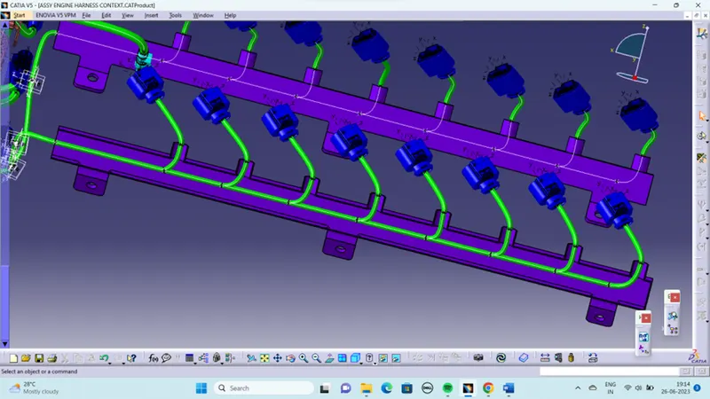
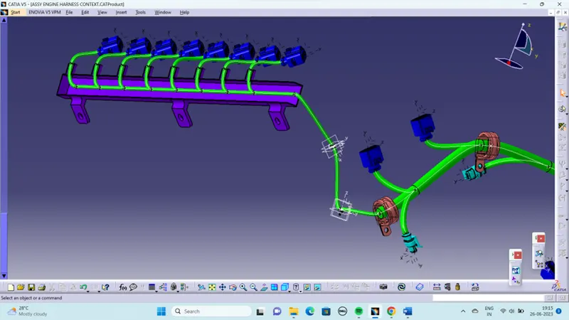
Add guiding channel for routing the wiring harness to the fuel injectors.it deals with clearance management and thermal protection of the wiring harness in the high temperature zones. Then request engine design team to provide additional threaded holes required to mount the guiding channels in proper location by using bolts or screws. After define the geometrical bundle electrically then select the multibranchable command to start the bundle routing and click on the route definition.
The bundle routing starts from interconnection connector and then to the P-clamps and to the guiding channels. Adding branche points to route the wiring harness from main branch to various connectors.
To route the wiring harness through the guiding channels, select external curve option and click on the line created in the guiding channel. Then add branch points to route the wiring herness from the guiding channel to the connectors. proper bend radius and slack provided for the bundle segment to avoid stress on the wire.
PROTECTION COVERING:
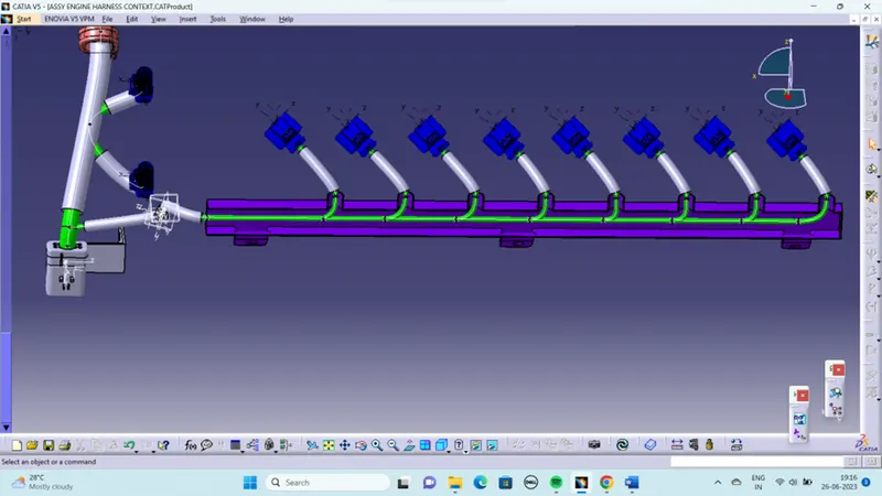
Add protective coverings on the wiring harness to protect wiring from high temperature. protective covering created by using define protection part command in the electrical part design workbench. Select part, and define the parameters as per the requirement.
The created corrugated tube can be added into the catalogue by store device command and selecting the catalogue file created for protective covering. then appropriate protective covering added to the bundle segments.
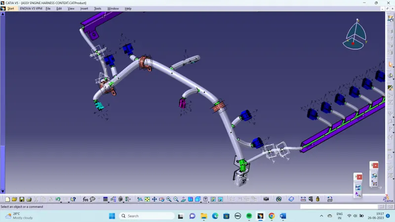
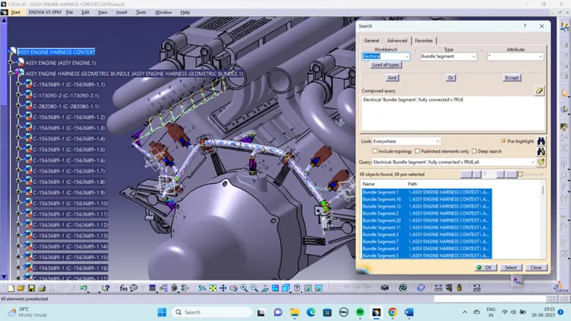
After the routing of harness bundle the I check the connectivity of the harness bundle.
DESIGN CRITERIA FOLLOWED TO ROUTE THE WIRING HARNESS:
- Distance between two clamps on a straight branch should be minimum of 200mm.
- The minimum branch length should be 50mm.
- Minimum distance between clip and nearest branching point should be 25mm.
- The minimum distance between two straight connection points should be 200mm.
- The minimum distance between two breakout points should be 50mm.
- To limit the number of branches from a single branch point to 4.
- Avoid routing wiring harness near the exhaust manifold and its components and also from other unshielded heat sources. If re-routing is not possible then maintain a minimum distance of 200mm.
- Try to avoid use of too many metal brackets on engine. Try to use the available threaded bosses on engine or demand for it.
- Enough clamps shall be provided to ensure positive clearance with surroundings and safety of wiring harness.
- P - Clamps, Fir tree clips and other clips can be added to the Geometric bundle as they are electrically defined and are part of the Wire harness routing and should be provided with the Wire bundle package.
- Enough slack should be provided to the wiring harness which help not to get damaged during the Engine rocking or starting condition.
- The wire harness routing should be done in such a way that it is easy in manufacturing and serviceability.
- The wire routing should be done keeping in mind the cost effectiveness of the bundle package.
- To avoid the harness routing and clipping in blind zones of the operator during the assembly and the service.
- To provide proper slack at end connectors so that there will be no tension on the wire bundle.
- To avoid sharp edges on the sheet metal parts and if it is not possible then provide protection parts to prevent damage of the wire bundle.
- To provide separate branch points for separate connectors to ensure Poka-Yoke.
HARNESS FLATTENING:
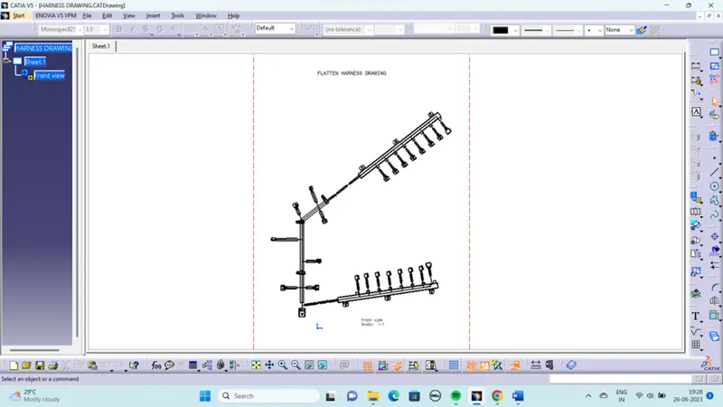
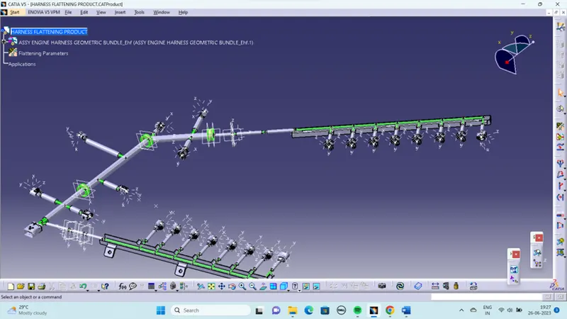
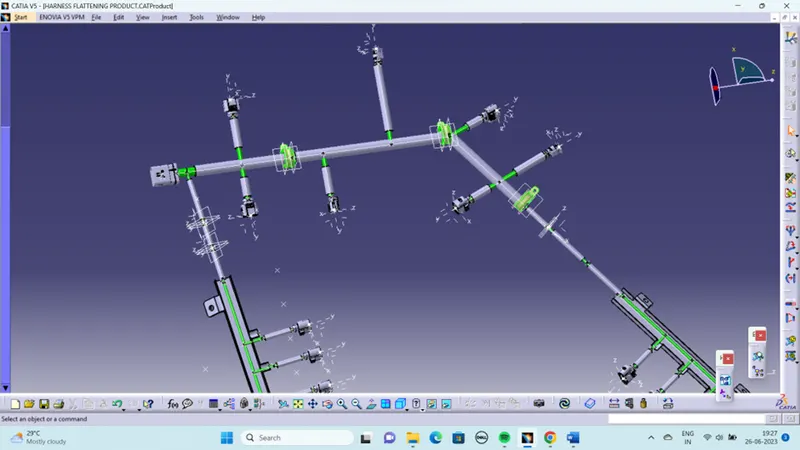
Create a new product file for flatten the wiring harness and save as in the same folder where the wiring harness is saved. Then switch to Electrical harness flattening workbench and select harness flattening parameters and define harness flattening parameters. Before creating flatten view, make sure that selecting 'Double line' for bundle segment and 'Double' line for protective covering.
STEPS TO FOLLOW:
- We go to the harness flattening workbench and define the flattening parameters.
- While defining the harness flattening parameters in the drawing menu single line is selected for bundle segment and double line is selected for protective coverings in order to differentiate between the wire bundle and cot tubes in drafting.
- We use the extract command to bring the harness assembly to the flattening workbench here.
- Then wire harness assembly is imported to the Wire flattening product file with 'EHF' extension added to the geometric bundle assembly name
- Choosing a suitable plane to flatten the harness assembly.
- Bundle segments are rotated at the required angles. The harness assembly is then drafted.
- Flattening parameters are defined in order to make the bundle and the corrugated tubes visible in the 3d drawings.
- Save the product file using 'Save management' option so that all the related product files and part files are stored in single directory.
DRAFTING:
- Create a new drawing file and save the file in the same location.
- Add the front view of the harness assembly Here I select the surface of the connector. and orient the view as per the requirement.
- Go to the properties of the view and select the '3D Wireframe' on and ' Is always visible' option in order to see properly the Wire bundle, connectors and the protection coverings.
- Then Naming the connectors and cot tubes.
- To add the length details of the bundle segments.