Project 1
Solution to Question 1:
Given data :
Rated capacity of the car = 150kw
Rated voltage = 120V
Nominal voltage of cell = 3.6V
Nominal current = 3500mAh
From the given data we can calculate :
Required number of cells in series = rated voltage/Nominal voltage = 120/3.6 = 33.33 = 34 cells
Rated current of the battery pack = Rated capacity/Rated voltage = 150K/120 = 1250A
Required number of cells in parallel = Rated current/Nominal current = 1250/3.5 = 357 cells.
Hence, the battery pack configuration will be 34S357P configuration.
For the obtained battery pack the BMS topology will be configured based on number of cells in series:
We have the following topologies of BMS:
1) Centralised topology
2) Modular topology
3) Master slave topology
4) Distributed topology
Depending on the number of cells connected in series we will be going to select the respective BMS topology. Here in our Battery configuration we have a total of 34 cells in series which is greater than 18 cells and less than 7000 cells. FOr this configuration we wil be going to use Master-Slave based BMS topology.
Pictorial representation of the Master slave topology can be illustrated by the below attached figure:

Solution ot Question 2:
The image below shows the configuration of 3S2P battery pack in MATLAB/Simulink software:
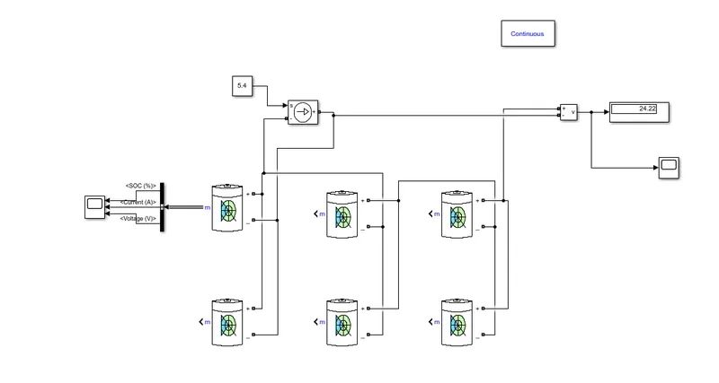
The specifications of individual cell is as given below:
Nominal voltage = 7.2V
Initial SOC = 100%
Rated capacity = 5.4Ah
In the model a controlled current source is connected across the cell 1 to make it act as a load across the cell
As the configuration is 3S2P the rated voltage across the pack will be 3x7.2 = 21.6V
Rated current across the pack will be 2x5.4 = 10.8A
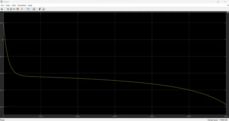
We can see the voltage measured across the pack is nearly equal to the calcualted voltage
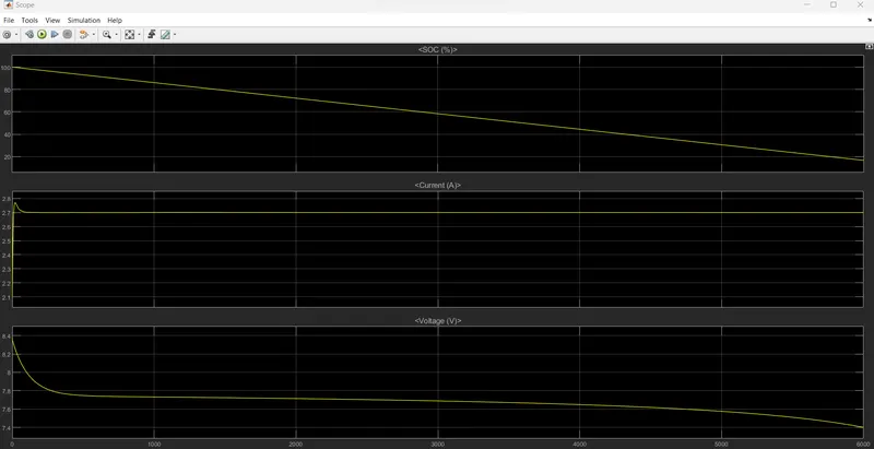
The following graphs shows the SOC, current and voltage across the cell 1:
The pack voltage is as shown below:
The circuit modelled is Simulink is attached here ofr reference.