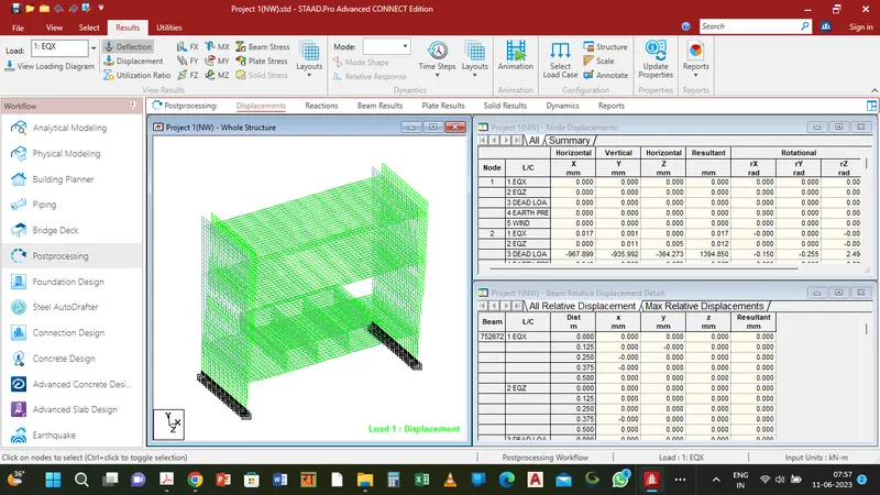
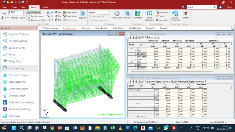
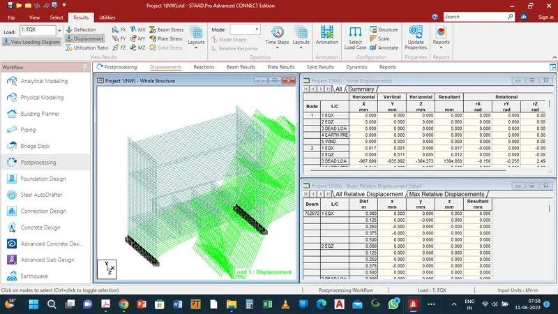
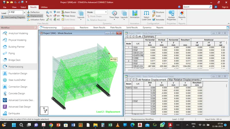
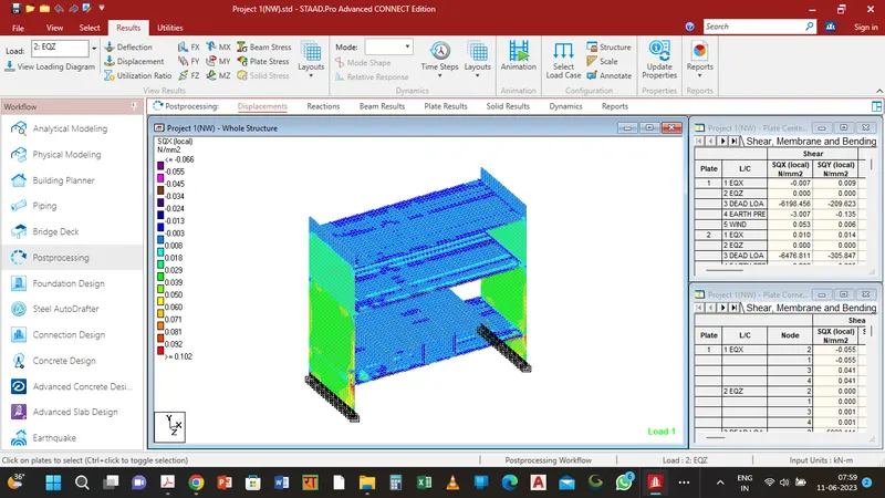
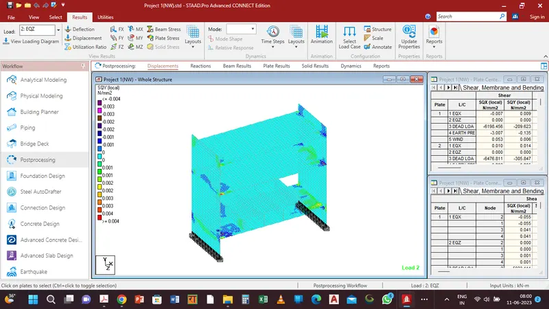
Project 1
To calculate the dead load, IRS live loads, earth pressure load, wind load, and seismic loads for the bridge structure at the Ahmedabad Metro rail project we have to refer to the given drawing and accordingly calculations are as follows:
- Dead Load: Assuming a reinforced concrete bridge deck and superstructure, we'll calculate the dead load.
Deck thickness (Assumed): 1.2 m Concrete density: 25 kN/m³ Steel density: 78.5 kN/m³
Volume = Length × Width × Thickness Volume = 260 m × 24 m × 1.2 m = 7488 m³
Dead Load = Volume × Unit Weight Dead Load = 7488 m³ × 25 kN/m³ = 187,200 kN
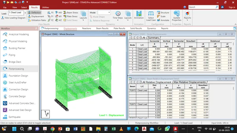
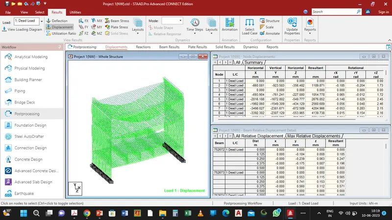
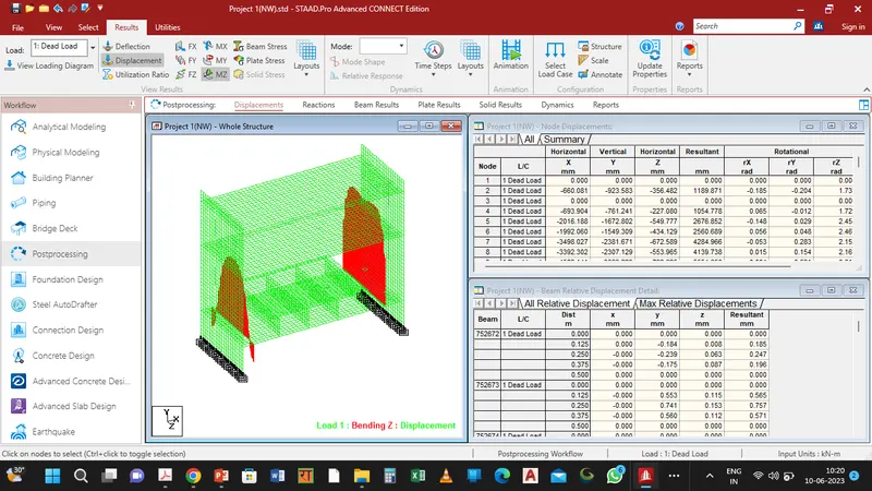
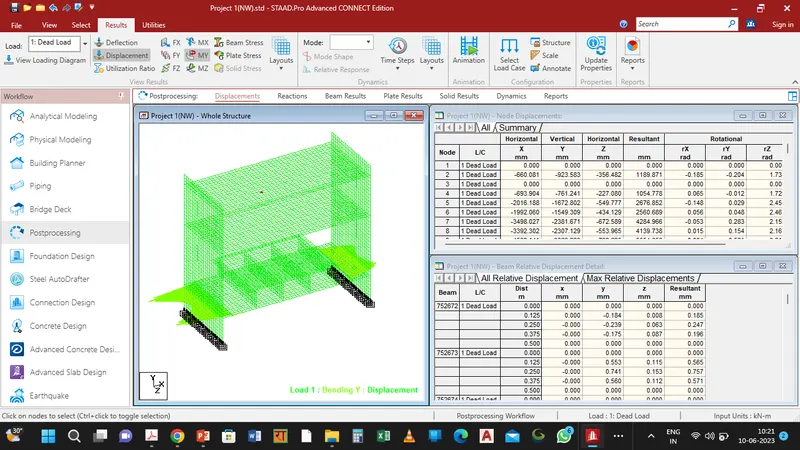
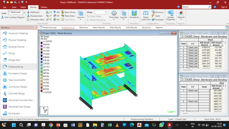
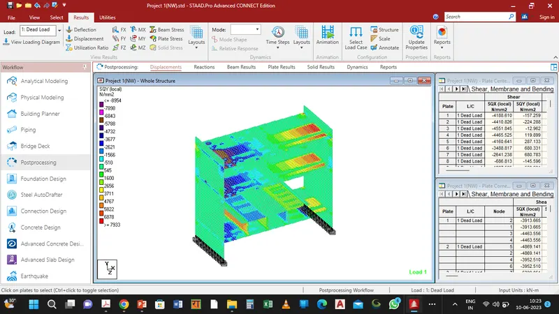
2. To calculate the Indian Railway Standard (IRS) live loads for the bridge structure at the Ahmedabad Metro rail project, considering the given data, we have to follow the IRS guidelines. The IRS provides guidelines for live load requirements for railway bridges in India. Here's is the calculation of the IRS live loads:
Given data: Bridge width: 24 m Span: 260 m Seismic zone: Zone III Wind speed: 39 km/hr Unit weight of soil: 18 kN/m³ Axle loading: 17 tons Maximum number of cars: 16 nos Wheel configuration lengths: a = 2150 mm b = 2200 mm c = 12400 mm d = 21100 mm
-
Lane Load: The lane load is typically expressed in terms of kN/m and represents the load per unit length of the bridge in each lane. For IRS Class A vehicles, the recommended lane load is typically 20 kN/m.
-
Design Load: To calculate the design load, we'll consider the maximum possible load on the bridge based on the given information. We'll assume that the bridge is subjected to a uniform distribution of vehicles.
IRS provides specifications for various design vehicles based on their axle configurations. The given axle loading is 17 tons.
Impact Factor: IRS recommends applying an impact factor to the design load to account for dynamic effects. For railway bridges, the impact factor is typically taken as 1.5.
Now, let's calculate the IRS live loads for the given bridge data:
IRS Class A Live Load: Lane Load: 20 kN/m (Assumed for Class A vehicles) Number of Lanes: 2 (Assuming a 2-lane bridge) Width of the Bridge: 24 m
Total Live Load for IRS Class A = Lane Load × Number of Lanes × Width of the Bridge = 20 kN/m × 2 × 24 m = 960 kN
IRS Class B Live Load: To calculate the live load for IRS Class B vehicles, we need to consider the maximum load on the bridge.
Assuming the maximum number of cars is 16 nos, we can distribute them evenly across the width of the bridge.
Length of each car = a + b + c + d = 2150 mm + 2200 mm + 12400 mm + 21100 mm = 37850 mm = 37.85 m
Spacing between each car = Span / (Number of Cars + 1) = 260 m / (16 + 1) = 14.44 m
Total Live Load for IRS Class B = (Axle Loading × Number of Axles) + (Lane Load × Number of Lanes) × Width of the Bridge
Total Live Load for IRS Class B = (17 tons × 4 axles × 16 cars) + (20 kN/m × 2 lanes × 24 m) = 1088 tons + 960 kN = 11928 kN
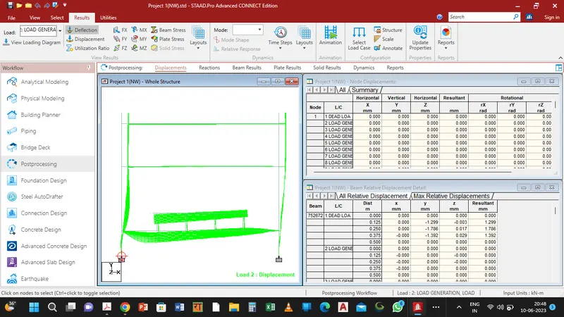
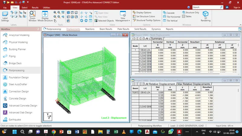
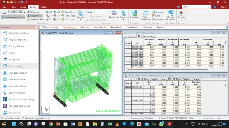
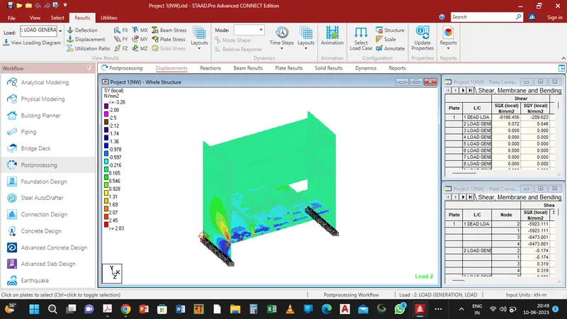
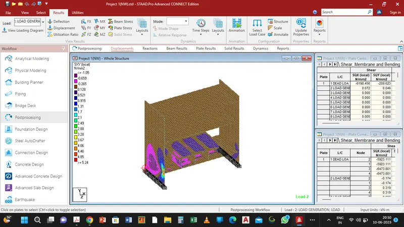
3. To calculate the earth pressure load for the bridge structure at the Ahmedabad Metro rail project, assuming a pier and abutment height of 12m and using the Indian Standard IS 875 Part 3 (Code of Practice for Design Loads - Earthquake Loads), we can estimate the lateral earth pressure.
Given data: Bridge width: 24 m Span: 260 m Unit weight of soil: 18 kN/m³ Assumed Height of piers and abutments: 12 m
a.Determine the Lateral Earth Pressure Coefficient (K): The lateral earth pressure coefficient depends on the backfill conditions and the angle of internal friction of the soil. Without specific information about the soil properties and backfill conditions, we can assume a typical value for K based on the soil type.
For granular soils, such as sand, the recommended value of K is 1.0.
b.Calculate the Active Earth Pressure: The active earth pressure can be calculated using the formula:
Pa = K × γ × H^2
where Pa is the active earth pressure, γ is the unit weight of soil, and H is the height of the abutment or pier.
Using the given data: γ = 18 kN/m³ H = 12 m K = 1.0 (Assumed for granular soil)
Pa = 1.0 × 18 kN/m³ × (12 m)^2 Pa = 1.0 × 18 kN/m³ × 144 m² Pa = 2592 kN
Therefore, the estimated earth pressure load for the bridge structure at the Ahmedabad Metro rail project is 2592 kN.
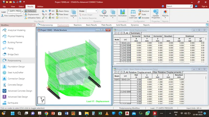
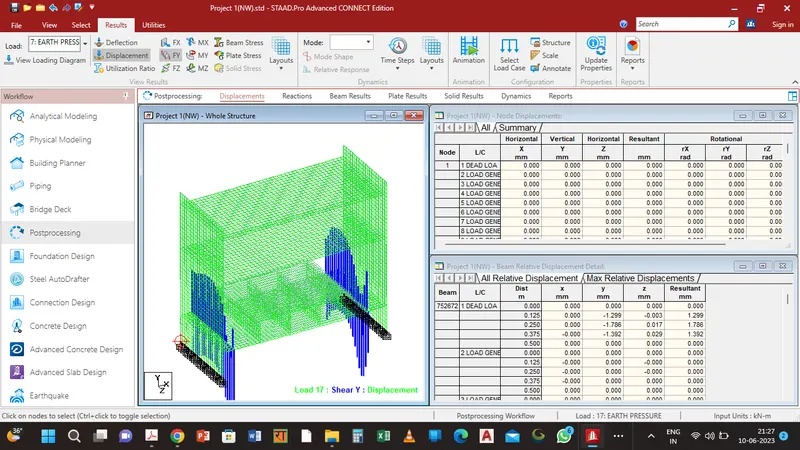
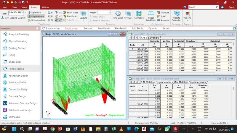
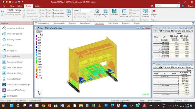
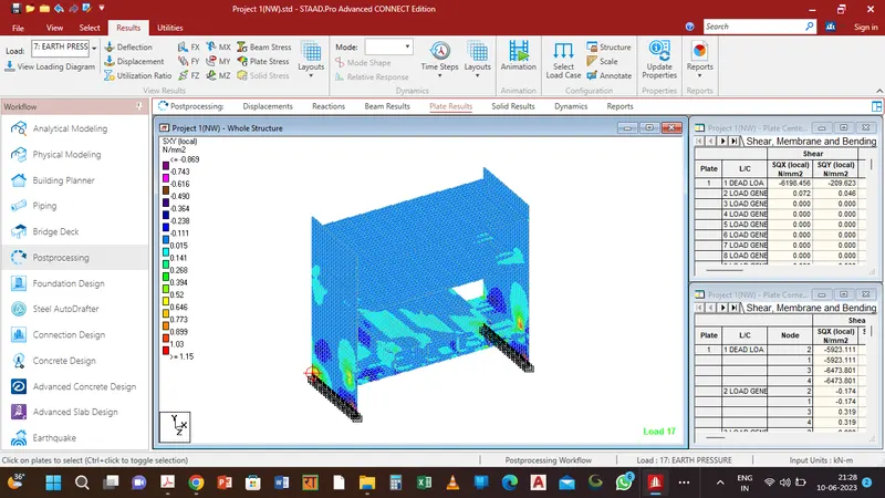
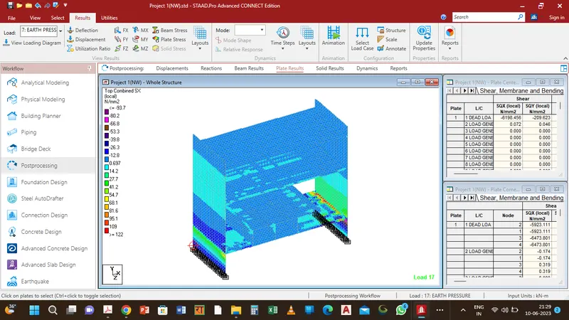
4. To calculate the wind load for the bridge structure at the Ahmedabad Metro rail project, we can use the provided data and the Indian Standard IS 875 Part 3 (Code of Practice for Design Loads - Wind Loads).
Given data: Bridge width: 24 m Span: 260 m Wind speed: 39 km/h Terrain Category: II Height: 12 m Importance factor: 1 Air density: 1.225 kg/m³
a. Convert the wind speed: Convert the wind speed from km/h to m/s: V = 39 km/h × (1000 m/3600 s) V = 10.83 m/s
b. Determine the Design Wind Speed (Vz): The design wind speed depends on the terrain category and height of the structure. Refer to Table 4 of IS 875 Part 3 to determine the appropriate factors.
For Terrain Category II and height of 12 m, the factors are: K1 = 0.98 (Exposure Factor) K2 = 1.0 (Topography Factor) K3 = 1.0 (Importance Factor)
Vz = V × K1 × K2 × K3 Vz = 10.83 m/s × 0.98 × 1.0 × 1.0 Vz = 10.61 m/s
c. Determine the Wind Pressure (P): The wind pressure can be calculated using the formula: P = 0.5 × ρ × Vz²
where P is the wind pressure, ρ is the air density, and Vz is the design wind speed.
P = 0.5 × 1.225 kg/m³ × (10.61 m/s)² P = 67.89 N/m²
d.Calculate the Wind Load (WL): The wind load can be calculated by multiplying the wind pressure by the projected area of the structure.
WL = P × A
where WL is the wind load, P is the wind pressure, and A is the projected area.
Assuming a rectangular shape for the bridge deck, the projected area can be calculated as:
A = Bridge width × Span A = 24 m × 260 m A = 6240 m²
WL = 67.89 N/m² × 6240 m² WL = 423,441.6 N = 423.4416 kN
Therefore, the estimated wind load for the bridge structure at the Ahmedabad Metro rail project is approximately 423,441.6 N
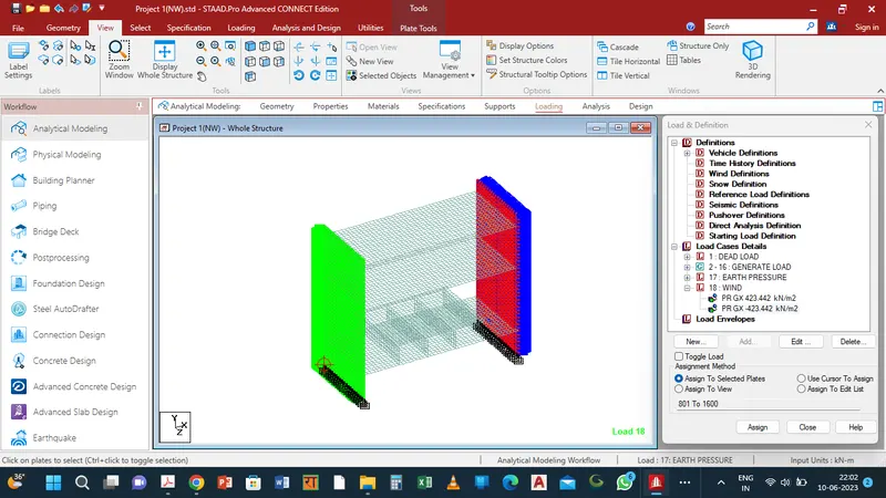
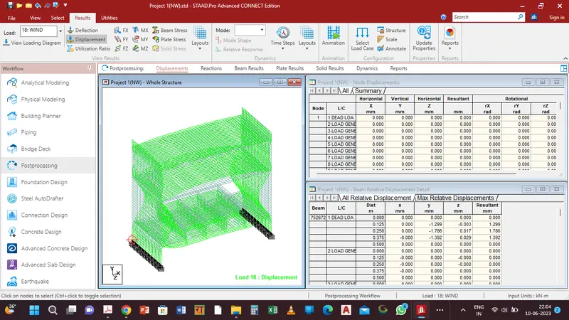
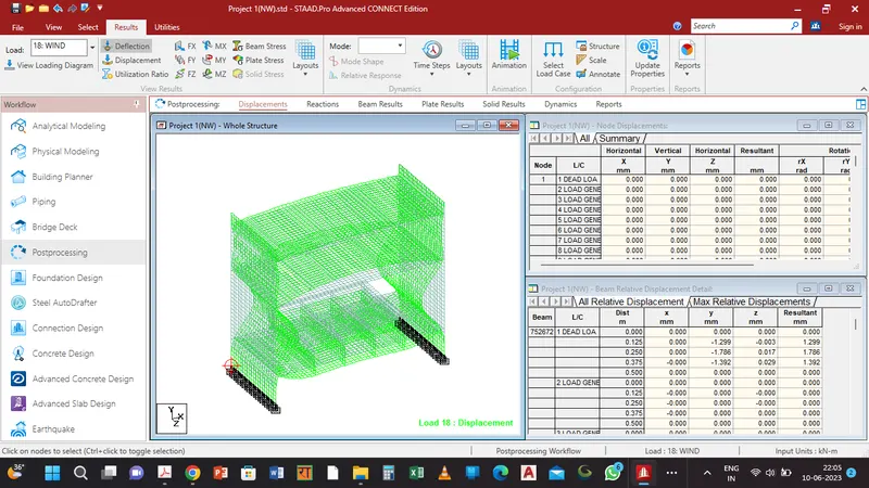
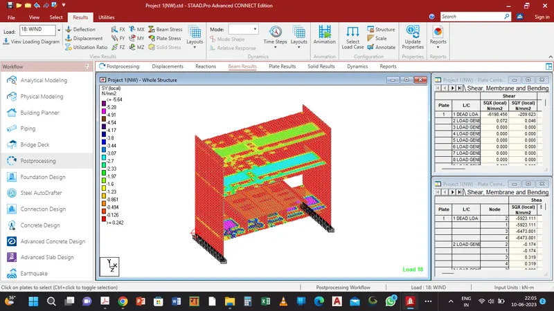
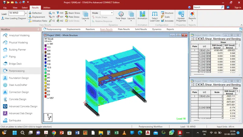
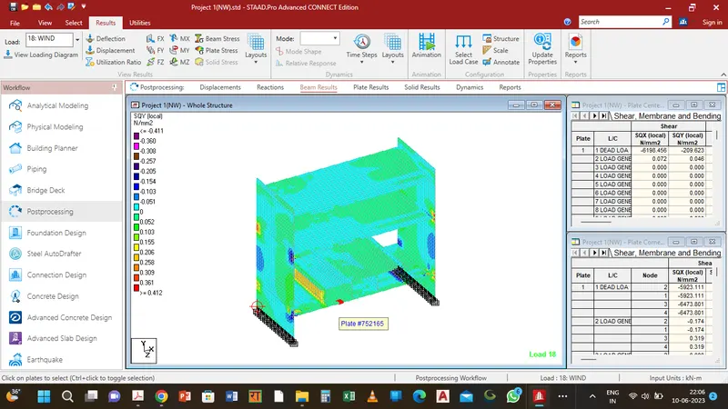
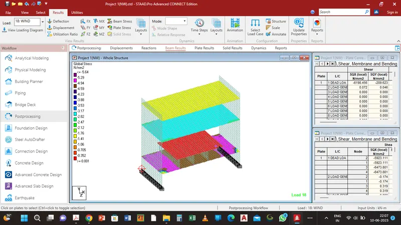
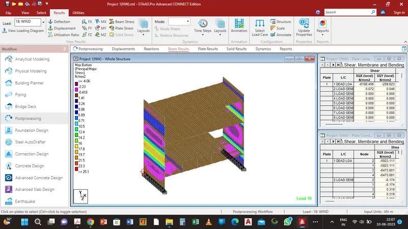
5. To calculate the seismic loads for the bridge structure at the Ahmedabad Metro rail project, using the given data and assuming suitable data, we can follow these steps:
Given data: Bridge width: 24 m Bridge Type: Girder Material: Steel Span length: 260 m Height of pier and abutment: 12 m Seismic zone: Zone III (Assumed) Soil bearing capacity: 180 kN/sq.m Response Reduction Factor (R): 5 Effective Seismic Weight (W): 2000 kN Design Horizontal Acceleration Coefficient (Ah): 0.16
A.Determine the Design Base Shear (Vb): The design base shear can be calculated using the formula:
Vb = Ah × R × W
where Vb is the design base shear, Ah is the design horizontal acceleration coefficient, R is the response reduction factor, and W is the effective seismic weight of the structure.
Vb = 0.16 × 5 × 2000 kN Vb = 1600 kN
B. Determine the Seismic Load Effects: To calculate the seismic load effects on the bridge structure, a detailed structural analysis is required. This analysis includes the following steps:
a. Determine the Dynamic Characteristics:
- Calculate the natural frequencies and mode shapes of the bridge structure using structural analysis software or formulas specific to girder bridges.
b. Determine the Seismic Force Distribution:
- Apply the appropriate seismic force distribution methods considering the bridge type (girder) and structural properties.
- Consider the mass distribution along the bridge, such as concentrated masses at piers and distributed masses along the span.
c. Calculate the Seismic Forces:
- Use the dynamic analysis results to determine the seismic forces, such as bending moments, shears, and axial forces, at critical sections of the bridge.
- Consider the effects of mode shapes, period of vibration, and modal participation factors.
d. Check the Structural Capacity:
- Compare the calculated seismic forces with the capacity of the bridge elements, such as beams, columns, and connections, to ensure they are within the design limits.
- Soil-Structure Interaction: Consider the interaction between the bridge structure and the soil by performing a soil-structure interaction analysis, if necessary. This analysis accounts for the dynamic behaviour of the soil and its effect on the bridge response.
- Detailed Design: Based on the calculated seismic loads and analysis results, design the bridge structure components, including members, connections, and foundations, to withstand the anticipated seismic forces.