Project 1
AIM
Route the Wiring harness on Given Engine and prepare flatten view drawing in CATIA V5. Application of all packaging rules, Industry best practices studied in design .Apply Protection coverings as requied.
ENGINE WIRING HARNESS ROUTING
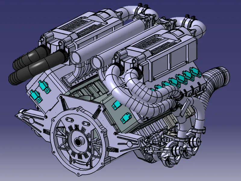
Given v16 engine
- The above figure shows the given v16 engine cad data . Here routing the wiring harness for the following electrical component attached to the engine .
- fuel injector for each cylinder we have 16 cylinder engine
- cam shaft sensor on each engine block
- Engine coolant sensor at the center of the engine between the two blocks
- Engine oil temperature and oil presure sensor fitted at the oil sump of the engine on both engine cylinder blocks
- sensor for sense neutral positon of the transmission assembly and measure the vehicle speed
- Interconnection connector to connect engine harness system to vehicle harness system .
- Harness mounting and routing management required to provide proper packaging of the wiring harness . I t also deals with clearance management and manufactrability.
- P- clamps to provide positve clamping and proper clearance management for the routing
- Mouting channels provide thermal protection in high temperature zones.
- Corrugated tubes used to protecct the wiring harness from harzardous liquids and temperature
- Next create a new product in assembly workbench namesd as assy_wiring_harness_context. It is the top level product file inside this product file crrated geomentrical bundle . and wirng harness electrical bundle . Given v16 Engine cad data added inside this contex assembly
- Geomentrical bundle contains all of the harness component should be defined electricaly .
- Download the 3d data of required connector and mountings from the site www.te.com
- define the connector electrically by define all its properties shown in the below fig.
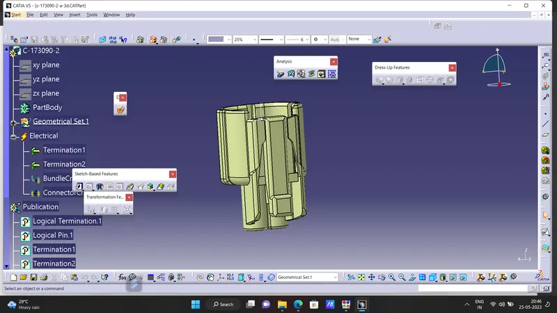
fig 1connector 2pole
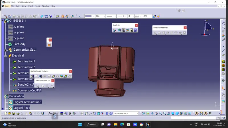
4 pole connector
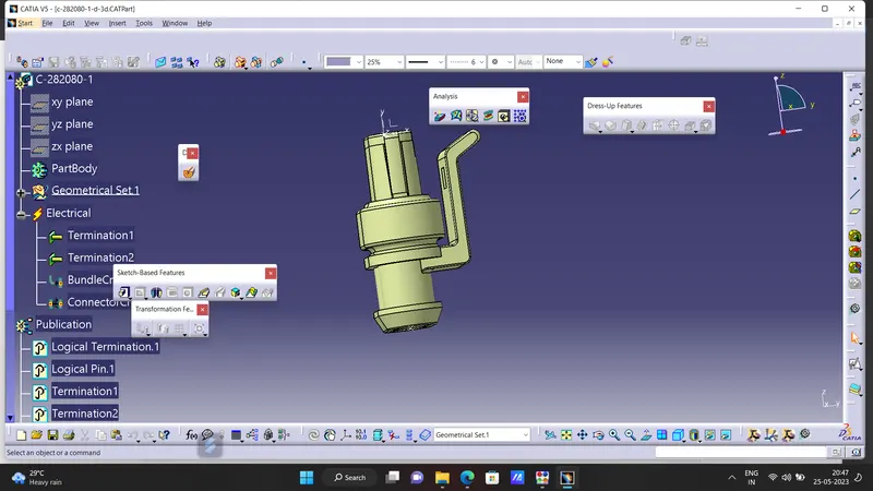
connector 2 pole
open the cad data of connetor s in catia part design workbench and create the connector connection axis systwm , bundle connection point .then switch to electrical part design workbench and define connector connection point and bundle connection point .
Here we have inter connection connector it reqire mounting clip for mounting the connector . So cavityy connection point should be define for this connector .
Mouting clip :-
- Define the mounting clip electrically by defineing all the properties. Define the clip as mounting equipment using mounting mounting equipment command . Select cavity command and define the parameters.
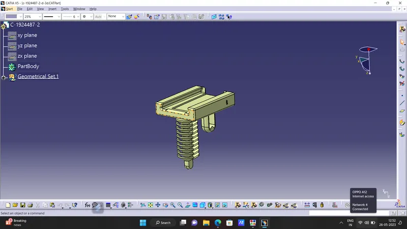
mouting clip for interconnection connector
P-clamp
First define geomentrical parameter such as entry point , entry plane ,exit point ,exit plane and base plane . then switch to electrical part design
workbench and using support command and define the parameter.

p-clam
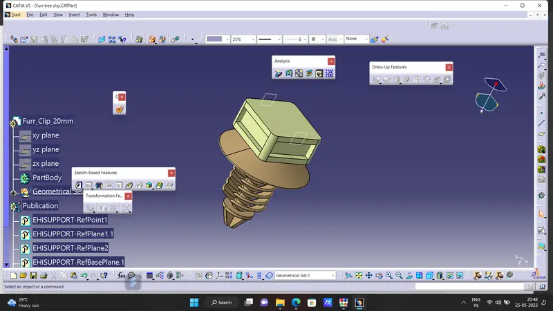
Furr tree clip
First define geomentrical parameter such as entry point ,entry plane ,eexit point ,exit plane and base plane .then switch to electrical part design workbench and define the fur-tree clip as support using support command and define the parameters.
Plastic guiding channels
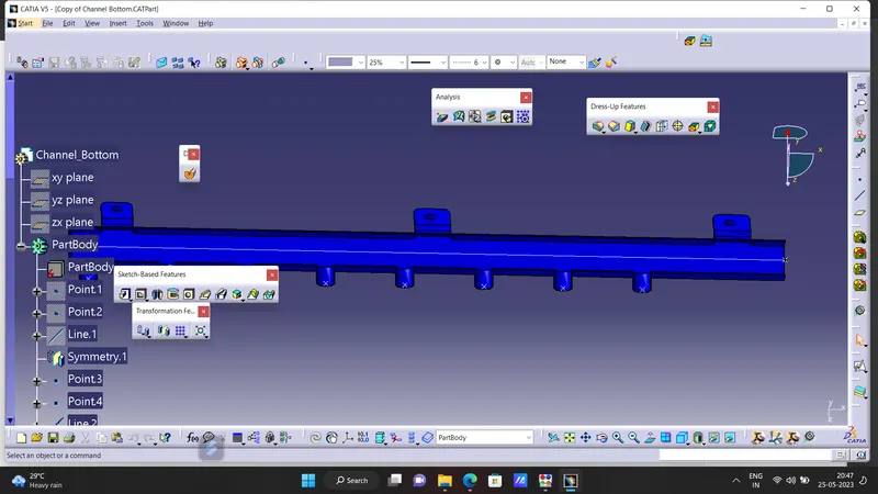
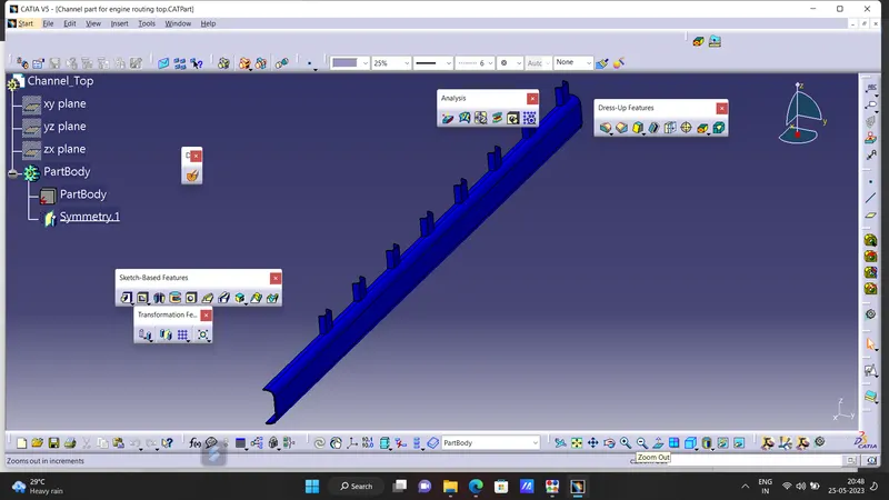
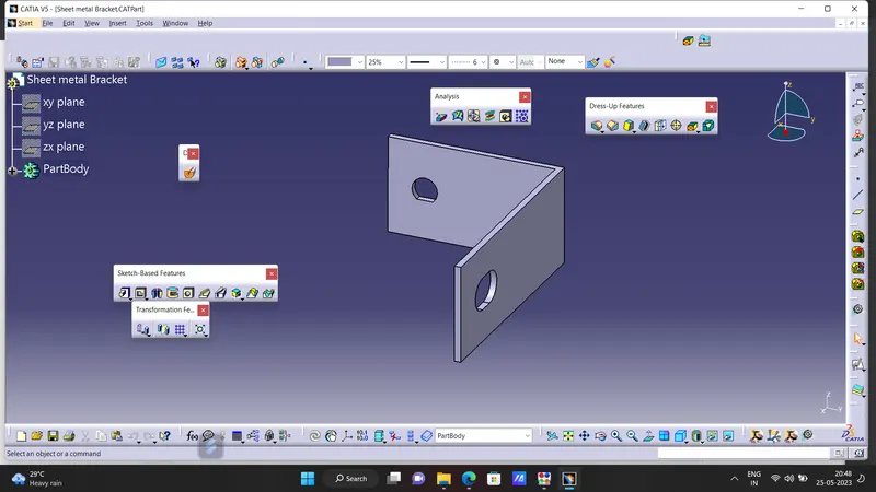
Sheet metal bracket
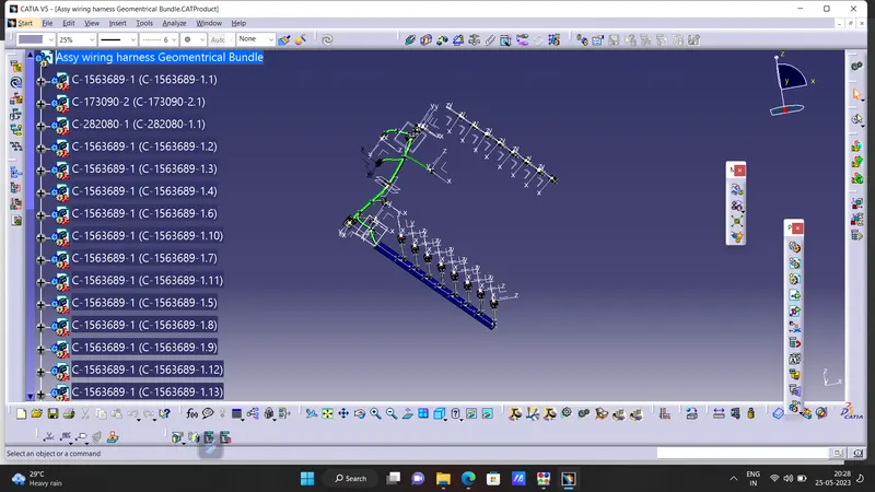
final wiring harness connection
bundle continuty 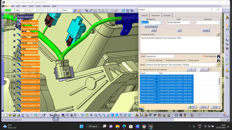
while flattening engine harness
before ,
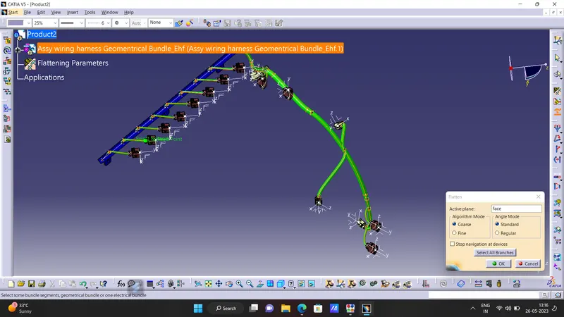
after
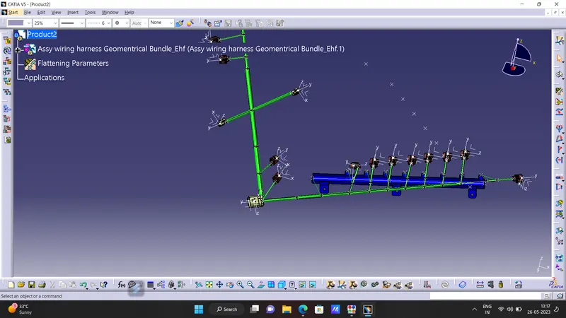
drawing of the flattened wiring harness 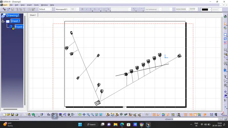
TO make the bundle segments visible right click on the drawing sheet and go to properties , in the view tab , highlight 3D wireframe and is always visible in the dress up settings .