Project 1
Engine Harness Wiring
Aim: To make a wiring connection of V16 engine, from main supply to cylinder, cam shaft, transmission set.
What is electric harness?
Wire harness design is the process by which an engineer evaluates the requirements of an electrical part of system, given available physical space to create an assembly of wires to deliver power and information as needed.
Processes of designing wiring for V16 Engine
We are given with the prepared V16 engine, we have to identify the electric point and make a wiring routing according to it.
Given Engine and its electric point:
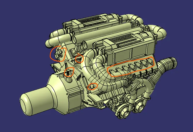
This is the given engine we have and oranges circles are electric point, normally this point are mentioned to us by provider or else we have to identify it. So, in our model we have identify the electric point and according to those points we have to select the connectors. In our model we are selecting the following connectors for different functions.
Connectors:
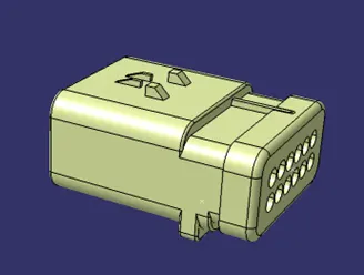
- C-776438-4 – Main supply connector: These connectors are taken from the com or the provide will provide us these details, we get this option from the supplier. This connector has 12 input terminals. This connector is electrically defined including connector to connector connection, bundle connection point and also number of terminals.
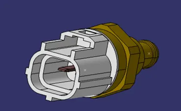
- Coolant Temp Sensor - Ford Duratec: This connector is provided to us by the supplier and it is not available at the com. So, if the connector is not available at the website the supplier will provide it all the necessary details and other details we have to guess. Also, this connector is electrically defined.
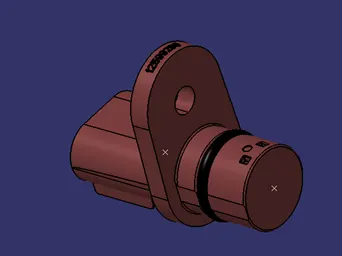
- Coolant Temp: This connector is also provided to us by the supplier and we had defined it as an electrical component.
Finalizing the wiring routing:
We have to identify the given environment and according to that we have to route the wire. In this model we had decided to use a channel for the engine connector as it will be suitable for the wiring aesthetic look, if we leave the wire open it will not look appealing and also can create the problem. So, to avoid this problem we will be using channel for the cylinder connector. Also, we had to put the L-Clamp for the main supply connection as it had to be mounted on something. “We have to inform the provider that we will be going to need this clamp at the required place”. As, the provider will not know that. So, this is how we had decided to route the electric bundle.
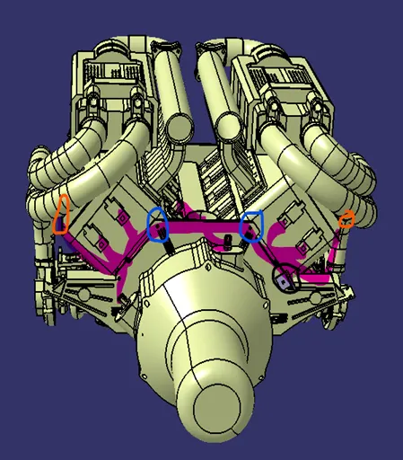
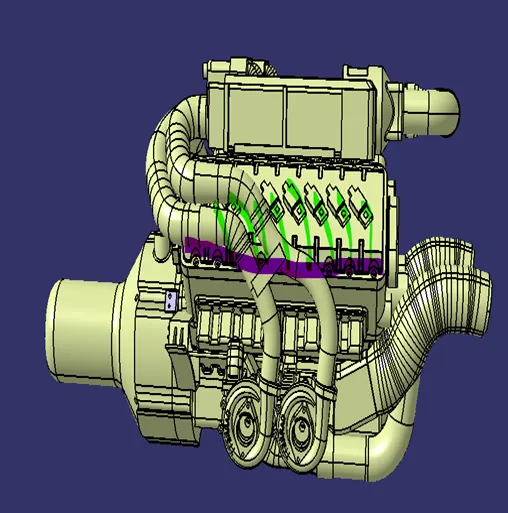
The above image shows the wiring that we have decided for the model. In first image,
- Pink color shows the wire routing
- Blue color shows the P-Clamps position
- Orange color shows the Channel inlet
- Black color shows L-Clamp position
In second image,
- Violete color shows the position of channel
- Green color shows the wiring into the connector
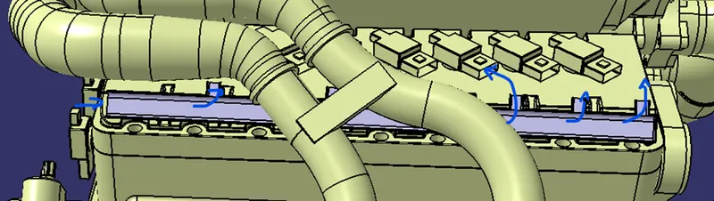
The channel that we had designed for the connection is also electrically defined and this how it looks.
Now, as we had put everything in the place we will do the Geometrically Bundle Routing like we did in the previous exercise.
After, the wiring routing is finished this is how the model will look.
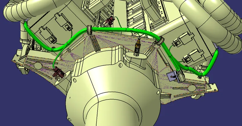
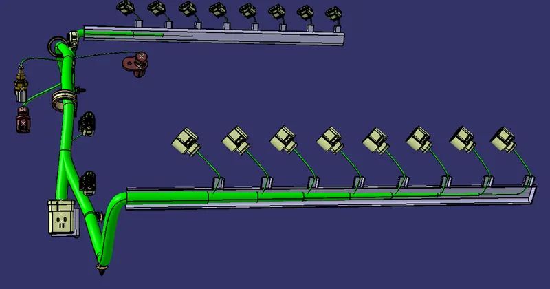
Once, the wiring is done it is necessary to provide the proper protection to the Geometrical Bundle. It will not only give protection but also the appealing look the Geometrical Bundle.
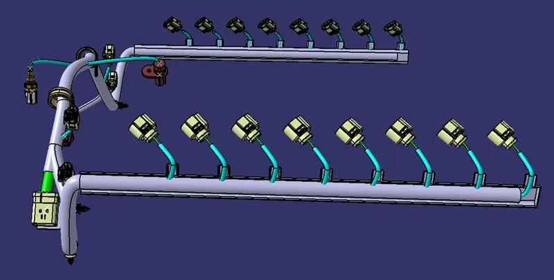
Flattening the wiring for the drawing:
The Geometrical Bundle is need to flattened in order to put it on the drawing sheet for the designer and other department to understand. The Geometrical Bundle is flattened and simplified in order to understand easily. We have to make sure to put proper flattening and use the flattening command to make it readable. The below is the look of wiring flattened.
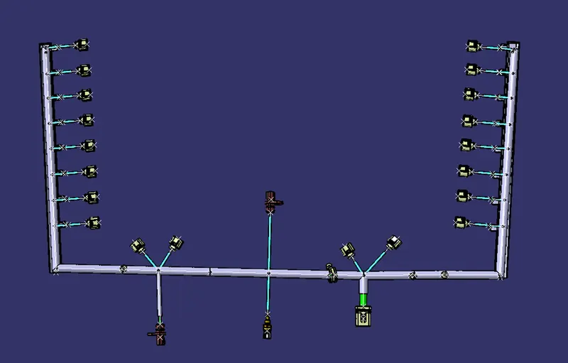
This flattened model is need to be transformed to the drawing sheet and then we will add all the details of the connectors and Cot_Tubes.
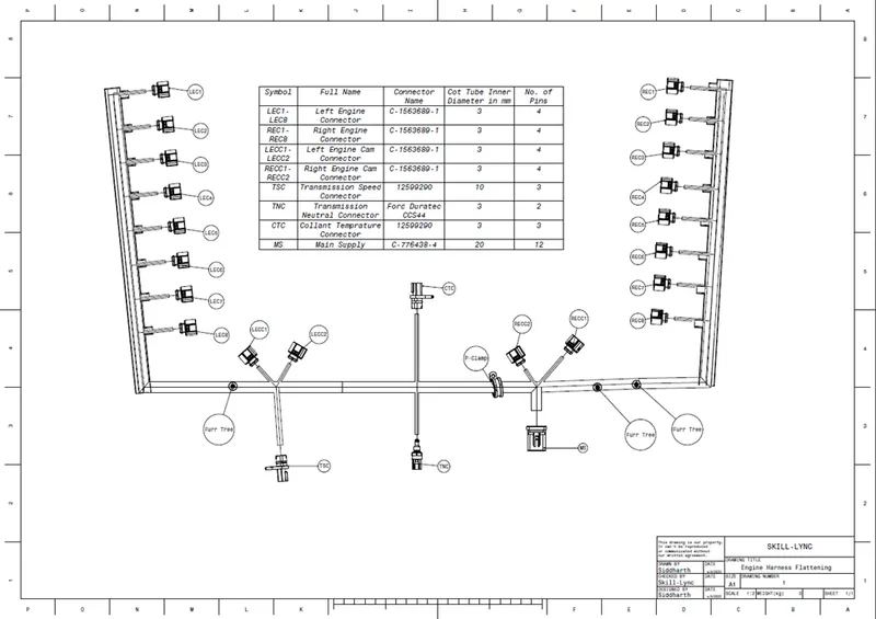
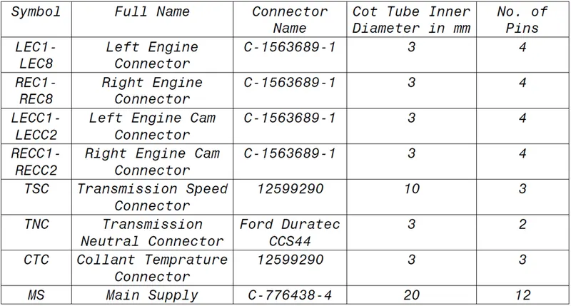
The table in the drawing gives the information about all the components, which is added below. It is necessary to added all the details that you can add in the drawing as this will define the drawing and make the drawing more easy to understand.
After the drawing is created it can be saved as PFD file. It can be sent to electric engineer so he can route the wire accordingly.
Result: The Electric Harness of the engine is successfully designed and also the flattening and drawing of the model is created.