Project 1
PROJECT 1
Aim: The main aim of this project is to gain the knowledge about the concept of design and analysis of an industrial building when subjected to the loading like lateral force such as wind and earthquake forces is understood and the various parameters that are to be taken into consideration while designing of an industrial building is learnt. And to determine the sizes that are required for the building to taken up the foces that are coming on to it.
Introduction: The portal frame structure is mainly composed of steel columns and roof beams, and the frame is a plane loading system. To ensure longitudinal stability, which column bracing and roof bracing will arrange.
The portal frame divided into several forms, 1. Typical portal steel frame. 2. Steel frame with the crane. 3. Steel frame with mezzanine structure.
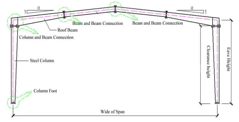
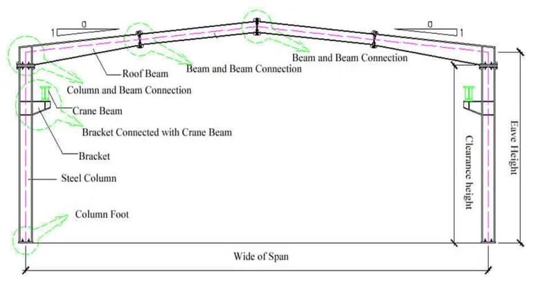
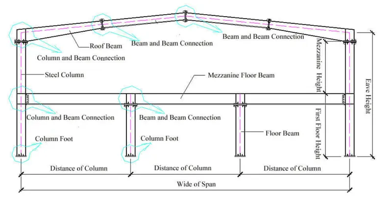
Bracing Structure
The portal frame, purlin Bracing system and the metal cladding rely on each other through reliable connection and support.
The main structure of the portal frame load-bearing structure divided into two types according to the kind of the rigid frame: the clear span structure without interior columns and the multi-span continuous structure with interior columns.
According to the specific project, it can also be used in single and multiple slopes, as well as in different spans and heights. Most of the foundation types adopt reinforced concrete independent foundations. According to the diverse requirements of the building for lateral displacement and deformation, from the perspective of saving steel, a variable-section beam-column, foundation hinge structure scheme, or an equal-section column variable-section beam, foundation rigid structure scheme can be adopted.
The main functions of the bracing system are:
1) The strut beam transmits the longitudinal horizontal force.
2) The horizontal bracing resists the horizontal force transmitted between the columns and roof beams.
3)Flange Bracing use to keep the stability of the outer plane
4) All bracing systems, together with purlin or wall girt and portal frames, which form a space system, which ensures the overall function of the space of the structure, bear, and transfers horizontal loads, and ensure the stability and convenience during the installation.
Purlin and Wall Girt
The main component types of purlins and wall girt are C-type or Z-type steel, and the size of the cross-section needs to determine through the load calculation. Compared with the Z-section, the mechanical properties of the C-section are quite different, C section steel connects to the portal frame bolted.
The Z-section can rigidly connect by substantial overlap, which can calculate as a continuous beam. Therefore, in addition to door and window openings and other specialized areas, Z-sections should be preferred. The distance between the purlin and the wall girt usually not exceed 1.5 meters.
The Applications of Steel Buildings
Steel structure buildings are not unfamiliar in our daily lives. In every corner of life, you can find steel structure buildings with a little attention. The application of steel structure buildings has been quite common. Today, let’s sort out where steel structure buildings are mainly used.
The steel buildings we are familiar with
- Steel structure workshop
Steel structure workshops are generally divided into light steel structure workshops and heavy steel structure workshops.
Regular industrial steel structure workshops are generally light steel structure workshops, such as chemical plants, breweries, door and window factories, glass factories, farms, farms, etc. The light structure of the roof and outer walls of the steel structure factory building usually uses H-shaped steel as the beam and column surface, and the joints are rigid connections. The steel structure factory building comprises beams, steel beams, braces, roof panels, wall panels, etc.
The heavy steel structure workshops are basically equipped with cranes. Steel skeletons are often used in workshops with heavy crane lifting capacity or heavy work. Such as the open hearth, converter workshop, they are mixing furnace workshop, blooming workshop of the metallurgical plant, the steel casting workshop, hydraulic press workshop, and forging workshop of the heavy machinery plant.
- Steel structure warehouse
The material and structure of steel structure warehouses are similar to those of regular light steel structure workshops. Still, the design of steel structure warehouses is relatively simple. The materials are more practical, the cost is relatively low, the load-bearing capacity is rather large, and the materials can be recycled and used.
Relatively simple steel building:
- Steel structure foyer
It is an annex hall that expanded on the original building or the factory building. This kind of architectural hall design in advance through a computer, and the construction period is shorter, and the workload is less, so the installation is faster.
- Steel structure flyover
This kind of flyover would like to say that there are fewer procedures, no need for pouring and maintenance, the construction speed is relatively fast, and the disassembly is very convenient. The recycling value is relatively high. Therefore, it is suitable for quick and civilized construction.
- Steel structure platform
The steel structure platform is designed according to the actual situation of the building to make full use of the original space, improve the utilization rate of the area, and assist the production work. Therefore, the steel structure platform widely uses in people’s production and life. The more common steel structure platforms mainly use factories, logistics storage warehouses, steel structure stages, cinema platforms, etc.
- Steel structure canopy
Many building communities and shopping malls use steel structure canopies to decorate their stores, which are beautiful, economical, and applicable and shelter people from wind and rain. The use of steel canopy brings a lot of convenience to people’s lives.
- Steel structure residence
Steel structure houses and steel structure villas are not very rare buildings anymore. Much rural self-contained housing, factory dormitories, hotels, tourist attractions, etc., are already using steel structure residential houses.
More complex steel buildings
- Large span structure
Such as aircraft assembly workshops, hangars, conference halls, stadiums, exhibition halls, high-speed railway stations, large shopping malls, etc., all require large-span structures. Its structural system can be net frame, suspension cable, arch frame, and frame, etc. Compared with steel structure workshops and warehouses, the structure and design are more complicated.
- Tower mast structure
Including tower mast structures, such as TV towers, microwave towers, transmission line towers, drilling towers, environmental atmospheric monitoring towers, radio antenna poles, broadcast transmission masts, etc.
- Multi-storey, high-rise, and super high-rise buildings
The framework of multi-story and high-rise buildings can adopt steel structures. For multi-story frames in industrial buildings and high-rise or super high-rise buildings such as hotels, restaurants, office buildings, frame structure systems, frame support systems, and frame shear wall systems should be adopted. In recent years, steel structure has been gradually developed in this field.
- Removable or movable structure
Mobile houses for commerce, tourism, and construction sites are mostly lightweight steel structures connected with bolts or fasteners.
- Other structures
Such as trestle bridges, pipeline supports, derricks, and offshore oil production platforms.
The application of steel structure building is more extensive; due to its advantages, the proportion of steel structure building will become larger and larger. The national government strongly supports the development of steel structure buildings. It appeals to the people to hide steel, which is also a general trend in the development of the construction industry in the future.
How to improve the efficiency of steel structure buildings?
We all know that steel frame buildings’ rapid development and popularity largely depend on steel structure construction’s high efficiency to build a workshop or warehouse. The owner wants to put it into use as soon as possible to get profits. Steel structure building is the first choice. Because if you choose to use a steel structure, from planning to putting it into use, it can be completed within a few months if the progress is smooth. So in what ways can steel structure building improve efficiency?
- Design efficiency
The first and most crucial step at the beginning of steel structure building is drawing, planning and design. Nowadays, it takes much less time to design steel structures than in the past. The first is that the designer has rich experience, but the designer uses various accurate computer software to increase the design speed a lot. Designers can use design software to simulate and design a solid structure and use as little steel as possible to make the most reasonable design within the safe range of values so that the price can keep at a low level.
- Production efficiency of steel components
After the design drawing is confirmed, the factory will fabricate the components according to the drawing. Choosing the proper steel structure factory is very important because selecting the right factory can improve the quality and speed of component fabrication. It’s not that the bigger the factory, the better. If your building is not very large, it may not be wise to find a large-scale steel structure factory. Because when the factory is busy, it is possible to delay your component manufacture time and affect the efficiency of component production. Of course, it is best not to choose a steel structure factory that is too small because a factory that is too small may not strictly follow the fabrication standards of the components to reduce costs. It will not arrange professional quality inspectors to conduct quality supervision.
- Transportation efficiency
The packaging and transportation of steel components is also an essential part of it. Especially for international projects, inexperienced factories are not familiar with the packaging and transportation of steel components. Improper packaging and transportation may cause damage to the steel components and affect the progress of the entire project.
- Installation efficiency
The quality of steel structure installation determines the quality of the entire steel structure building. It is best to choose an experienced and professional installation team to ensure installation efficiency. Generally, the installation time of steel structure buildings is one-third less than the construction time of other building systems.
- Operational efficiency
The maintenance cost of the steel structure building is meager, and the number of repairs required is also small. Equipped with an effective thermal insulation system will also reduce prefab metal buildings’ energy costs.
- Use efficiency
The steel structure building has a long service life. If the design is reasonable, the component quality is qualified, and the maintenance is timely, the steel structure building can be used for more than 50 years. When the service life of the metal building exceeds its service life, the steel components can be 100% recycled, saving money.
The different types of loads that are to be considered while designing the pipe racks are as follows:
- Dead load
- Live load
- Wind load
- Earthquake load
Dead Loads (D): The PIP Structural Design Criteria prescribes specific dead loads for pipe racks. Pipe racks and their foundations should be designed to support these loads applied on all available rack space, unless other criteria is provided by the client.
Structure dead load (Ds): The weight of materials forming the structure and all permanently attached appurtenances. This includes the weight of fire protection material, but does not include the weight of piping, cable trays, process equipment and vessels.
Operating dead load (Do): The operating dead load is the weight of piping, piping insulation, cable tray, process equipment and vessels plus their contents (fluid load). The piping and cable tray loads may be based on actual loads or approximated by using uniform loads.
Empty dead load (De): The empty weight of piping, piping insulation, cable tray, process equipment and vessels. When using approximate uniform loads, 60% of the operating dead load for piping levels is typically used. Engineering judgment should be used for cable tray levels.
Test dead load (Dt): The empty weight of the pipes plus the weight of the test medium.
Live load: Live load is one of the gravity load imposed by liquid or viscous materials in pipes during the operation along with which the human load is also added to it. Live load is defines as the load which is produced by the use and the occupancy of the structure thus not including any kind of construction or the environmental loads. Live load generally comes around the platform area, staircase and at the places where the access for the maintenance is provided.
Wind Load: Transverse wind load on structural members, piping, electrical trays, equipment, platforms, and ladders should be determined in accordance with project approved design code. Longitudinal wind should typically be applied to structural framing, cable tray vertical drop (if any), large dia pipes vertical drop (if any) and equipment only. The effects of longitudinal wind on piping and trays running parallel to the wind direction should be neglected.
Earthquake Loads: Earthquake loads in the vertical, transverse, and longitudinal directions should be determined in accordance with the project design criteria. Vertical, transverse, and longitudinal seismic forces generated by the pipes, raceways, supported equipment, and the pipe rack structure should be considered and should be based on their operating weights. Pipes must be evaluated for seismic loads under both full and empty conditions and then combined with the corresponding gravity loads.
Model & Design a Proposed Coil Centre, Chennai using STAAD. Pro for following input from Client
Design only a Main Frame with Lean (Grid 2) & Gable Frame without Lean (Grid 15)
Assume purlin load as 8.77 kg/m
Assume Gantry girder wt. = 158.24 kg/m
Assume Rail weight = 53 kg/m
|
Proposed Coil Centre, Chennai |
|||||
|
Sl.No |
Parameter |
Value |
Data From |
Remark |
|
|
AREA-01 |
|||||
|
Building Parameters |
|||||
|
1 |
Building Width |
30000.00 mm |
Client |
Out to Out of Steel |
|
|
2 |
Width Module |
Clear Span |
Client |
||
|
3 |
Building Length |
140000.00 mm |
Client |
Center to Center of Steel Column |
|
|
4 |
Building Height |
11100.00 mm |
Client |
Clear Height from FFL |
|
|
5 |
Roof Slope |
1:10 |
Client |
||
|
6 |
Column Base |
Fixed Base |
Assumed |
To control Deflection |
|
|
7 |
Bay Spacing (in mm) Main frame with Rafters |
14@10000 |
Client |
Center to Center of Steel Column |
|
|
8 |
Roof Bracing |
Diagonal Angle Bracing |
Client |
||
|
9 |
Wall Bracing |
Portal Bracing and above Angle Bracing |
Client |
Up to 6.5m Portal Bracing |
|
|
10 |
End Wall Type |
Rigid Frame |
Assumed |
||
|
End Wall |
|||||
|
1 |
LEW Bay Spacing |
9800+10400+9800 |
Assumed |
Out to Out of Steel |
|
|
2 |
REW Bay Spacing |
9800+10400+9800 |
Assumed |
Out to Out of Steel |
|
|
Sheeting Specifications |
|||||
|
1 |
Roof Sheeting |
Single Skin Panel |
Client |
0.55mm Galvanized Standing Seam Panel |
|
|
2 |
Wall Sheeting |
Single Skin Panel |
Client |
0.5mm Galvanized Painted (CCGL) Panel |
|
|
3 |
Trims & Flashings |
Assumed |
0.5mm Galvanized Painted Trim |
||
|
Wall Sheeting Condtions |
|||||
|
1 |
Near Side Wall |
Brick wall and above Sheeting |
Client |
Up to 2.80m Brick wall from FFL |
|
|
2 |
Far Side Wall |
Opening and above Sheeting |
Client |
Up to 10.60m Open for access to Existing building |
|
|
3 |
Left End Wall |
Brick wall and above Sheeting |
Client |
Up to 2.80m Brick wall from FFL |
|
|
4 |
Right End Wall |
Brick wall and above Sheeting |
Client |
Up to 2.80m Brick wall from FFL |
|
|
Eave Condition |
|||||
|
1 |
Near Side Wall |
Eave Gutter with PVC Downspout |
Client |
||
|
2 |
Far Side Wall |
Eave Gutter with PVC Downspout |
Client |
||
|
Crane System |
|||||
|
1 |
Crane Capacity |
30MT |
Client |
EOT Crane (Pendant Operated) |
|
|
2 |
C/C of Crane Rail |
27410.00 mm |
Assumed |
Approximate dimension |
|
|
3 |
No. of Cranes |
1 |
Client |
||
|
4 |
Run Length |
Full Length |
Client |
Along GL. 1 to 15 B/W C' & D' |
|
|
5 |
Crane Height |
7500.00 mm |
Client |
Top of Crane Beam from FFL |
|
|
6 |
Bracing Below CB |
Portal Bracing |
Assumed |
||
|
7 |
Crane Data |
Crane weight incl. hoist |
35.0 MT |
Assumed |
|
|
No of wheels |
4 |
Assumed |
|||
|
Wheel Base |
5800.00 mm |
Assumed |
|||
|
Bumper distance |
6200.00 mm |
Assumed |
|||
|
Maximum Wheel Load |
262.00 KN |
Assumed |
|||
|
Vertical Impact |
25.00% |
Code |
As per IS 875 |
||
|
Lateral Impact |
20.00% |
Code |
As per IS 875 |
||
|
Longitudinal Impact |
10.00% |
Code |
As per IS 875 |
||
|
Loading Class |
2 |
Assumed |
As per AISC 1989 |
||
|
Crane System |
|||||
|
1 |
Crane Capacity |
20MT |
Client |
EOT Crane (Pendant Operated) |
|
|
2 |
C/C of Crane Rail |
27410.00 mm |
Assumed |
Approximate dimension |
|
|
3 |
No. of Cranes |
1 |
Client |
||
|
4 |
Run Length |
Full Length |
Client |
Along GL. 1 to 15 B/W C' & D' |
|
|
5 |
Crane Height |
7500.00 mm |
Client |
Top of Crane Beam from FFL |
|
|
6 |
Bracing Below CB |
Portal Bracing |
Assumed |
||
|
7 |
Crane Data |
Crane weight incl. hoist |
25.0 MT |
Assumed |
|
|
No of wheels |
4 |
Assumed |
|||
|
Wheel Base |
4500.00 mm |
Assumed |
|||
|
Bumper distance |
5124.00 mm |
Assumed |
|||
|
Maximum Wheel Load |
165.00 KN |
Assumed |
|||
|
Vertical Impact |
25.00% |
Code |
As per IS 875 |
||
|
Lateral Impact |
20.00% |
Code |
As per IS 875 |
||
|
Longitudinal Impact |
10.00% |
Code |
As per IS 875 |
||
|
Loading Class |
2 |
Assumed |
As per AISC 1989 |
||
|
Sl.No |
Parameter |
Value |
Data From |
Remark |
|
|
Crane System |
|||||
|
1 |
Crane Capacity |
15MT |
Client |
EOT Crane (Pendant Operated) |
|
|
2 |
C/C of Crane Rail |
27410.00 mm |
Assumed |
Approximate dimension |
|
|
3 |
No. of Cranes |
1 |
Client |
||
|
4 |
Run Length |
Full Length |
Client |
Along GL. 1 to 15 B/W C' & D' |
|
|
5 |
Crane Height |
7500.00 mm |
Client |
Top of Crane Beam from FFL |
|
|
6 |
Bracing Below CB |
Portal Bracing |
Assumed |
||
|
7 |
Crane Data |
Crane weight incl. hoist |
18.4 MT |
Assumed |
|
|
No of wheels |
4 |
Assumed |
|||
|
Wheel Base |
4500.00 mm |
Assumed |
|||
|
Bumper distance |
5010.00 mm |
Assumed |
|||
|
Maximum Wheel Load |
123.00 KN |
Assumed |
|||
|
Vertical Impact |
25.00% |
Code |
As per IS 875 |
||
|
Lateral Impact |
20.00% |
Code |
As per IS 875 |
||
|
Longitudinal Impact |
10.00% |
Code |
As per IS 875 |
||
|
Loading Class |
2 |
Assumed |
As per AISC 1989 |
||
|
Roof Extension - Far Side wall Along GL-C' |
|||||
|
1 |
Length |
6000.00 mm |
Client |
||
|
2 |
Location |
Far Side wall Along GL-C' |
Client |
||
|
3 |
Slope |
1:10 |
Client |
||
|
4 |
Eave Condition |
Eave Gutter with PVC Downspout |
Client |
||
|
AREA-02 (Lean to) |
|||||
|
Building Parameters |
|||||
|
1 |
Building Width |
5000.00 mm |
Client |
Out to Out of Steel |
|
|
2 |
Width Module |
Clear Span-Monoslope |
Client |
||
|
3 |
Building Length |
30000.00 mm |
Client |
Center to Center of Steel Column |
|
|
4 |
Building Height (GL-D1') |
6000.00 mm |
Client |
Clear Height from FFL |
|
|
5 |
Roof Slope |
1:10 |
Client |
||
|
6 |
Column Base |
Pinned Base |
Assumed |
||
|
7 |
Bay Spacing (in mm) |
3@10000 |
Client |
Center to Center of Steel Column |
|
|
8 |
Roof Bracing |
Diagonal Angle Bracing |
Client |
||
|
9 |
Wall Bracing |
Portal Bracing |
Client |
Up to Full height |
|
|
10 |
End Wall Type |
Rigid Frame |
Assumed |
||
|
End Wall |
|||||
|
1 |
LEW Bay Spacing |
5000.00 mm |
Assumed |
Out to Out of Steel |
|
|
2 |
REW Bay Spacing |
5000.00 mm |
Assumed |
Out to Out of Steel |
|
|
Sheeting Specifications |
|||||
|
1 |
Roof Sheeting |
Single Skin Panel |
Client |
0.55mm Galvanized Standing Seam Panel |
|
|
2 |
Wall Sheeting |
Single Skin Panel |
Client |
0.5mm Galvanized Painted (CCGL) Panel |
|
|
3 |
Trims & Flashings |
Assumed |
0.5mm Galvanized Painted Trim |
||
|
Wall Sheeting Condtions |
|||||
|
1 |
Near Side Wall |
Brick wall and above Sheeting |
Client |
Up to 2.80m Brick wall from FFL |
|
|
2 |
Far Side Wall |
Brick wall and above Sheeting |
Client |
Up to 2.80m Brick wall from FFL |
|
|
3 |
Left End Wall |
Brick wall and above Sheeting |
Client |
Up to 2.80m Brick wall from FFL |
|
|
4 |
Right End Wall |
Brick wall and above Sheeting |
Client |
Up to 2.80m Brick wall from FFL |
|
|
Eave Condition |
|||||
|
1 |
Near Side Wall |
Eave Gutter with PVC Downspout |
Client |
||
|
2 |
Far Side Wall |
Peak trim |
Client |
||
|
GENERAL PARAMETERS |
|||||
|
Loads & Design |
|||||
|
1 |
Dead Load |
0.14 KN/m2 |
Assumed |
||
|
2 |
Coll Load |
0.15 KN/m2 |
Client |
False ceiling load for Roof extension alone |
|
|
3 |
Live Load |
0.75 KN/m2 |
Code |
IS 875 (Part 2) -2015 |
|
|
Sl.No |
Parameter |
Value |
Data From |
Remark |
|
|
4 |
Wind Load |
Wind Speed |
180 KMPH |
Code |
IS 875 (Part 3) - 2015 |
|
K1 = |
1.00 |
Code |
IS 875 (50 years of mean probable design life |
||
|
K2 = |
0.94 |
Code |
IS 875 (Terrain Category 3) |
||
|
K3 = |
1.00 |
Code |
IS 875 (Upwind slope is less than 3°) |
||
|
K4 = |
1.15 |
Code |
IS 875 (Cyclone Zone) |
||
|
Building Condition |
Medium Permeability |
Code |
IS 875 (Part 3) - 2015 |
||
|
Wind co-efficients calculated as per |
Code |
IS 875 (Part 3) - 2015 |
|||
|
5 |
Seismic Zone |
Zone III |
Code |
IS 1893-2015 (Part 4) |
|
|
6 |
Loads applied as per |
IS 875 - 2015 |
Client |
||
|
7 |
Primary Member design |
IS 800 : 2007 |
Client |
||
|
8 |
Cold Form Design |
AISI 2001 |
Assumed |
||
|
Deflection Limits |
|||||
|
1 |
Horizontal Deflection |
Height / 150 |
Code |
IS 800 : 2007 |
|
|
2 |
Vertical Deflection |
Span / 180 |
Code |
IS 800 : 2007 |
|
|
3 |
Crane Level Deflection |
Height / 200 |
Code |
IS 800 : 2007 |
|
|
Surface Treatment |
|||||
|
1 |
Primer |
25 Micron |
Assumed |
Red Oxide Primer |
|
|
2 |
First Coat |
25 Micron |
Assumed |
Epoxy Paint |
|
|
3 |
Second Coat |
25 Micron |
Assumed |
Epoxy Paint |
|
|
Accessories |
|||||
|
1 |
Skylights 2mm Thk. |
14200mm (L) X 1000mm (W) - 28Nos. |
Client |
On Roof |
|
|
2 |
Ridge Ventilator |
600mm Wide-14 Nos |
Assumed |
3.00 m Length |
|
Other Notes :
- Only 30MT and 20MT cranes considered as Tandem operation.
- Crane data assumed. Any changes in crane data will affect tonnage accordingly.
- Only GL-12 to 13 considered as open below crane level
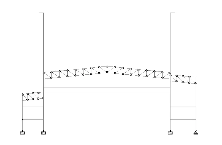
PROCEDURE OF MODELLING
- First the units for the load and the distance are setup as soon as the STAAD is opened
- The co-ordinates are added in order to model the structure as per the given input data.
- The beams are connected from node to node to from a frame.
- The supports like fixed or the pinned are defined with the help of the support definition
- The end and the start moment for the bracings and the truss members are released so that they take up only the axial forces
- The member properties are assigned to the beams defined.
- The dead and the live load that are acting on the structure are added by defining the dead and the live load cases
- The wind load and the earthquake load are defined are shown below
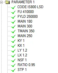
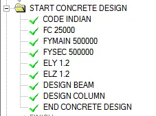
- Then the design parameters for the steel as well as concrete member are defined
- Then the structure is analysed and then checked for any failure members
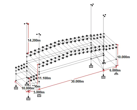
Section view of the model
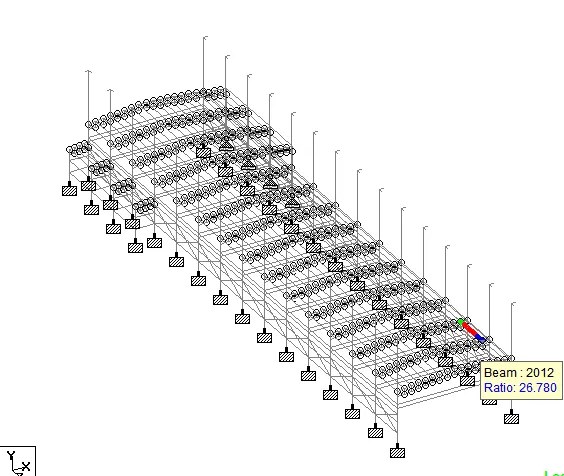
3D view of the entire structure
Section view of one bay
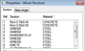
Defining of the member property and support
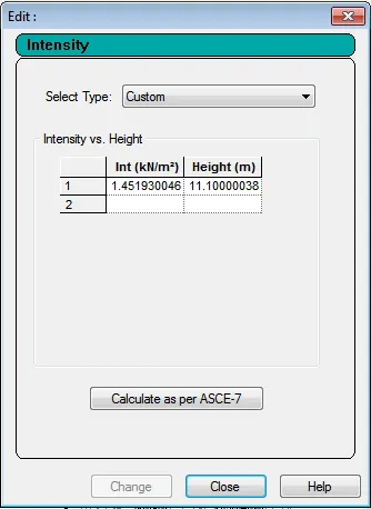
Load calculation
- The wind load is calculated as follows:
As per the question the project is located in at the wind speed of 180kmph thus the basic wind speed (Vb) is 50m/s
Total length of the industrial building for area 1 is 140m, width of the building for area 1 is 30m and the height of the building for area 1 is 11.1m.
Risk factor k1 = 1 (it is designed for 50 year life span of the structure) (from table 1 of IS 875 part 3)
The terrain category in this project is category 3. Therefore K2 for 7m height = 0.94(from table 2 of OS 875 part 3)
K3 the topography factor as per IS code is 1
K4, the cyclone factor = 1.15
Design wind speed (Vz) = Vb*k1*K2*k3*k4
= 50*1*0.94*1*1.15
= 54.05m/s
Design wind intensity (Pz) = 0.6*(Vz^2)
=0.6*54.05^2
=1752.84N/m^2 = 1.75kN/m^2
Wind load calculation with the internal pressure and succession are as follows
WL+X+CIP = 1.75*11.1+0.5-0.9 = 19.025kN/m
WL-X-CIP = 1.75*11.1-0.5-0.9 = 18.025kN/m
WL+Z+CIP = 1.75*11.1+0.5-0.8 = 19.125kN/m
WL+Z-CIP = 1.75*11.1-0.5-0.8 = 18.125kN/m
DEFINING OF EARTHQUAKE
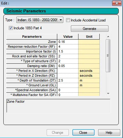
Earthquake parameters
Dehradun is located in zone III and the zone factor is 0.16
Importance factor = 1.5
Reduction factor = 4
Calculation of wall load upto 2.8m height = 0.23*21*2.8 = 13.524kN/m
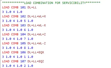
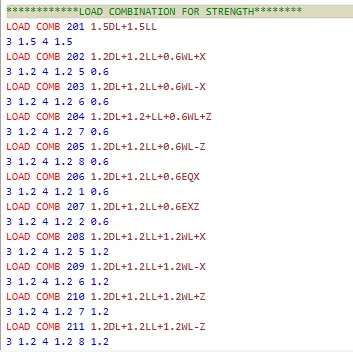
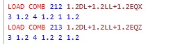
THE LOAD COMBINATIONS AS PER THE IS CODE CONSIDERED ARE AS FOLLOWS
LOAD COMBINATION FOR SERVICIBILITY
- DL+ LL
- DL+ LL+WL+X
- DL+ LL+WL-X
- DL+ LL+WL+Z
- DL+ LL+WL-Z
- DL+ LL+EQX
- DL+ LL+EQZ
LOAD COMBINATION FOR STRENGTH
- 1.5DL+ 1.5LL
- 1.2 DL +1.2LL+0.6WL+X
- 1.2 DL +1.2LL+0.6WL-X
- 1.2 DL+1.2LL+0.6WL+Z
- 1.2 DL+1.2LL+0.6WL-Z
- 1.2 DL+1.2LL+1.2WL+X
- 1.2 DL+1.2LL+1.2WL-X
- 1.2 DL+1.2LL+1.2WL+Z
- 1.2 DL+1.2LL+1.2WL-Z
- 1.2 DL+1.2LL+0.6EQX
- 1.2 DL +1.2LL+0.6EQZ
- 1.2 DL+1.2LL+1.2EQX
- 1.2 DL+1.2LL+1.2EQZ
- 0.9 DL +1.5WL+X
- 0.9 DL +1.5WL-X
- 0.9 DL+1.5WL+Z
- 0.9 DL+1.5WL-Z
- Design parameters for steel structure
- Design parameters for concrete structre
Conclusion:
From the project carried out it can be concluded that the concept of the design procedure of the industrial building of a coil centre is learnt and the various loads that acts on the building during the lifetime of the structure is considered for the design of the building and the reasons for the failure of the same is learnt. The method for the determination of the size of the building components are learnt and the calculation of the lateral forces like wind load and the seismic force is also learnt. The design parameters that are to be considered while designing the steel and concrete structure is learnt.