Project 1
V 16 ENGINE WIRING HARNESS
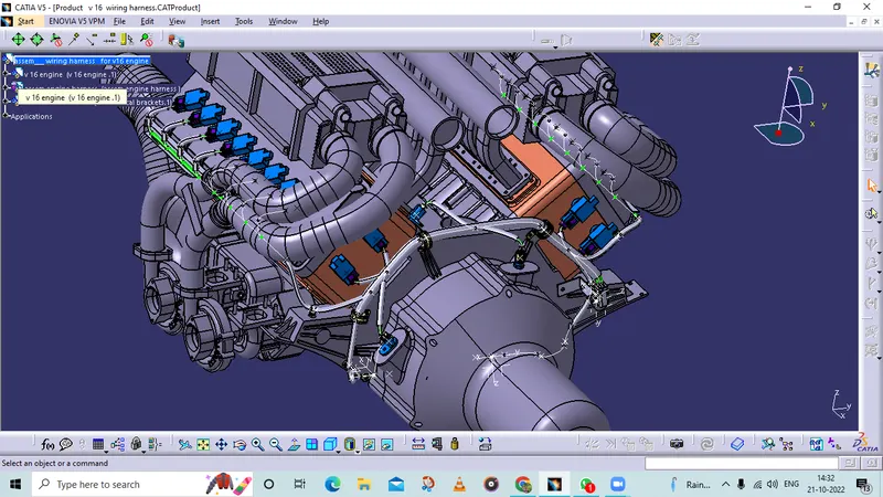
- To design and develop the Wire Harness Routing for the given V16 Engine by following the design and packaging rules.
OBJECTIVE:
- To define all the connectors electrically and save it in the Catalogue.
- To place all the connectors and cavities at the required position.
- To place P Clamps and Fir Tree clips at the required position by following the packaging rules.
- To create the Wire Harness Routing as per required and create branch points wherever required and also by following the packaging rules.
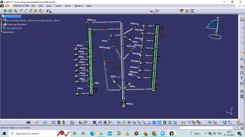
- To create the Wire Harness Flattening of the above routing.
- To display the flattened view in the drawing sheet.
DESIGN METHODOLOGY:
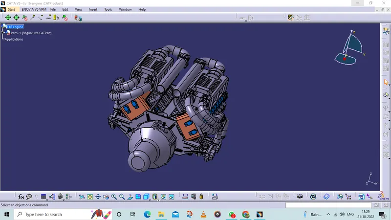
ADD THE GIVEN ENGINE FILE - STEP FILE - PRODUCT FILE
AM CREATED A PRODUCT FILE FOR THE V 16 ENGINE
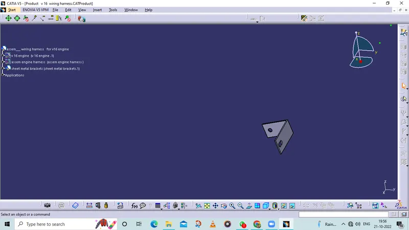
sheem metal bracket is added to act as a suport in v 16 engine to connectors
For the fixing in the connectors
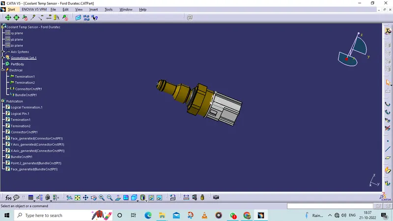
THE CONNECTORS, CLIPS, P CLAMPS, AND CHANNEL.
ARE DEFINED AS ELECTRICAL PARTS.
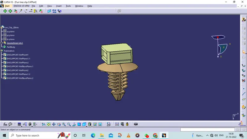
FURTI CLIP
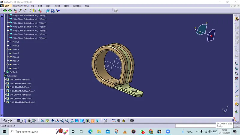
P CLAMP DEFINED AS A ELECTRICAL PART
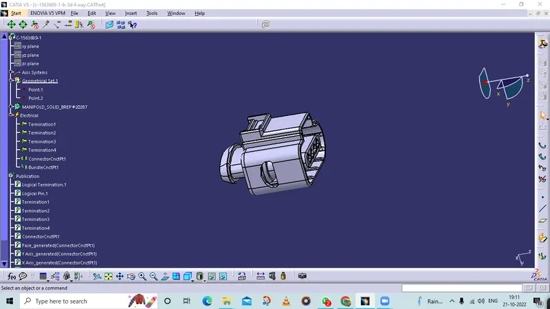
4 TERMINAL PIN CONNECTOR DEFINED AS A ELECTRICAL PART
2 PIN CONNECTOR DEFINED AS A ELECTRICAL PART
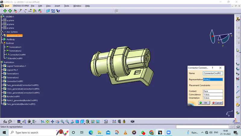
2 PIN CONNECTOR DEFINED AS A ELECTRICAL PART
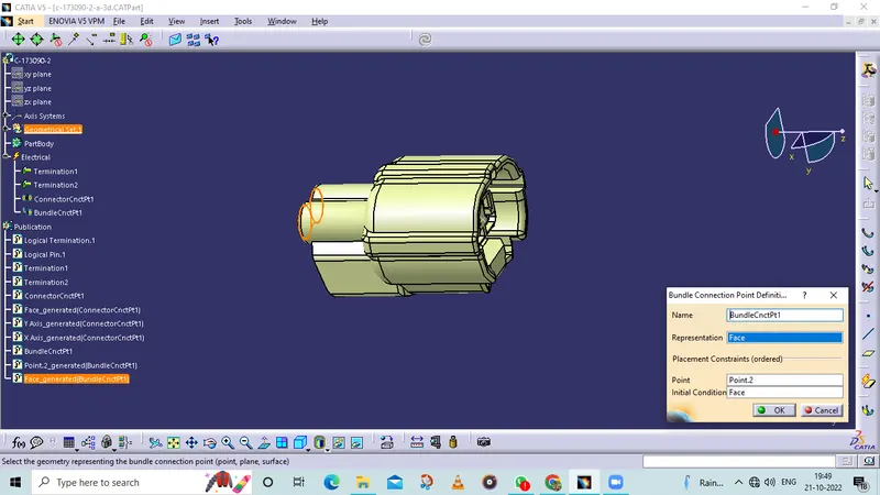
12 PIN CONNECTOR DEFINED AS A ELECTRICAL PART
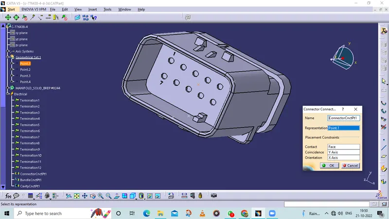
channel 1 defined as a mounting equipment
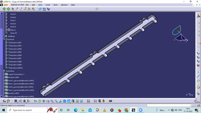
channel 2 defined as a mounting equipment
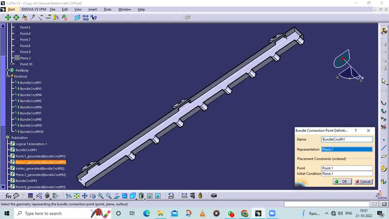
PROTECTION ADDED FOR BUNDELS COT TUBE ADDED
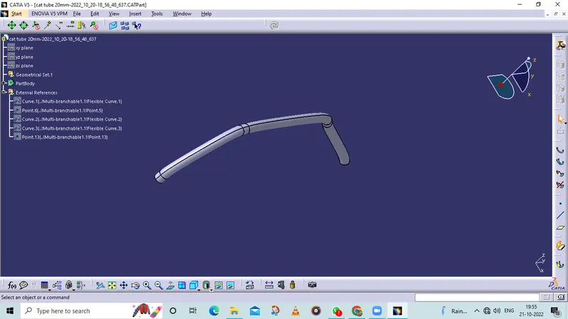
In below figure, have added 15mm slit COT tubes on top of the bundle segments as a protective covering.
We have assumed start and end extremity for the COT tubes approximately
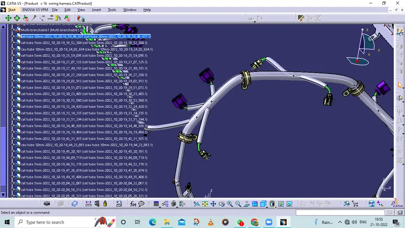
MULTIBRANCH ADDED IN TO THE ELECTRICAL HARNESS ASSEMBLY.
MULTI BRANCHBLE
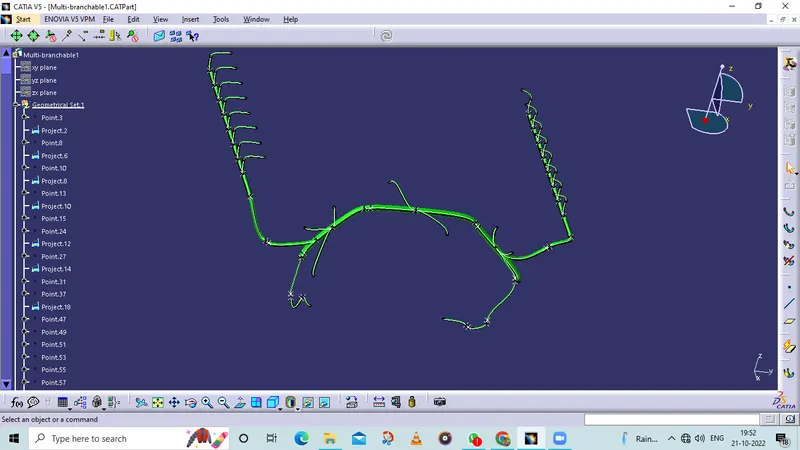
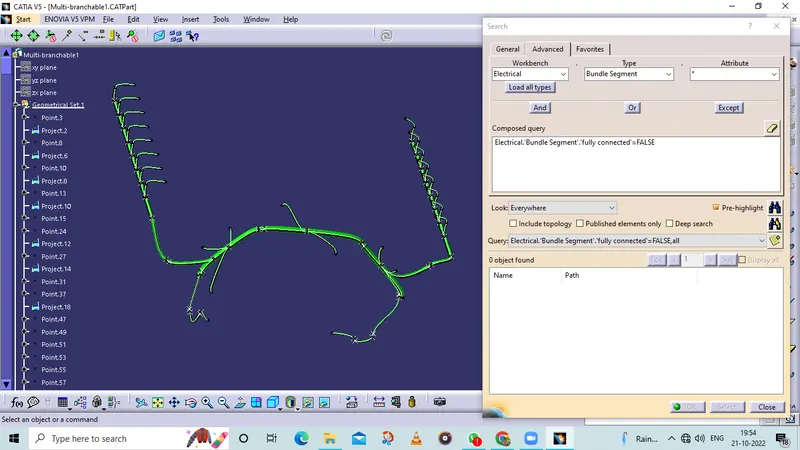
CONNNECTIVITY CHECK FOR ELECTRICAL BUNDELS
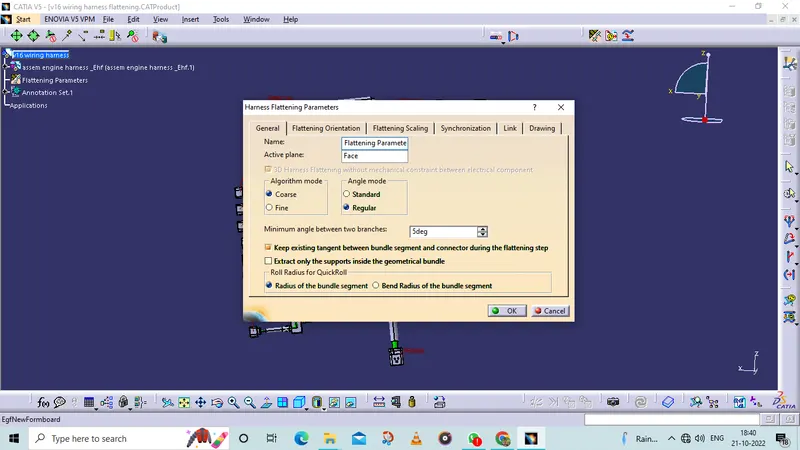
DEFINED FATTENING PARAMETERS
EXTRACTED FROM ELECTRICAL HARNESS ASSEMBLE TO TO FLATTENING