Project 1
MOLD DESIGN FOR TABLE FAN BASE
OBJECTIVE:
To create a complete mold for a table fan base.
MOLD:
Molding or Moldmaking is the act of creating the cavity / form that carries a negative or reverse impression of an original model. ... The solidified part is also known as a casting, which is ejected or broken out of the mold to complete the process.
INJECTION MOLDING:
The injection molding process involves heating & injecting plastic material under pressure into a closed metal mold tool. The molten plastic cools & hardens into the shape inside the mold tool, which then opens to allow the moldings to be ejected or removed for inspection, delivery, or secondary operations.
Injection molding is a manufacturing process that allows for parts to be produced in large volumes. It works by injecting molten materials into a mold. It is typically used as a mass production process to manufacture thousands of identical items. Injection molding materials include metals, glasses, elastomers, and confections, although it is most commonly used with thermoplastic and thermosetting polymers.
SCALE:
After the part is comes out of the mold blocks the due to cooling the part starts to shrink , the shrinkage is based on the material used.For ABS material the shrinkage value is 6%
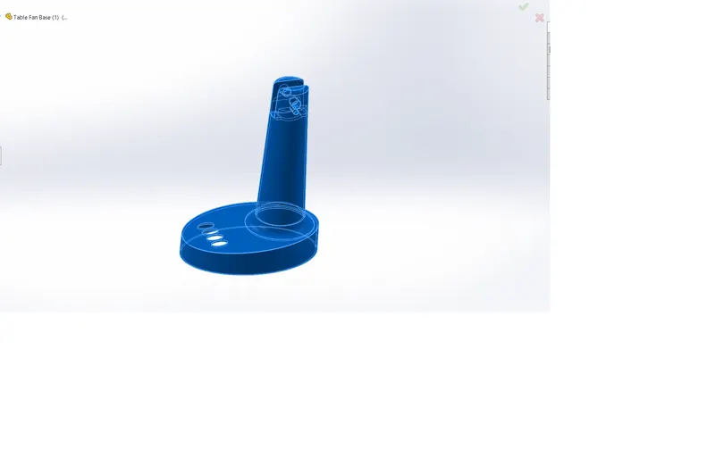
PARTS OF MOLD:
- CORE
- CAVITY
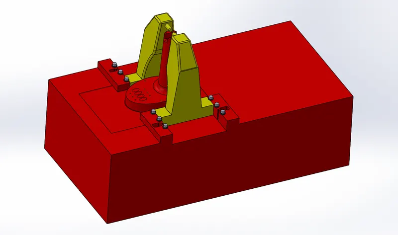
- SLIDER
- INSERTS
- EJECTOR PINS
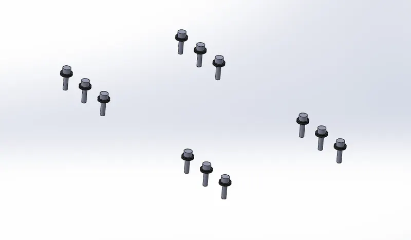
- WASHERS AND BOLTS
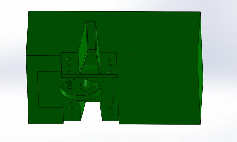
CORE:
Core is the movable part , when the molten material is poured into the sprue it flows through the runner and travelled to the cavity between core and cavity part and gets solidified.
The solidified part stick , the solidified part should be ejected for that ejector pin are used .The ejector pins are present on the core side which pushes the solid part out of the core body.
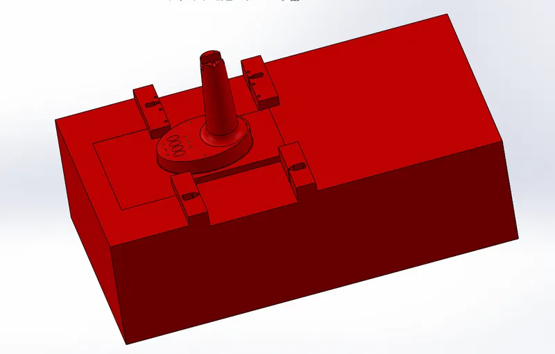
CAVITY:
Cavity is the fixed part , sleeve , gate and runner are present in the cavity side only. Drafts must be given to the cavity side so that the solidified part doestn't stick on the cavity side.If the draft is not provided on the cavity side, the the solidified part stick to the cavity side which is dificult to remove the slodified partbecause cavity side doesn't have ejector pin to eject the casted part out.
SLIDER:
Undercuts are those features in injection molded parts which prevents its ejection from the mold.
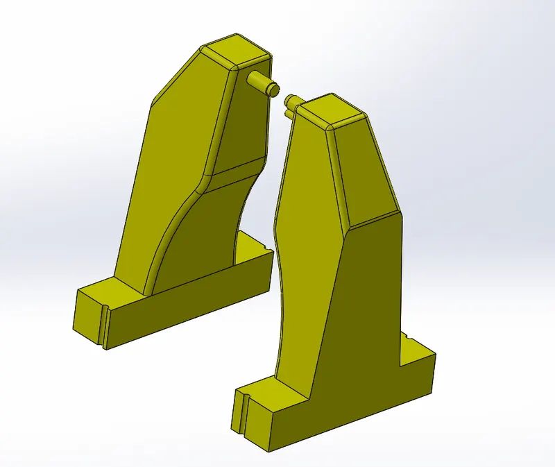
In the table fan outter casing model there are two holes forming the undercuts.This prevents the removal of the part form the mold towards the direction of tooling.
To solve this we create slliders.Sliders are seperate parts which can be slide out of the mold before the part is removed thus preventing the formation of undercuts in the molds.
EJECTOR PINS:
Ejector pins are circular rod like structures that are used to eject the parts out of the core body.the ejector pins are usually located in the indepth cut featurs like ribs.

Ejector pins comes in standard diameters of 1mm,3mm,and 6mm.Like said before the ejector pins are located on the core side of the mold blocks to eject the casted part out of the core body.
WASHERS AND BOLTS:
Washers and bolts are used to hold the sliders in rigid position .Because the molten material folws at high pressure, to resist that high pressure the bolts and washers are used to tighten the slider parts.
TOOLS USED:
- SKETCH
- REFERENCE PLANE
- DRAFT ANALYSIS
- SCALE
- PARTING LINE
- SHUTOFF SURFACES
- EXTRUDED BOSS/BASE
- CUT WITH SURFACES
- EXTRUDE CUT
- MOVE FACE
- COPY/MOVE BODY
- SPLIT
- DELETE/KEEP BODY
- COMBINE
- SKETCH DRIVEN PATTERN
- CORE
DESIGN PROCEDURE:
STEP-1:DRAFT ANALYSIS
First the given part is check for any undercuts and drafts provided.
STEP-2:SCALE
Assume the material for the table fan base is ABS and the shrinkage value for the ABS material is 6%.SO scale the part to 1.006 times the original value.
STEP-3:PARTING LINE
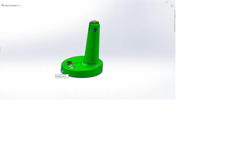
Now we need to seperate the mold into core and cavity.For that parting line command is used which seprates the core and cavity surfaces.
STEP-4:SHUT OFF SURFACES
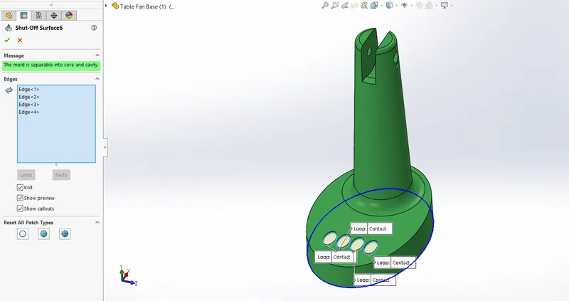
Parting line only not sufficient to seperate the core and cavity surfaces if there is any holes are present in the givven model.To close those holes shutoff surfces command is used to close those holes.
Now the mold is seperated from core and cavity.
STEP-5:EXTRUDED BOSS
After the surfaces are created , sketch is drawn to create solid core and cavity blocks using extruded boss command.
STEP-6:CUT WITH SURFACE
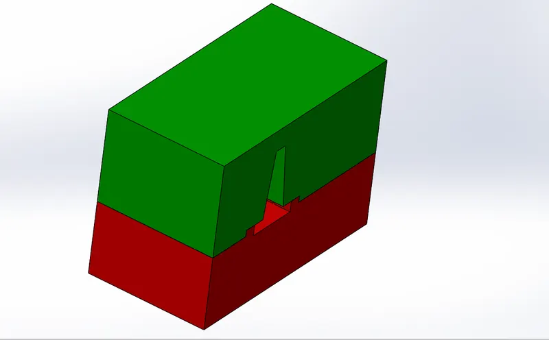
This command is used to cut the solid block with the surface that we created and now the mold got its shape.Assagin green color to the cavity block and red color to the core block.
STEP-7:SPLIT
Split command is used to split the mold block .Create a sketch and a plane and perform the split option then select the the part that need to be splited.slider is created using the split command insert the created slider into new part .
STEP-8:COMBINE
COMBINE option is used to subract the slider from the core model.By doing this we get the cavity space in the shape of slider for slider to move freely.After inserting the slidder as seperate part file now created an another part file for washers and bolts.
STEP-9:HOLE WIZARD
After the washers are created , a hole must be provided on the core block for proprer alignmet of the bolts with the core block.To create the holes hole wizard is helpfull to create the requied holes on the care block.
Metric M6 tapped hole is selected from the hole wizard.
STEP-10:CORE
CORE command is used to create the ejector pins on the core mold block.For 3 mm pin the clearence for ejector pin is 3.95mm.
MOLD BLOCK IMAGES:
CONCLUSION:
Thus as per the objective I have created the mold blocks, ejector pins and sliders for the given table fan base.