Project 1
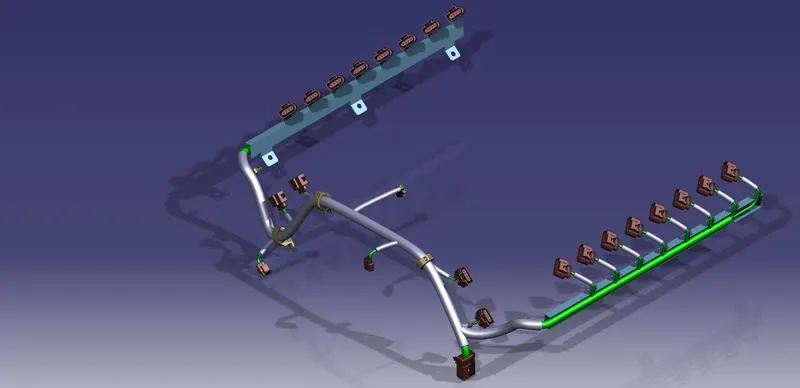
AIM: To Route the Wiring harness on Given Engine and Prepare flatten view drawing in CATIA V5. Application of all Packaging rules, Industry best practices studied in this course shall be demonstrated in design. Apply Protection coverings as required.
Analysing the given data.
The 3D model of the engine is downloaded from the link provided. The model is analysed for designing the Wiring Harness.
Connections
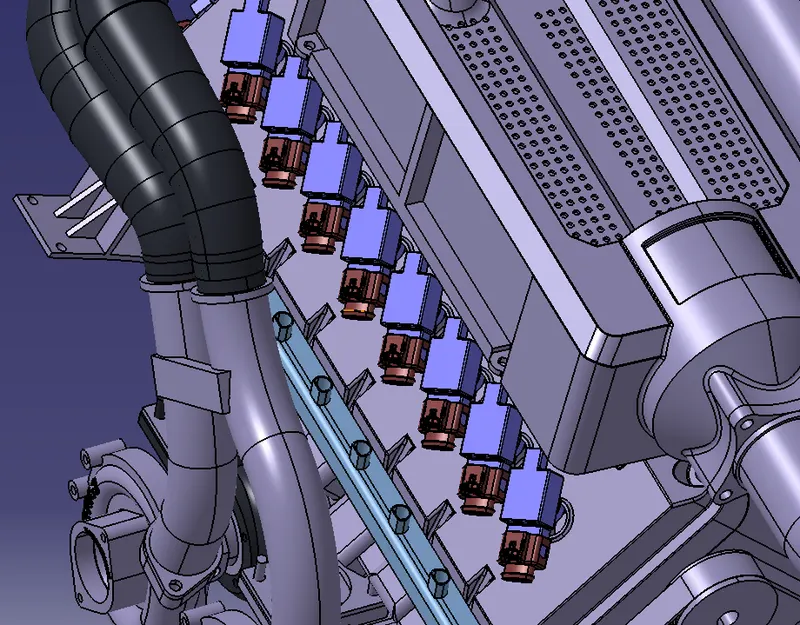
- The engine need connections for 16 Fuel Injectors of each cylinders. They are provided as 8 on each centre blocks. They need 4 pole connectors.
- It have 4 camshaft sensors given 2 on each center blocks. They also needs 4 pole connectors to connect to the bundle.
- Engine coolant sensor is given between the 2 center blocks. It require a 3 pole connector
- There are two sensors on the engine transmission assembly. One need a 2 pole connector and the other require a 3 pole connector.
- A 12 pole interconnection connector will be required to take out the complete connections from the engine harness assembly.
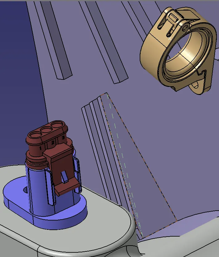
P clamps can be mounted on to the screw holes on the transmission assembly covering to route the wiring harness along the different sensors.
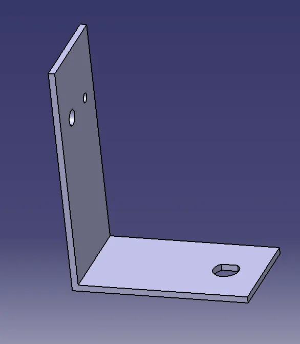
An anti rotational metal plate will be required to mount the interconnection connector on to the engine.
Electrical Component Selection
Connectors
C-1718562-1: It is a 4 pole sealed connector. It can be used for connecting to the fuel injectors and to the camshaft sensors.
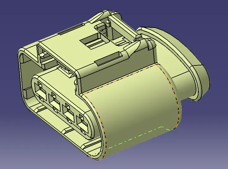
C-282087-1 : It is 3 pole sealed connector. It can be used for the temperature sensor and the transmission sensor.
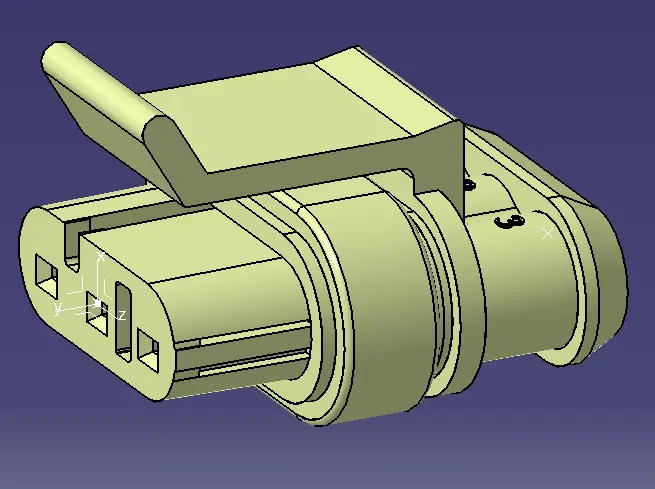
C-173090-1 : It is a 2 pole sealed sensor that can be used for one of the transmission sensors.
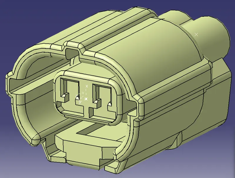
C-776438-4 : It is a 12 pole wire to wire connector that can be used as the interconnection connector in the in the harness assembly. It have cavity connection feature to aid the possitive mounting of the connector.
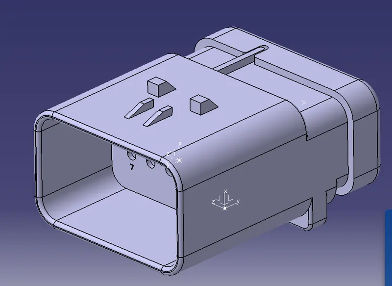
The connector are selected considering the size, no. of poles, operating conditions, connection type and mounting strategy.
Clips and Clamps
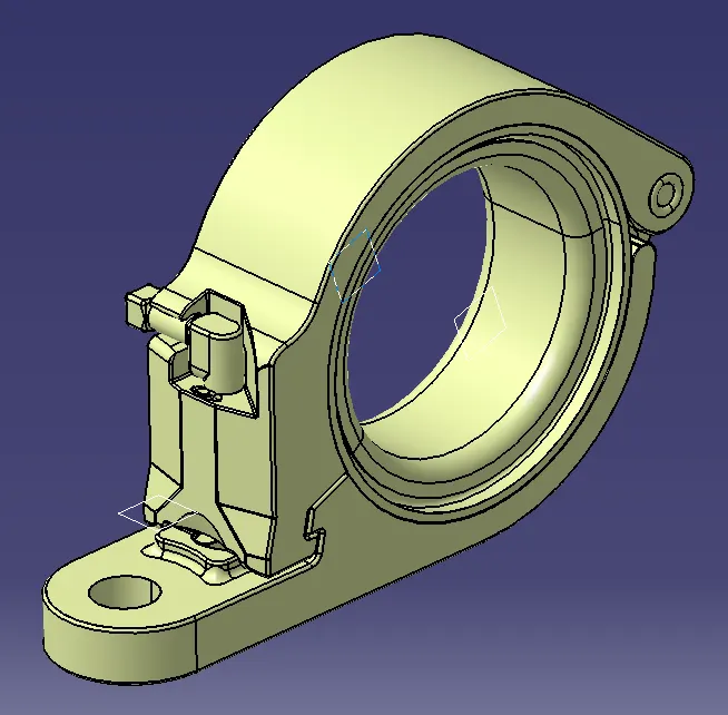
P-clamps and Fir tree clips are used to route the bundle along the engine parts.
P-Clamps :
Fir Tree Clip:
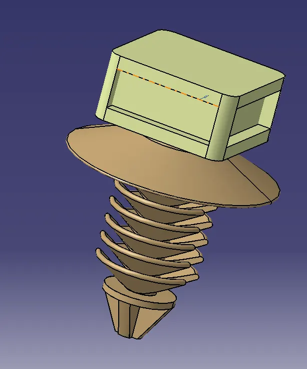
Connector Mounting Fir tree Clip (C-1924487-2): It is used to mount the interconnection connector on to the L shaped metal plate. It is an anti rotational clip.
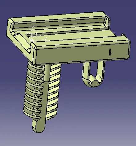
L-Shaped metal plate:
Channels:
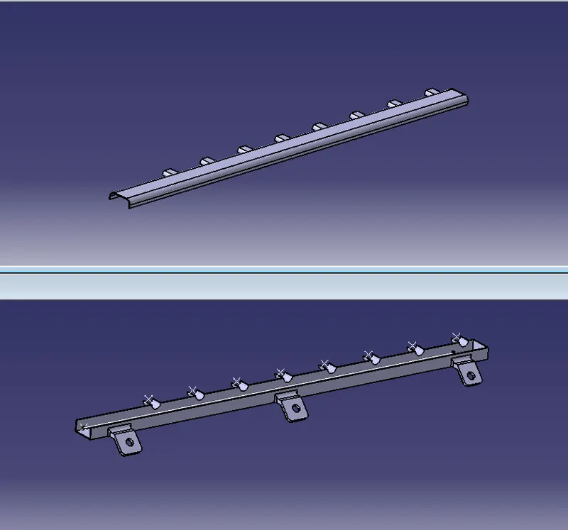
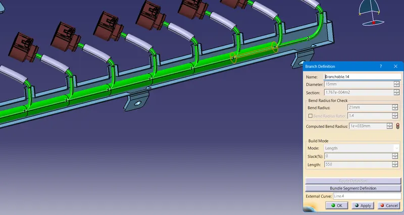
A channel is designed to distribute wire to the injectors. 9 bundle entry ways are given to the channels. It is designed as two parts bottom and top. Two symmetrical channels are designed for two centre blocks.
Catalogue Creation
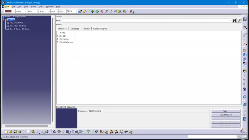
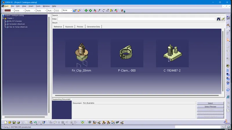
A new CatalogueDocument is created. Two families of COT Tubes(Conduit type),Clips & Clamps and connectors(electrical type) are defined.
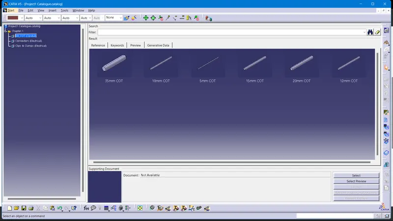
The COT tubes of required dimensions are created in the electrical part design workbench and are added to the COT family of the catalogue.
Electrically defining the components
Referance points and axis system are created which are necessary for defining the connector connection point and bundle connection point of the connector. In the Electrical part design workbench, the parts are defined as electrical connectors. The connector connection point and bundle connection point of the connector are defined with the help of previously defined points and axis systems. The connectors are added to the catalogue in the connector family.
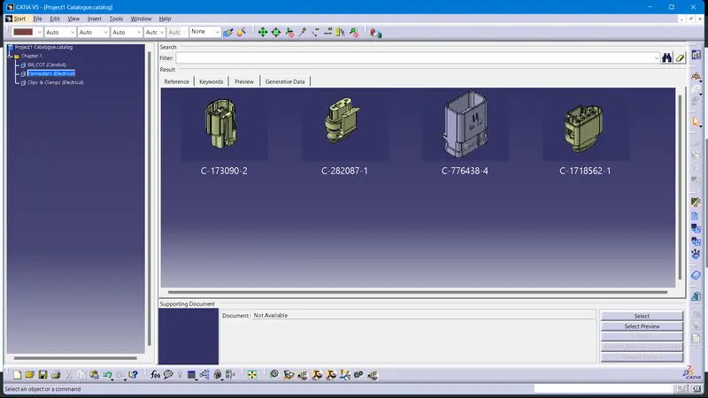
The connector mounting clip is defined as mounting equipment in the Electrical part design workbench. And cavity is defined for the equipment with predefined axis systems and points.
For the P-clamp and Fir tree clip the necesasry planes and points are defined. It is defined as support part using the planes and points in the Electrical part design workbench.
Clips and Clamps are also added to catalogue
The above mentioned channel is defined as the Electrical equipment and different bundle entry points are defined.
Creating the Product file
A new product file named 'Engine_Harness_Context' is created. A product file named 'Engine_Harness_Geometrical_Bundle' is added to the product file. All the connectors which are electrically defined are inserted to 'Engine_Harness_Geometrical_Bundle' product. This product is electrically defined as Geometrical bundle in the Electrical Harness Assembly workbench. The downloaded Engine file and L-shaped metal plate is also inserted into the context assembly file.
Positioning the Components
The connector added into the geometrical bundle is positioned according to the various sensors in the Engine file.
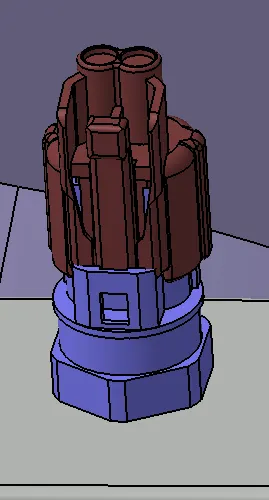
Wiring Harness Routing
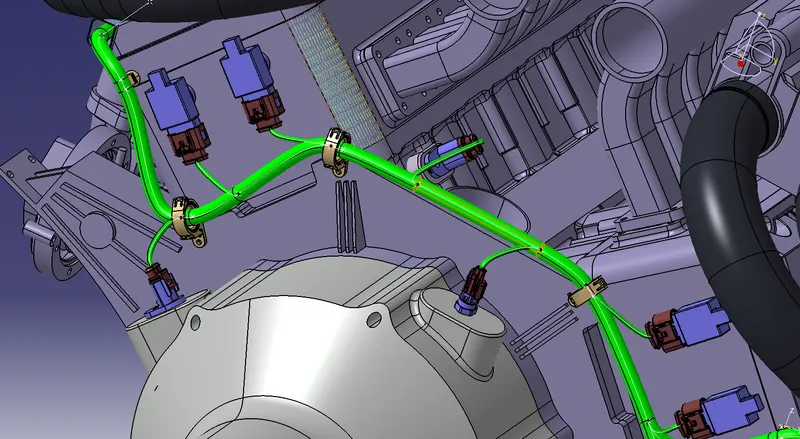
A multibranchable document is created in the geometrical bundle. The routing is done with the the different connectors and also with the help of P-Clamps and Fir Tree clips. The routing is completed following the industry best practices and rules. Slacks are given in the segments which are necessary. The main branch is given 15mm diameter, and 5mm to sub branches going to the connectors.
The wiring inside the channel is defined by using external curve.
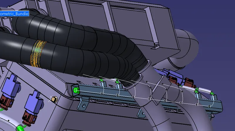
Currently in the input engine CAD data there are no provisions for fixing the guiding channel and the fir tree clips. They are placed on the center block. The possibility for this has to be discussed with the Engine design team before finalising the design.
Bundle Connectivity:
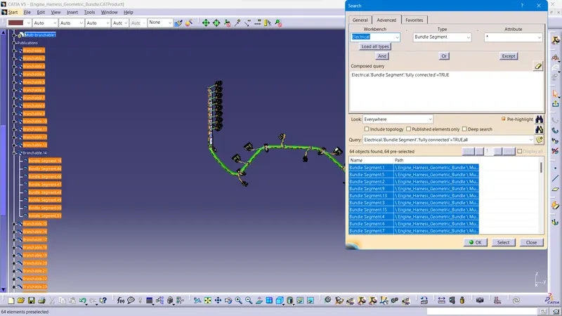
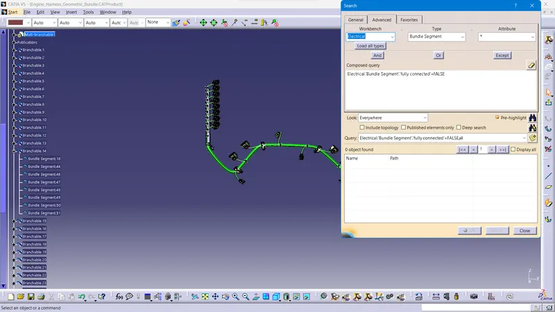
The bundle connectivity is checked using the search tool in the edit menu.
TRUE
FALSE
Adding Protective Covering
In the Electrical Harness Assembly Worlbench, using the 'Protective Covering' tool, the cot tube is added to different bundle segments according to the bundle diameter.
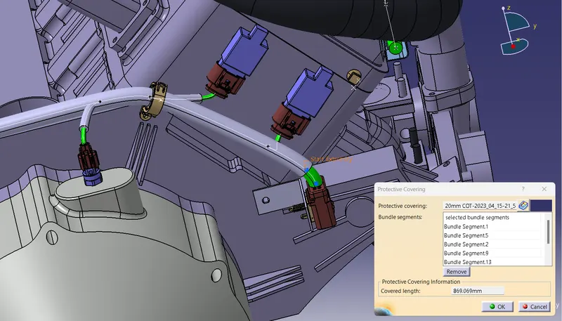
And appropriate gap is provided for the covering from the connectors.
Electrical Harness Flattening & Drawing
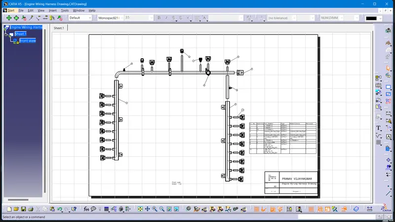
A new product file for Electrical Harness flattening is created and opened in the Electrical Harness Flattening workbench. Harness Flattening parameters are defined. Then the Harness Assembly is extracted to the flattening product. Then it is flattened. Using different tools, the bundles are rotated and rolled.
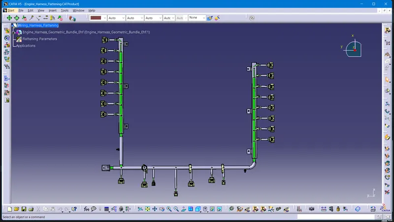
Then a drawing file created with the flattened assembly product file. The Title frame and Bill of materials are added to the drawing.The components are marked with balloons with reference to teh BOM. The drawing is also converted into .pdf format for the ease of sharing.
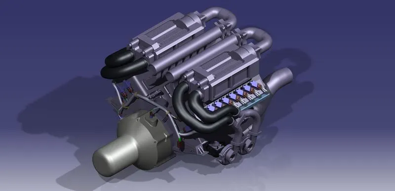
Rendered Images of Final Product:
With the referance Engine Environment
Geometric Bundle Alone