Week 8 - Challenge 2 - Switch Bezel Design
Class A Draft analysis
First considering the direction of the holes on the class a surface, the z axis is selected as the tooling direction. The axis is supposed to pass through the point at the centre of the base surface of the class A surface. Then the intersect of the class A surface and zy plane is taken. From that the bisecting line of the, intersect lines which is near to parellell to z axis is taken as line1. Then the intersect of the class A surface and zx plane is taken. From that since there is only one surface, a line passing through the above point and an angle of 5 digree to the surface is selected. Because giving 3 digrees is causing less angle to the final tooling axis in draft analysis. This line is considered as line 2. Then a line bisecting line1 and line2 is constructed. This line is selected as the tooling axis .
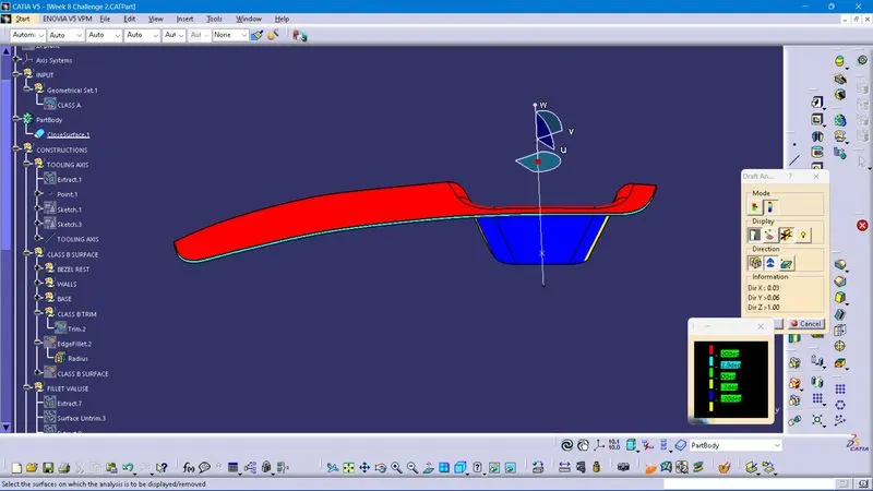
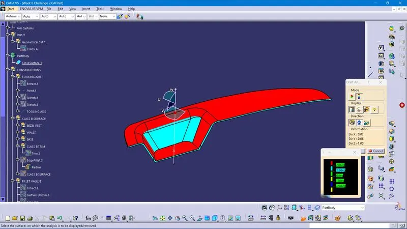
Using the above selected tooling axis, the draft analysis of class A surface is performed. Analysis result shows that all the surfaces have fairly much larger angle than 3 digree which is the nominal draft angle. The screenshots of the analysis result is given below
Final Part draft analysis
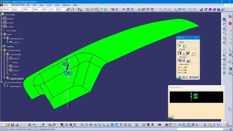
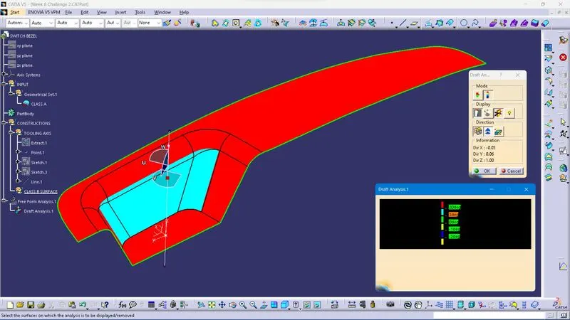
The draft analysis is conducted on the final part with tooling axis as reference. Very negligible areas of the class C surfaces is below 3digree but all the surfaces are greater than 2.9 digree which is a allowable draft angle. So the part is manufacturable. The screenshots of the analysis result is given below.
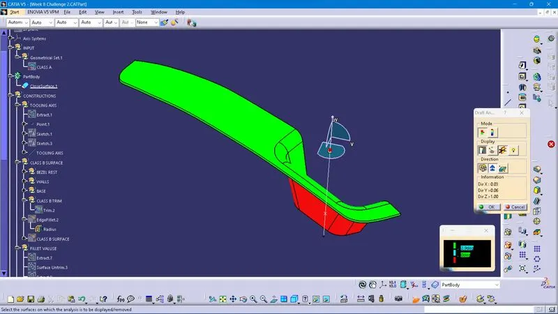
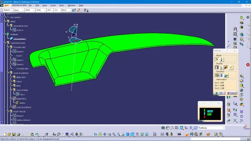
Screenshots of the part with color code of the draft angle