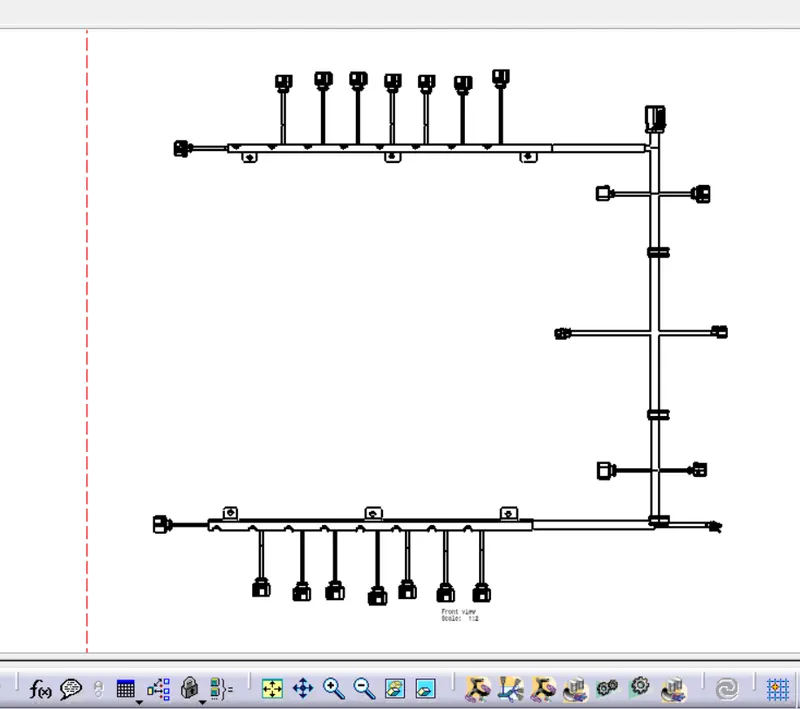
Project 1
- CLEARANCE MANAGEMENT:
Clearance managementbasically focussed on the wiring harness clearance with the surrounding parts. This is primary requirement for the routing and packaging.
This study is a part of geometrical integration.
Clearance requirement varies between industry to industry. how ever following requirements can be used to understand th basics of clearance management.
Wiring harness to STATIC PARTS- 10mm, to dynamic parts-25mm, to sharp edge-10mm, To fueline, brake line, hydraulic line-50mm, exhaust manifold & component-200mm, heat source (unsheilded)-200mm, heat source sheilded-50 mm etc.
- Clipping/Clamping selection:
Clips are used to route the harness and for harness clamping in each area.
Different types of clips:
- Fir tree mount and cable tie assambly: the mount can slides along the strap of the tie for proper orientation
- High temperature fir treee mount cable: it provides exccelent resistance in operating temparature upto 270degree
- Fir tree nount tube clip: this tube clips allow the installer to provide the force on it to fit the bundle with it
- C clip with fir tree mount: this allows for easy insertion of clip into a parallel drilled hole
- Cable tie mount: desidned to provide stability to wire bundle
- Dual clamps ties: it is designes to provide parallel seperation between hoses, wire , cables and tubing.
- Dual swivel: these mount can be easy rotated by hand saddles spacers are used to prevent chaffing and wear
- Harness fixing requirements:
- Wiring harness should be routed in such a way that it is easy to assamble on vehicle.
- wiring harness topology plays an importatnt role to meet this critaria
- wiring harness shoud be routed that it would be easy access in service and faluire analysis
- Distance between two clamps on a straight branch should be minimum of 200mm.
- The minimum branch length should be 50mm.
- Minimum distance between clip and nearest branching point should be 25mm.
- The minimum distance between two straight connection points should be 200mm.
- The minimum distance between two breakout points should be 50mm.
- To limit the number of branches from a single branch point to 4.
- Avoid routing wiring harness near the exhaust manifold and its components and also from other unshielded heat sources. If re routing is not possible then maintain a minimum distance of 200mm.
ELECTRICAL DEFINATION AND CATALOG REATION:
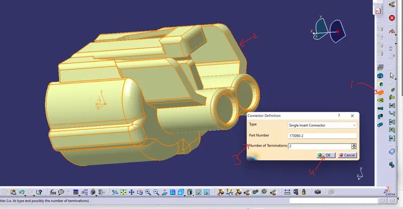
FIRST OF ALL open the commector and create switch to part workbench and create connector connection point, bondle connection point, connector connection axis system, and cavity connection point and axis system when needed and switch to electrical part design and go to CONNECTOR DEFINITION>SLELCT CONNECTOR > GIVE THE BUNDLE CIRCUITE POINT> OK as shown in below image
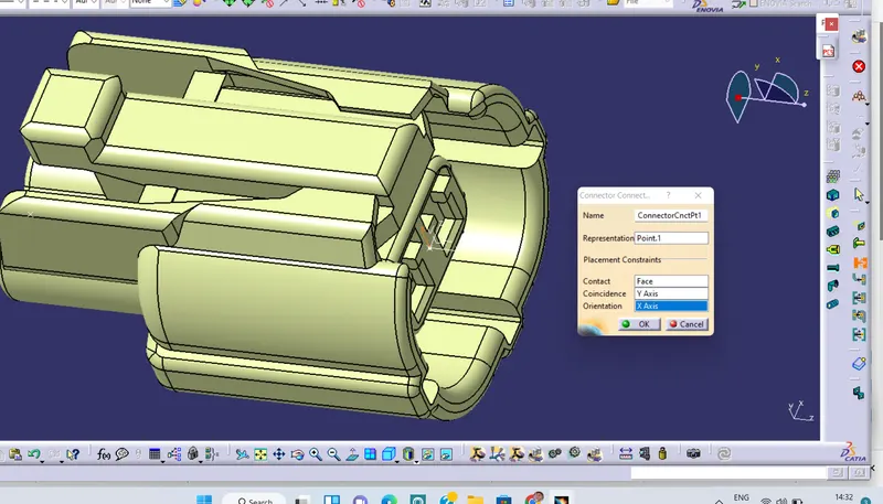
Now click on Connector connection point >click on part>and give the necessary as shown in the below image
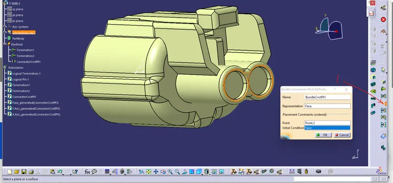
Now click on BUNDLE CONNECTION POINT>part>give the necessary as shown in the below images
Now here our connector is fully electrical defined now we will add it to the cataloge for this go to the STORE DEVICES>select the file location>select family as a connector >ok see below image
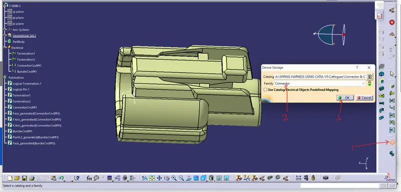
our conncor is added to the catalog.
Similarly we will follow the same process as discussed above to defined the different connector electrically and than after adding them into the catalog. insome cases there would be need to defined cavity connection point to connect the different mounting with the connector.
ROUTING OF BUNDLE:
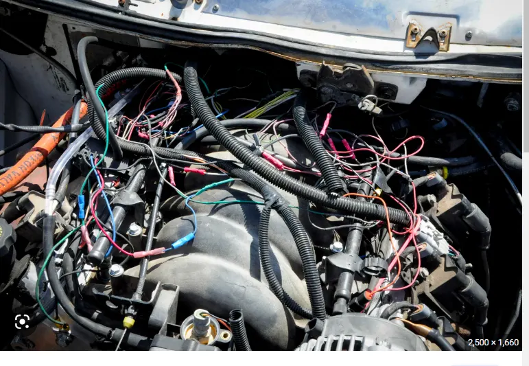
An engine wiring harness is an organized set of wires, cables, connectors and terminals that controls a vehicle’s electrical system.Hraness Manages the key functions around the engine including engine controller, oil controller gate, transmission plug housing, air pipe sensors, pressure sensors, and water temperature sensors.
First i have downloaded the v16 engine surface here the connectors are placed for various functioning on the engine like Fuel injector, cam shaft sensor,temparature sensor, transmission plug housing etc.
these connectors are of sam colour we will first differ these connector colour withe engine colour so that it is easy for the roting and the connector placement.
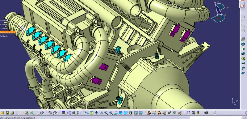
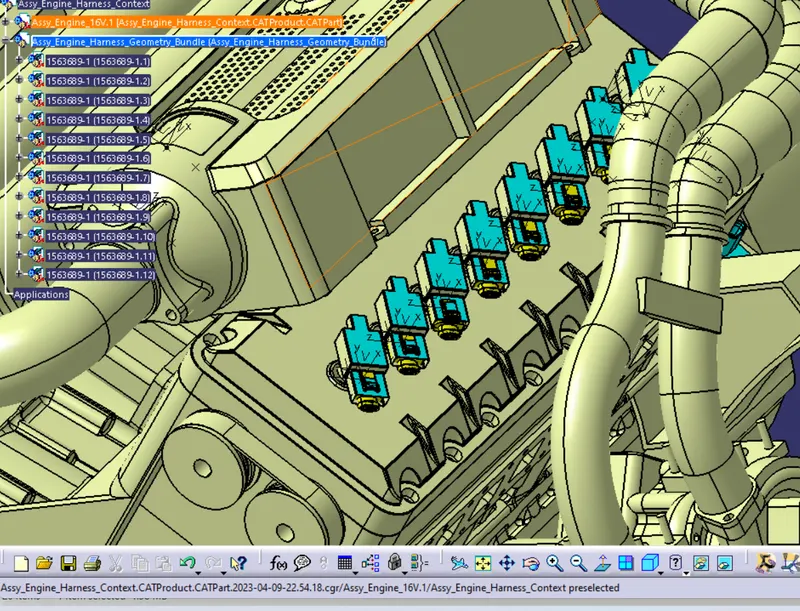
Now we will placed the connectos at the injector system housing withe the help of manipulation and smart move command and also place this connector to the cam shaft sensor housing as shown below image
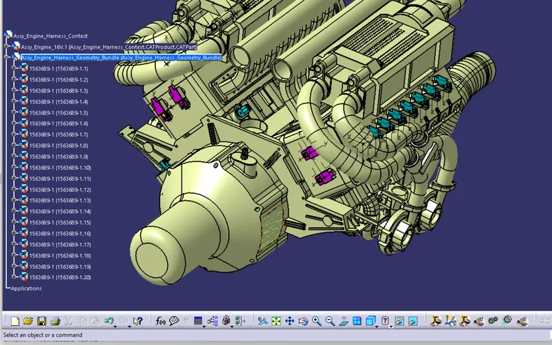
and for temperature sensor and transmission plug housing we will place different connectors as shown in below image
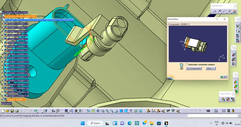
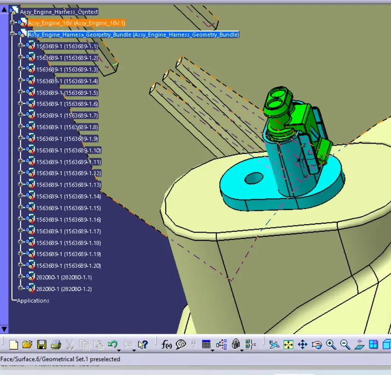
Now we will insert a l type clip and here we willl mount the the connectors for external wiring harness from chasis as shown in below image
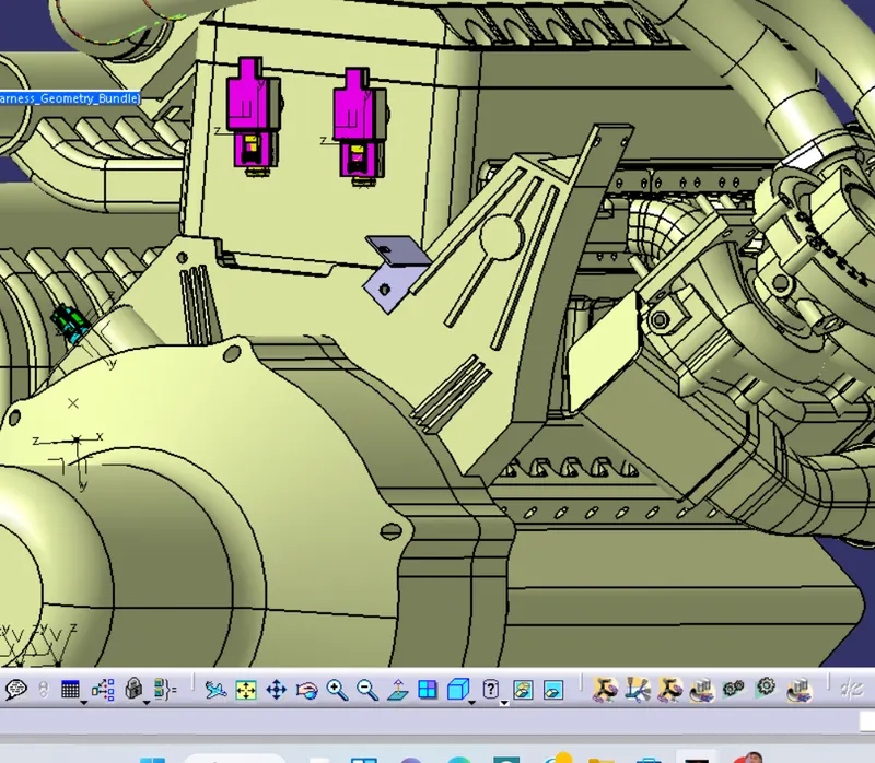
now we will also insert a plastic channel for the proper routing of the bundle at the injector side image1 amd we will defined the channel electrically as shown in the below images
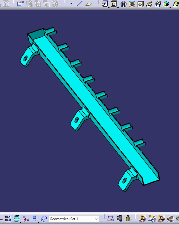
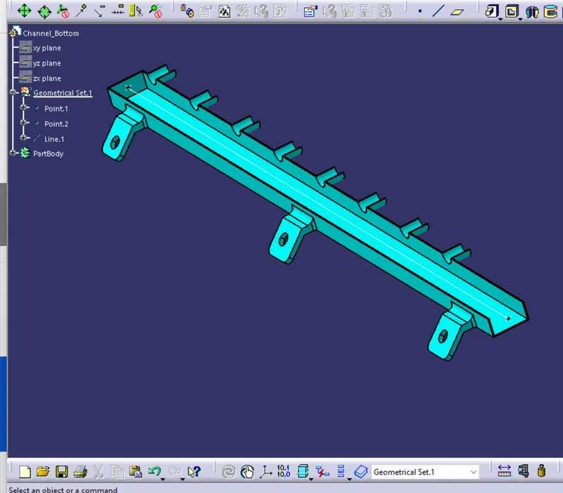
fIRST WE will create a point and a straight line now switch to the electrical part design and defined component as shown in below image
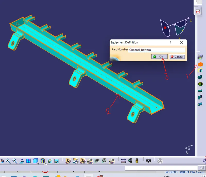
Now defined the entry point and the 8 circular slot as bundle entry point as shown in below image
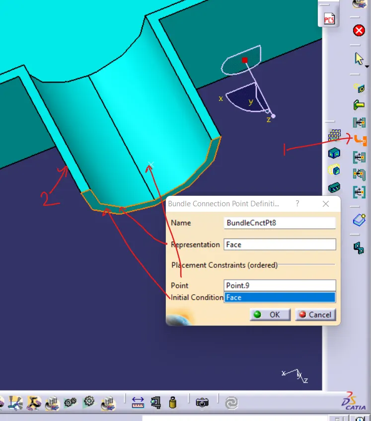
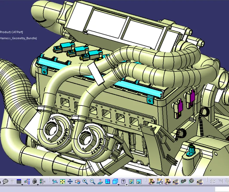
Bundle creation:
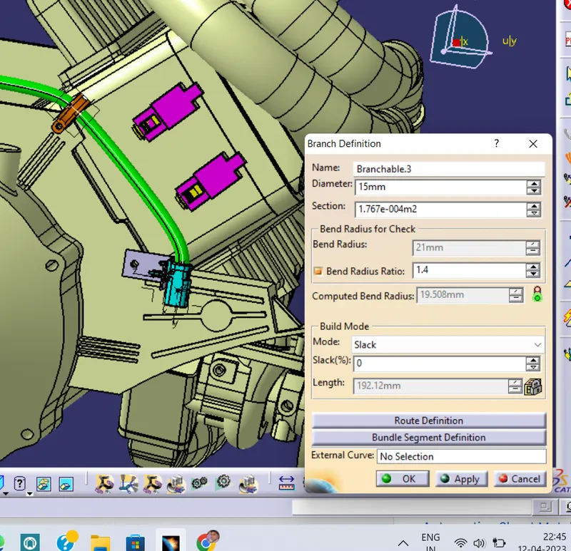
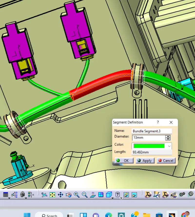
we will switch to the ELECTRICAL HARNESS ASSAMBLY >BRANCH DFINITION>keep the diameter as 15mm and >ROUTE DEFINITION>select the connector and P clamp see below image1. now after it we will be creating a branch point >Go to branch point >click on bundle >and select a point where we want to be branch see image2
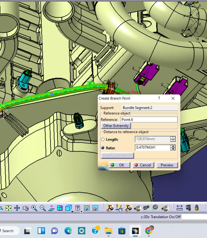
Here the diameter of the bundle is getting reduce because at the branch point there is an wire cones out from the main bundle
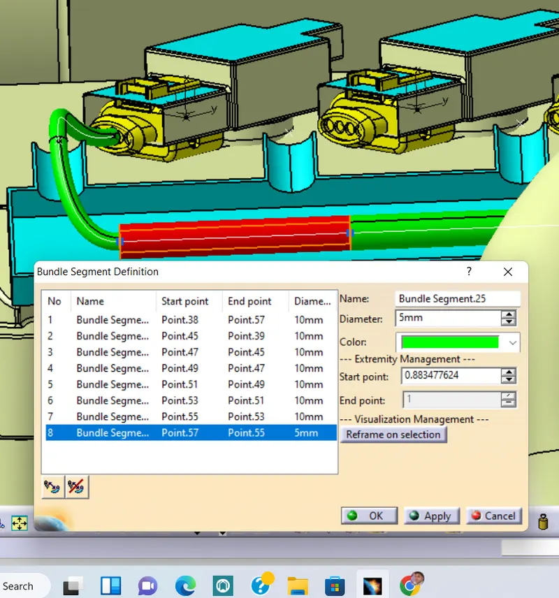
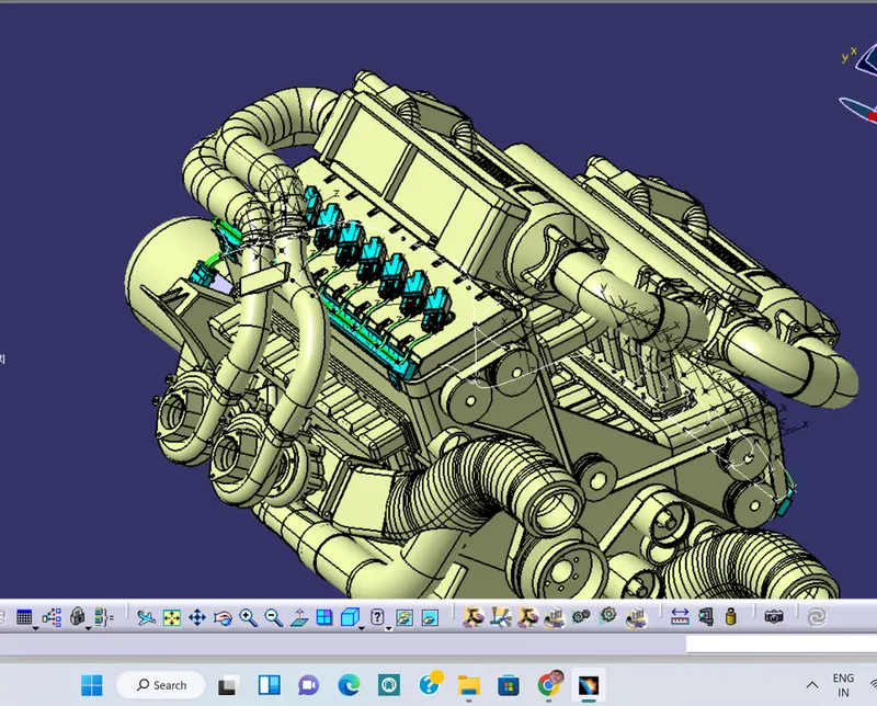
final routed engine is shown in below image
FLATTENING:
Here we will do flatten the geometrical bundle for this open the Geometrical bundle in new window
go to file>new>product>named it as a flatten harness and save switch to Flattening work bench
Now go to FLATTENING PARAMETER>AND do all necssary settings.
now click on topof the model tree and goto command EXTRACT>SELECT THE bundle geometry , here our 3d bundle geometry will be added eith change in name as Ehf see below image
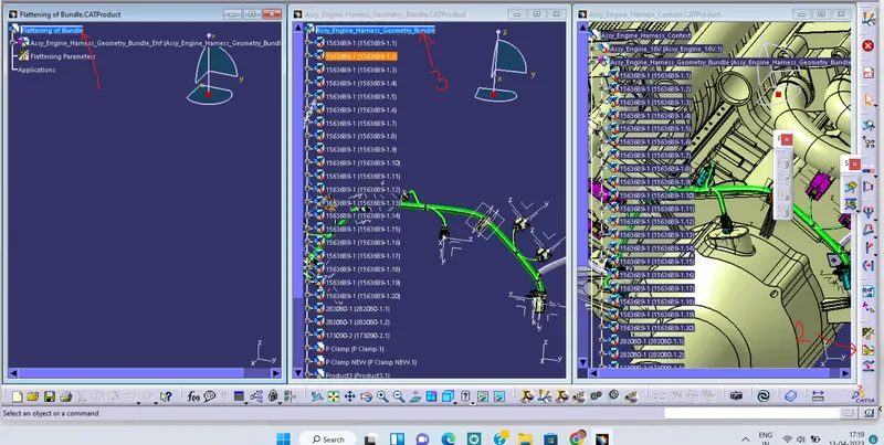
Now go to Flaatten >select plane>select branch>selectall>make sure that all the bundle are selected >ok rsult shown in below image
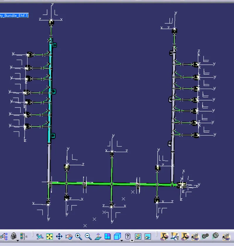
NOW we will asdd thisin drawing goto file>new>drawing>select A0>OK>FRONT View>go to flatten part select front view > adjust the parts as you want>click on screen see below image