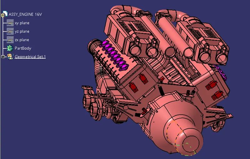
Project 1
AIM:
- To design and develop the Wire Harness Routing for the given V16 Engine by following the design and packaging rules.
OBJECTIVE:
- To define all the connectors electrically and save them in the Catalogue.
- Place all the connectors and cavities in the required position.
- Place P Clamps and Furrr Tree clips at the required position by following the packaging rules.
- To create the Wire Harness Routing as required and create branch points wherever required and also by following the packaging rules.
- To create the Wire Harness Flattening of the above routing.
- To display the flattened view in the drawing sheet.
ELECTRICALLY DEFINING CONNECTORS:
To Given Data:
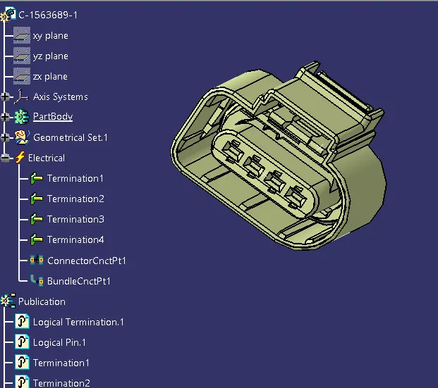
1. C-1563689-1
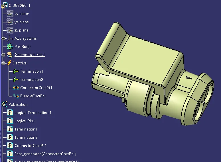
2. C-282080-1
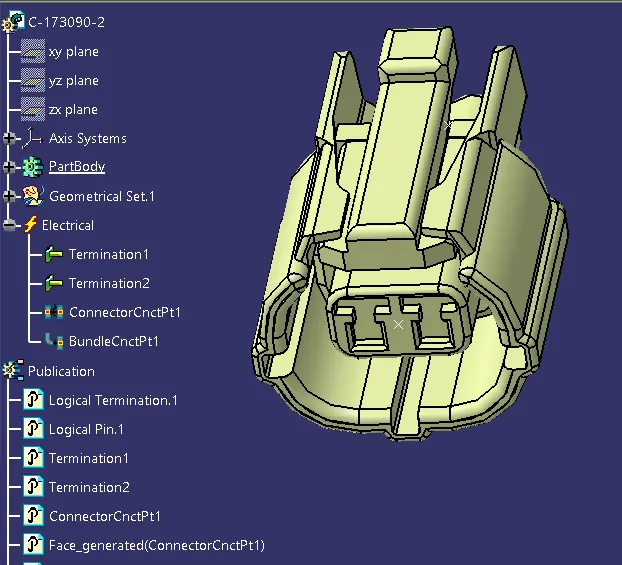
3. C-173090-2
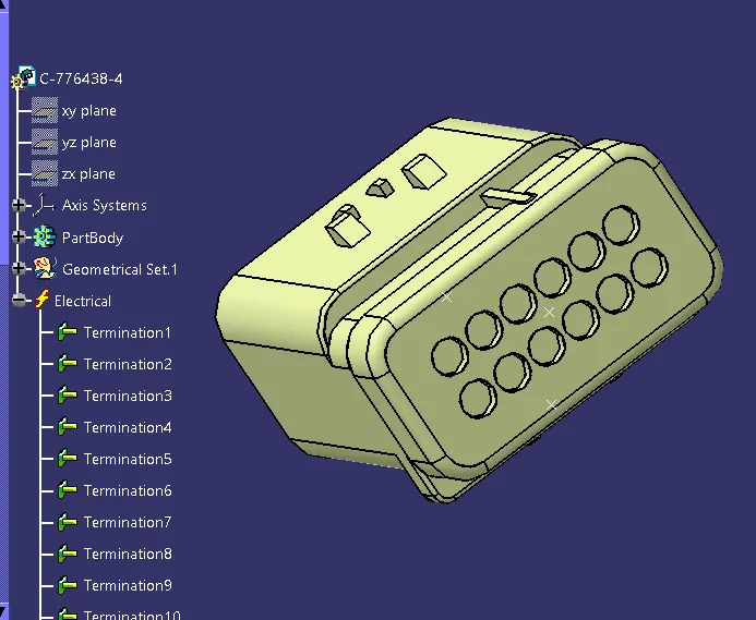
4. C-776438-4
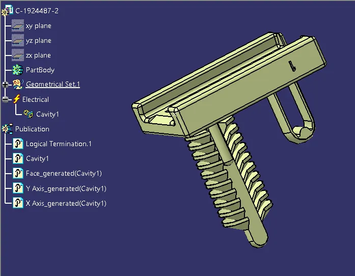
5. C-1924487-2
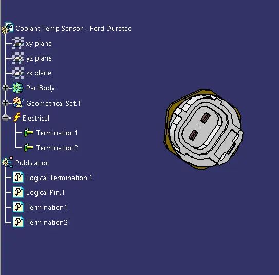
6. SPEED AND POSITION SENSOR:
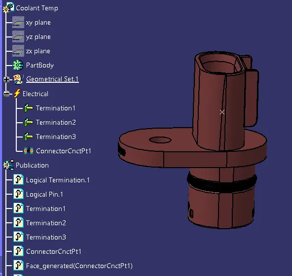
7. COOLANT/ENGINE OIL TEMPERATURE SENSOR:
8. P - CLAMP:
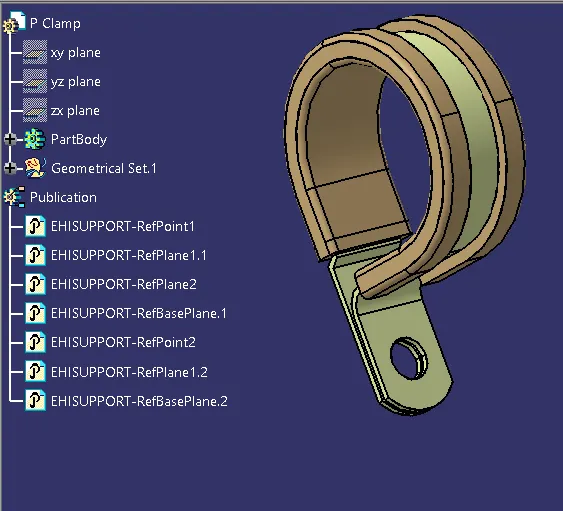
10. FURR TREE:
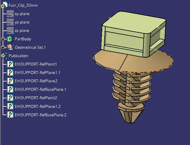
11. CHANNEL BOTTOM RIGHT SIDE:
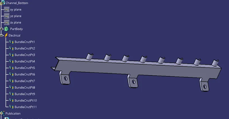
12. CHANNEL BOTTOM LEFT SIDE:
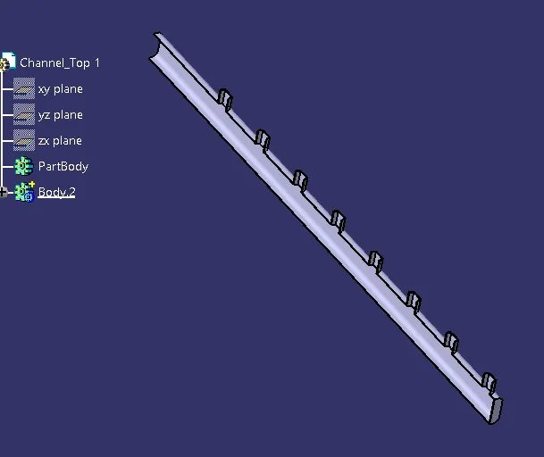
- Add all the connectors to the Geometric Bundle product file and place them using the 'Smart Move' or 'Manipulation Tool' command and the compass into their desired location.
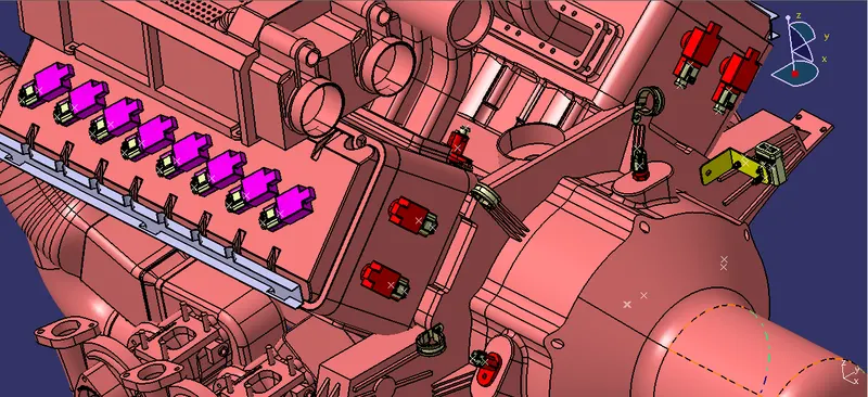
HARNESS ROUTING
Wire Routing
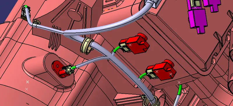
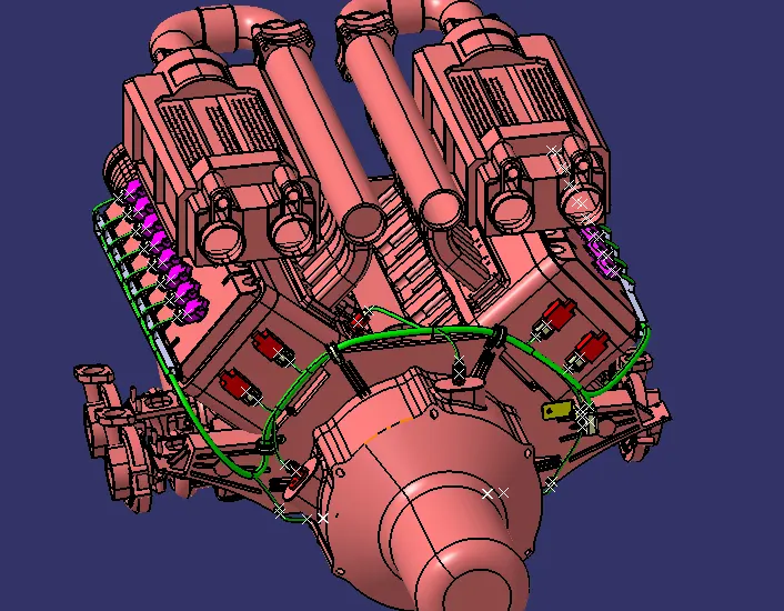
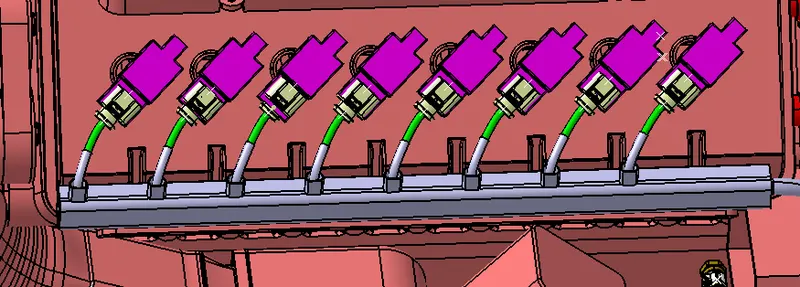
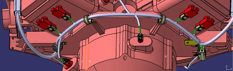
Final Routing
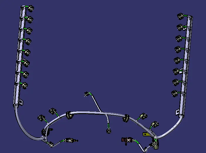
Wiring Harness Flattening
After checking all the bundle segments are linked we need to do the flattening
Switch to the flattening workbench
Select the Harness flattening parameter from the Catia workbench
Select All Tabs and use the setting for our requirement
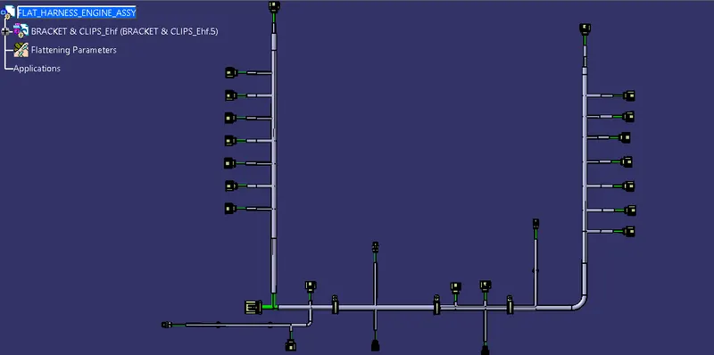
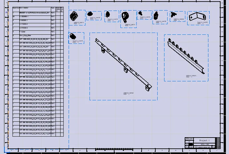
- After the wire bundle is flattened in the respective product file and workbench it can be represented in the drawing sheet.
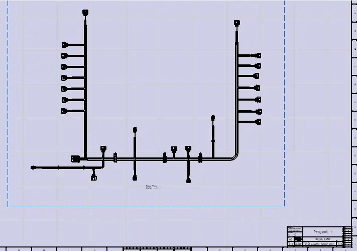
- The Bill of Material, different connectors used, and different clips and clamps used can be added to the drawing sheet for further reference.
REPRESENTATION OF THE FLATTENED WIRE IN THE DRAWING SHEET:
Conclusion:
In this way, we have routed the wiring harness for the V16 Engine. Also, prepared a flattened view drawing with the proper sheet in CATIA V5